HAL Id: cea-02339255
https://hal-cea.archives-ouvertes.fr/cea-02339255
Submitted on 14 Dec 2019HAL is a multi-disciplinary open access archive for the deposit and dissemination of sci-entific research documents, whether they are pub-lished or not. The documents may come from teaching and research institutions in France or abroad, or from public or private research centers.
L’archive ouverte pluridisciplinaire HAL, est destinée au dépôt et à la diffusion de documents scientifiques de niveau recherche, publiés ou non, émanant des établissements d’enseignement et de recherche français ou étrangers, des laboratoires publics ou privés.
C. Girold, S. Francois, L. Petit, S. Catherin, T. Prevost, E. Fourcy, G.
Lecomte, A. Viand
To cite this version:
C. Girold, S. Francois, L. Petit, S. Catherin, T. Prevost, et al.. French Innovative Processes in the Field of Thermal TreatmentFor Decommissioning and Legacy Waste. Waste Management 2018, Mar 2018, Phoenix, United States. �cea-02339255�
French Innovative Processes in the Field of Thermal Treatment For Decommissioning and Legacy Waste - 18085
Christophe GIROLD1, Sébastien FRANCOIS1, Laurence PETIT2,
Stéphane CATHERIN2, Thierry PREVOST3, Etienne FOURCY3,
Guillaume LECOMTE4, Alain VIAND5
1 Commissariat à l’Énergie Atomique (CEA), Nuclear Energy Division
Enrichment, Decommissioning and Waste Research Department CEA, DEN/DE2D, BP 17171 - 30207 Bagnols-sur-Cèze Cedex, France
2 National Radioactive Waste Management Agency (ANDRA)
Research and Development Division, Waste Packages and Material Department 1-7, rue Jean-Monnet - 92298 Chatenay-Malabry Cedex – France
3 AREVA NC, Dismantling and Waste Management Division
Tour AREVA 1 place Jean Millier – 94084 Paris la Défence Cedex – France
4 ECM TECHNOLOGIES
46 rue Jean Vaujany – 38100 Grenoble - France
5 A3I
255 rue Gustave Eiffel – 26290 DONZERE - France ABSTRACT
In order to optimize decommissioning waste management and better anticipate related issues, French nuclear waste producers CEA and AREVA, and the French Agency in charge of radioactive waste disposal (ANDRA) have decided to collectively develop technologies mastering costs, schedules and dose uptake as well as optimizing waste volumes and repository safety. In this context, several innovative projects have emerged over the past few years to develop specific thermal treatment processes. This paper focus on four new processes, presenting their goals, technical descriptions and first experimental results.
INTRODUCTION
The decommissioning of nuclear facilities and legacy waste treatment represent a global industrial challenge. In France, decommissioning activities will generate large volumes of radioactive waste, mainly low activities with a fairly homogeneous typology (metallic components, rubble), for which disposal routes already exist. However, some types of waste, due to their radiological and/or physical-chemical characteristics, cannot be easily conditioned and disposed of and, in a few cases, has no disposal route. Such waste may arise from former activities for which requirements for conditioning and disposal have evolved. This is particularly true for legacy waste.
In order to optimize decommissioning waste management and better anticipate related issues, French nuclear waste producers CEA and AREVA, and the French Agency in charge of radioactive waste disposal (ANDRA) have decided to collectively develop technologies mastering costs, schedules and dose uptake as well as optimizing waste volumes and repository safety. In this context, several innovative projects have emerged over the past few years to develop specific thermal treatment processes.
The paper focus on four new processes, presenting their goals, technical descriptions and first experimental results:
The IN CAN MELTER process, developed in the frame of the “DEM & MELT” project, a small and inexpensive in can vitrification tool, specifically designed to be used directly on site for high level inorganic solid or liquid waste such as tank deposits, zeolites, sludge…
The PIVIC Process, a plasma and induction coupled incineration / vitrification process to treat mixed organic and metals stream highly contaminated with plutonium (ILW),
The IDOHL process, a small induction plasma treatment process for organic liquid waste,
The ELIPSE process, a very innovative organic liquid treatment process (solvents, TBP…), implementing a submerged non transferred oxygen arc plasma.
THE “DEM & MELT” PROJECT Scopes and objectives
Some waste streams from dismantling operations are identified as an issue in terms of handling, transportation, adapted conditioning matrix for disposal within the existing regulations. This is for example the case of high active deposits remaining in the equipments of shut down facilities. The numerous constraints associated with the management of such waste leads to investigate the implementation of an in situ conditioning treatment able to produce a waste package complying with existing disposal routes and/or on-site storage facilities.
As grouting or cement matrixes are prone to hydrogen production or anyway would lead to a huge increase in volume, they seem excluded. In this context, only a glass matrix seems able to bring a satisfying answer as the glass material and the vitrification processes have demonstrated to be adapted to high level waste and can be flexible enough to accommodate a variable waste stream.
In this frame, the “DEM & MELT” (D&M) project is a project of Industrial Research, between CEA, AREVA, ECM Technologies and ANDRA. It has the ambition to bring a new solution by developing a specific vitrification tool to be implemented in situ and specifically designed to match the requirements and constraints of a Decommissioning and Dismantling (D&D) project. The amounts of identified high
level waste from dismantling operation to be treated are low, generally around a few hundred kilos for a given spot but scattered in different locations. This is significantly a different case than known industrial vitrification processes and shops which are devoted to treat, in a single place, large stream for a long period of time. The challenge is then to develop a process and a technology, flexible enough to match various waste streams and making it cost effective to have one tool per spot, designed from the start and to be dismantled after use (disposable vitrification tool). The rate of treatment could therefore be compatible with a small size installation with limited capacity. The challenge is then to develop a compact vitrification technology:
For high or medium level waste,
Flexible enough to accommodate uncertainties on waste composition and however producing a describable package with source term calculation methodology for long term storage,
Adequately dimensioned and compact to be installed and operate inside a decommissioned cell,
Designed for a short duration of use as a decommissioning tool aimed to be dismantled just after the treatment operation,
Producing a small amount of secondary waste,
At low investment and operation cost.
To achieve the objective of delivering a Technology Readiness Level (TRL) 6 process and provide all the basic data necessary to start an industrial application at the end of the project (2020), the project took as a basis a previous development which is nearly completed, the IN CAN MELTER technology (see next paragraph). The D&M project started in 2016 and is sequenced in 2 periods:
A first phase to study the feasibility, 2016-2018. During this phase, a reference D&D waste has been chosen and a preliminary assessment of glass matrix is performed as well as the definition of the fundamentals of the process (functional analysis, engineering studies for industrial layout and nuclearization feasibility). First tests using and existing IN CAN MELTER pilot scale equipment are realized and a first approach of process flowsheet is done to provide sizing figures, TRL 5. A pilot scale prototype will also be designed during this period.
A second phase of development and tests, 2018-2020. This phase will be used to design build the pilot scale prototype, refine glass design and define glass sustainability studies with regards to the development of package description methodology in the face of waste variability. This phase will provide a preliminary book of final process and a preliminary package description, TRL 6.
DEM&MELT Process description
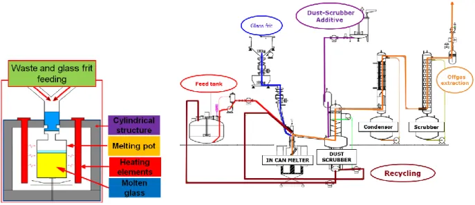
The D&M project takes as a basis a previous development made by CEA for its own needs, the IN CAN MELTER technology for defense waste (Figure 1) [1, 2]. In this
process, the container is used as a crucible ("IN CAN") that is renewed with each batch:
As the crucible is renewed for each batch, that greatly simplifies the equipment and makes it very robust,
There is indeed no need to drain the glass,
Corrosion problems are limited by the batch limited time,
The secondary wastes are limited to the heater as there do not remain after use any components that have been in contact with the molten glass,
Thanks to its small size, the crucible can be easily heated by a simple and robust resistance heated furnace, inexpensive, easy to maintain, easy to implement. This heating mean allows to have a metallic fraction in the canister,
The process has shown considerable flexibility as it will for example for the CEA application be exploited only with two shift teams, idling without operators during night shifts,
The compactness and basic technology of the IN CAN MELTER makes it a low investment equipment compare to other technologies.
The gases treatment is composed of a compact liquid gases treatment adapted from the proven High Level Waste vitrification process used in La Hague facility: a dust scrubber whose retention is continuously recycled with the main feed, a condenser and a gas scrubber.
Fig. 1. The IN CAN MELTER: melter and whole process. DEM&MELT State of the R&D 2017
Prototype development
A new prototype has been designed and is under construction for a startup at the beginning of 2019. This prototype will use a 110 liters canister (approximatively
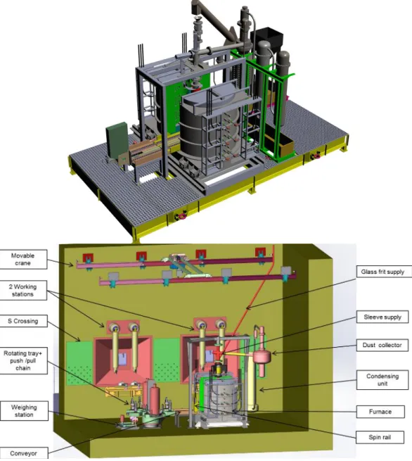
300 kg of glass) which can be inserted after the vitrification operation in a standard qualified canister (French “CSD” canister) as over pack (canister already used in nuclear industry in several countries for compacted waste conditioning). The furnace will have three separate heating zones from bottom to top to manage thermal treatment in the canister. The melter can be fed either with liquid waste or with solid waste. As it can be seen on Figure 2, the studies have focused on the optimization of the footprint, all the major equipments of the process being embedded on a single frame (melter, feeders, and first stage of gases treatment). During these detailed studies, all the nuclearization aspects have been taken into account, such as the choice of the materials, the maintenance operations, to provide a process that can be operated in a hot cell if required by the activity of the waste to treat.
Fig. 2. D&M prototype under construction (top), D&M feasibility studies for hot cell operation.
Preliminary tests
Using the existing IN CAN MELTER prototype, preliminary tests have been performed before starting the building of the new DEM&MELT prototype. The objective was to test the vitrification of an identified waste from dismantling operation in Marcoule (Nuclear Site in Chusclan – France) [3] both in liquid and solid feeding. The waste range composition is given in table I, it represents deposits that are found in old tanks or evaporators from Marcoule shutdown reprocessing facility (named UP1). Cs_137 represent more than 95% of the activity of these deposits. The main elements (about 50% in weight) composing the deposits are Zr, Si, Mo, Fe and P. Phosphorus exists as phosphate, which is the end-product of the solvent degradation. Comprehensive reviews of these results, of the reprocessing literature and of the operating history lead us to conclude that the deposits are mainly composed of 4 types of components:
Zr complexes : Zr(HPO4)2,nH2O and/or ZrMo2O7(OH)2
Cs complex of the type CsxPMoyOz
Pu complexes : Pu phosphate and/or Pu Molybdate,
Oxides and hydroxides: ZrO2,nH2O, PuO2,nH2O, MoO3,nH20.
Table I. Major constituents of the High Level deposits considered for a vitrification test [3] Element Elementary composition of the deposits (%w of dry
sample)
Tank 71.21A Tank 71.21B Tank71.21C
Zr 14 – 17 10 – 18 16 – 21 P 7 – 11 4 – 11 5 - 36 Si 3 - 10 4 – 23 3 - 33 Mo 3 - 7 0.4 – 8 3 - 30 Fe 0.5 - 3 1 – 2 1 - 4 Al 0.5 – 1.4 0.5 – 1 0.5 - 2
Dose rate in contact with the deposit
(Gy/h) 245 150 38 Cs Specific activity of the deposits (Bq/g of dry sample) 2.109 _ 1.3 1010 2.109 _ 1.1 1010 4.4108 _ 1.1 1010
Surrogates of a mean composition of this waste have been prepared both in liquid and solid form with inactive cesium spiking. The liquid form simulating the waste recovered from the tanks with an aqueous retrieval process and the solid form simulating the same waste after a drying treatment for interim storage. A specific borosilicate glass has been calculated to incorporate 10% of waste loading.
For the liquid feeding test, 110kg of glass at 6kg/h of mean glass production have been produced at 1100°C from simultaneous feeding of the glass frit and the solution at 4 l/h (with an dry extract of 150g/l). For the solid treatment test, the IN CAN MELTER was preloaded with the glass frit and the dry waste. The thermal treatment consisted in rising progressively the temperature at 1100°C while marking temperature levels stops for the decomposition of the waste species and
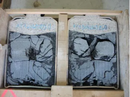
finally complete the canister with additional glass frit to obtain 110 kg of glass with a 10% waste loading. In both cases, the obtained glass was visually homogeneous (Figure 3). The cesium volatility has been measured during these tests. For the liquid feeding test the cesium volatility in the gases treatment is 0.6 % and for the solid test it is 0.2 %.
Fig. 3. Canister of the IN CAN MELTER cut in half after vitrification preliminary tests of a dismantling tank deposit high level waste.
THE “PIVIC” PROJECT Scopes and objectives
Transuranic Mixed metallic and organic wastes are produced during the MOX (Mixed Oxides) fuel manufacturing cycle, where MOX powders and pellets are handled in gloveboxes. Their characteristics are to contain a mixture of organic elements, metal and mineral materials contaminated with uranium, plutonium and americium (ILW). Those waste are source-separated and collected in a selective way according to different “families”:
Organic wastes: gloves from glove boxes, wipes, windows of glove boxes, plastics (PVC…),
Metallic wastes and various elements: electric equipment, defective mechanical products, tooling,
Filters: first filtration barrier, second filtration barrier, grinding machine pre-filters, labs filters.
A new thermal process is under development to study a treatment scenario where the waste is stabilized by incineration / vitrification [4]. This new conditioning process has to meet various requirements:
Full destruction of organic matter,
Confinement of the radionuclides,
No pre-treatment or sorting,
The process will have to reduce the waste volume,
The final waste package must be compliant with the waste acceptance criteria for the French geological disposal facility CIGEO.
The expected benefits from this development is to provide a better safety in final disposal thanks to the organic mineralization, to stabilize the actinides in a solid matrix, to preserve disposal resources thanks to a volume reduction of around 7. PIVIC Process description
The purpose of the PIVIC process is to perform in a single reactor the incineration of the organic fraction of waste, the fusion of the metallic fraction, and the incorporation of the incineration residues in a glass matrix.
The waste are directly fed without preprocessing from the top of the introduction chamber. The gradual lowering of the load in the combustion chamber allow the control of the incineration velocity of the waste.
The water jacket combustion chamber, receives an oxygen non transferred plasma torch to perform the organics incineration.
The fusion module is using an in can melting technology, heated by direct low frequency induction. The power is deposited in the metallic phase from the waste found in the bottom of the crucible. This crucible is used as part of the process for the duration of its filling, and as primary container, a new container is placed after each filling.
Fig. 4. PIVIC process description.
The gases exhausting from the heart of the process are treated in an afterburner chamber to complete the combustion if necessary (only for degraded mode since
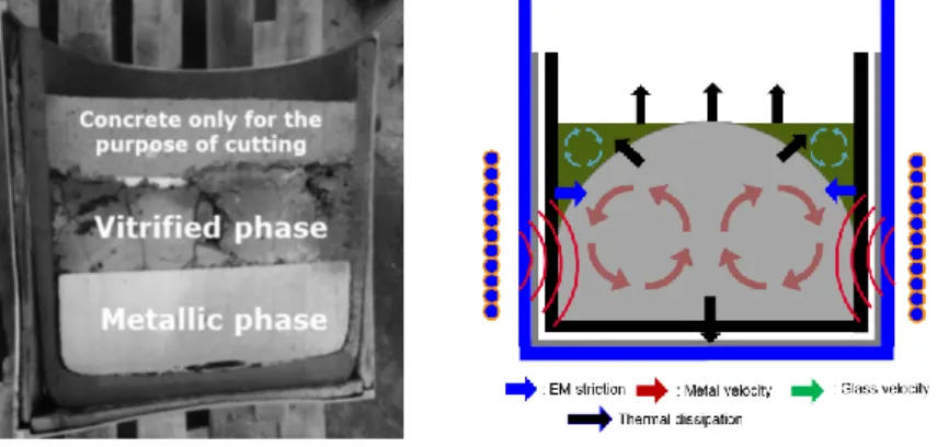
the oxygen plasma is likely sufficient to achieve a full combustion of the gases in the combustion chamber), a filtering step with an electrostatic precipitator and finally a gas scrubber to treat acidic gases (HCl) generated by the incineration. The process is not designed to perform the oxidation of metals present in waste and this is not a requirement. This leads to the production of a biphasic package with metal at the bottom and glass as a supernatant due to the difference in density (Figure 5).
PIVIC State of the R&D 2017
The R&D started in 2011, for the development and the qualification of the process and the package, a strategy of using inactive full scale prototypes has been chosen, technologically as close as possible to an industrial nuclearized release.
The first mockup was only the fusion module without the combustion chamber in order to study first the direct low frequency induction heating. This module was started in 2014 and has been operated for two years. During 2017, this first module has been upgraded to the full version of the PIVIC process as described in the previous paragraph. This full prototype is now starting.
Below are the significant achievements of the R&D program:
The low frequency induction melting concept of a biphasic material has been validated with the elaboration of thirty canisters of roughly 200 kg of metallic alloy made of stainless/copper/Aluminum (melting temperature ~ 1450 °C) and 50 kg of glass (melting temperature ~1250 °C). The canister is correctly cooled and the internal ceramic liner has sufficient corrosion resistance with respect to both the glass and metal phases.
The metallic fraction is strongly agitated by the electromagnetic forces (Figure 5). As an example, the surface velocity is around 0.1 m.s-1. The glass phase is also correctly agitated, being dragged by the molten metal, the surface velocity is around 0.01 m.s-1.
Fig. 5. PIVIC canister cut in 2 (left), thermal and hydrodynamic behavior of the direct induction heating process (right)
An aluminosilicate glass composition has been developed incorporating 15 % of ashes from the organic fraction of the waste. During glass production, the ashes incorporation is fast due to the strong electromagnetic stirring.
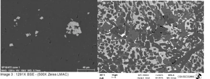
The package has good macroscopic separation of glass and metal phases (figure 5). In the absence of aluminum in the metals, the glass is homogeneous with a low enrichment of oxidized steel elements (Cr, Mn and Fe) which can crystallize at high concentrations. High concentrations of aluminum in the metals lead to a more crystalline oxide phase since the aluminum is fully oxidized by the glass phase (Figure 6)
Fig. 6. PIVIC glass product, without aluminum on the left And with high concentration of Al in the waste on the right.
The simulants of the actinides are exclusively found in oxides form, dissolved in the glass or in the form of silicates in the case of high concentrations of aluminum.
Thanks to an oxygen plasma mockup, the feasibility to manage the combustion of the organics by the selected feeding mode (gradual lowering of the load to the bottom of the reactor) has been validated.
Early studies, based on thermal / hydrodynamic modeling and plasma benchscale with surrogates has shown that the plutonium retention rate will be low enough to be compatible with industrial exploitation, in term of criticality management.
THE “MILOR” PROJECT Scopes and objectives
The MILOR project, started in September 2017 for four years, is a tripartite project of Industrial Research, between CEA, ANDRA and A3i, which aims the development up to pilot scale of a process of mineralization of Radioactive Organic Liquid Waste (ROLW) by plasma. Two variants of complementary plasma technologies are evaluated: aerial plasma with the “IDOHL” process and submerged plasma with the “ELIPSE” process.
IDOHL Process description
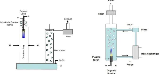
The principle of IDOHL is described in Figure 7 left. The plasma is generated by a 5kW generator and a high frequency inductor (> 1MHz) inducing in the plasma gas. The liquid to be treated is injected directly into the heart of the plasma by means of a suitable rod with the aim of the total destruction of the vaporized liquids in the plasma. The gases produced are then directed to a wet gas treatment system. IDOHL has been designed for organic liquids without mineral load and for treatment rates less than 0.5 l/h.
Fig. 7. “IDOHL” (left) and “ELIPSE” (right) process descriptions. IDOHL State of the R&D 2017
The studies started with a reference liquid waste surrogate: chloroform (CHCl3), an organic low level liquid waste with high amount of chloride and contaminated with tritium and carbon 14. The operating conditions are described in table II. The first results obtained through the treatment at 100g/h rate showed a good efficiency of destruction, but they highlight that the use of water as oxidative agent leads to limit the feeding rate because of two main issues: the high energy requirement to vaporize the water and the immiscibility of some organic liquids in water. These results led to propose the substitution of water by oxygen in order to increase sensibly the throughput of liquid supposed to be incinerated in the plasma [5].
Wet scruber NaOH Filter Exhaust Air Air Inductively Coupled Plasma Organic Liquid Ar O2
Table III. IDOHL Operating conditions
Parameters Values
Supplied plasma power 4 – 4.2 kW Pressure 1 × 10⁵ Pa
Total argon flow 40 NL·min-1
Oxygen flow 7 – 28 NL·min-1
Chloroform 100 – 400 g·h-1
O2/CHCl3 molar ratio 15–30
Additional air flow 60 NL·min-1
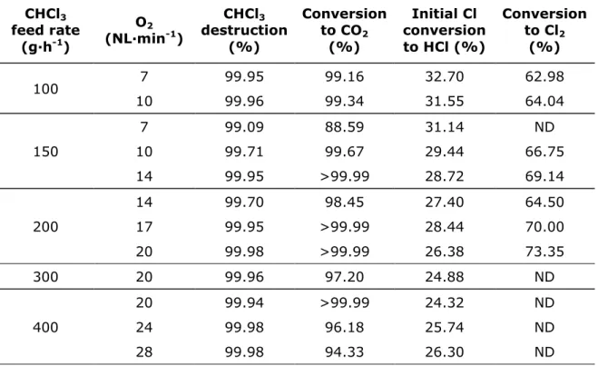
Table III. Conversion of CHCl3 in IDOHL
CHCl3 feed rate (g·h-1) O2 (NL·min-1) CHCl3 destruction (%) Conversion to CO2 (%) Initial Cl conversion to HCl (%) Conversion to Cl2 (%) 100 7 99.95 99.16 32.70 62.98 10 99.96 99.34 31.55 64.04 150 7 99.09 88.59 31.14 ND 10 99.71 99.67 29.44 66.75 14 99.95 >99.99 28.72 69.14 200 14 99.70 98.45 27.40 64.50 17 99.95 >99.99 28.44 70.00 20 99.98 >99.99 26.38 73.35 300 20 99.96 97.20 24.88 ND 400 20 99.94 >99.99 24.32 ND 24 99.98 96.18 25.74 ND 28 99.98 94.33 26.30 ND ND: Not Determined
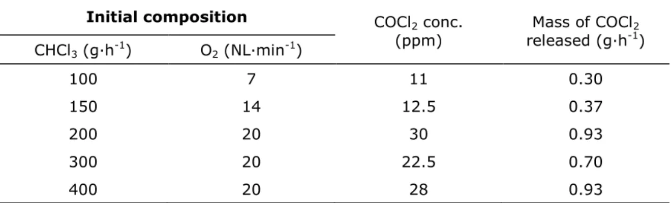
The experiments performed with this new running mode have been carried out with CHCl3 for feeding rates ranging from 100 to 400g/h. As forecast through a thermodynamic approach, the results display a destruction efficiency upper than 99% (Table III) and assure that the production of phosgene COCl2 remain small even if the hydrogen coming from water previously has been eliminated (Table IV). Indeed, less than 1g/h of phosgene is produced when HCl and Cl2 content remain within the regulation limits in exhaust gas. This shows that the temperatures inside the plasma area are high enough to transform molecules into atoms and also that
the oxygen content is sufficient during the cooling step to obtain finally oxidized stable and non-toxic molecules such as H2O and CO2.
Table IVV. Maximum phosgene release per chloroform injected in IDOHL Initial composition COCl2 conc.
(ppm) released (g·hMass of COCl-12)
CHCl3 (g·h-1) O2 (NL·min-1) 100 7 11 0.30 150 14 12.5 0.37 200 20 30 0.93 300 20 22.5 0.70 400 20 28 0.93
Based on these results, the IDOHL process can know be installed in a radioactive environment to validate the destruction of contaminated wastes. Some design modifications are on the way to accept ROLW containing a small amount of mineral (around 1%w). The gas cleaning system is also being modified in order to be able to use wet or dry way depending on the needs (a dry treatment would allow to produce a solid residue directly compatible with grouting).
ELIPSE Process description
A schematic diagram of the ELIPSE process is shown in Figure 7 right. A plasma torch is submerged in an aqueous solution of demineralized water flowing in a semi-closed loop. During the combustion of the organic charge of the waste introduced in the plasma plume, this solution is progressively loaded with the mineral part of the waste and also heat up under the effect of the thermal radiation of the plasma torch and the calorific value provided by the combustion of the waste. The aqueous solution is thus continuously cooled using a heat exchanger and if necessary, neutralized by controlled addition of NaOH for pH stabilization. The mineral fraction of the waste is recovered by continuously filtering the solution.
The organic liquid waste is injected into the heart of the oxygen plasma via a nozzle placed at the end of the plasma torch. This plasma nozzle is the only hot point of the process, all the rest is maintained at the temperature of the aqueous solution which provides a triple role for the combustion gases: quenching, cooling and gas washing. The combustion gases produced, mainly CO2 and CO in a smaller quantity, are discharged into the gas extraction unit comprising a demister/condenser.
This original configuration (submerged plasma) allows the process to be compact while locally offering a high density of power. Thus, the process as a whole remains generally cold, which strongly limits the presence of corrosion phenomena in the other circuits of the process. It thus opens the way to the development of a versatile process for the treatment of a varied range of organic effluents chemically
different. ELIPSE has been designed to treat several liters per hour of mineral loaded ROLW.
ELIPSE State of the R&D 2017
Treatment tests were carried out for a phosphorus organic liquid, a mixture of TBP / dodecane, at a flow rate of between 1 and 5 L / h [6]. The efficiency of destruction of the organic effluent is established by Total Organic Carbon Content (TOC) measurement. Knowing the molarity and the initial amounts of carbon introduced into the process, it is possible to establish a destruction efficiency defined by the following relation (1):
(t) = (QCi(t)-QCs(t))/QCi(t) (1)
QCi(t) is the total introduced carbon at t, QCs(t) is the total measured carbon in the
solution at t.
Figure 8 shows the evolution of the residual organic carbon in the aqueous solution of the process circuit during a combustion test campaign at different injection rates of a TBP / dodecane mixture. Four different treatment rates were qualified in this example. Figure 8 also shows the evolution over time of the destruction efficiency
(t) established according to relation (1). The results obtained show that the residual organic carbon increases regularly over time with the feed rate, but without, however, degrading the destruction efficiency. The TOC concentration drop down in several minutes after stopping the feeding. This destruction efficiency is excellent since it remains at a value between 99.7 and 99.9% with a minimum value of 99.1% recorded at the very beginning of combustion. The calculation uncertainty associated with this destruction efficiency value was evaluated at 0.3%.
Figure 8: Change in TOC and performance of processing over time for different TBP/dodecan feeding rates
In order to further improve the performance of the ELIPSE process, further work has recently shown that the radiative properties of the plasma can be used to initiate Fenton-type photochemical reactions by means of the hydrogen peroxide produced in the aqueous solution of the process under the effect of plasma radiation [7].
CONCLUSION
The decommissioning of nuclear facilities and legacy waste treatment bring extremely variable waste in form, compositions and activity levels. Thermal treatments can provide interesting benefits such as volume reduction or chemical stabilization, helping waste producer to master costs, schedule, or to optimize final volume and repository safety. Various processes have to be developed to match the waste specificity with the reasonable balance of development. We have presented in this paper four specific chosen examples of processes currently being developed for particular needs: The DEM&MELT process for a small high level vitrification unit usable in a dismantling environment, the PIVIC process to stabilize mixed organics and metallic transuranic waste with high criticality risk management challenge, the IDOHL or ELIPSE processes for the destruction of the organic fraction of liquid waste.
REFERENCES
1. « Qualification of In-Can Melting Process Applied to Vitrification of High Activity Waste Solutions (HAWS) at the CEA’s Valduc Center: Description of Process and Equipment, Methodology and Initial Results”, P. Gruber, S. Lemonnier, J. Lacombe, A. Ledoux, Y. Papin, I. Hugon, J.L. Dussossoy, B. Batifol, L. Pescayre, WM 2010 Conference.
2. Development of In-Can Melting Process Applied to Vitrification of High Activity Waste Solutions (HAWS): Glass characterizations and process tests results”, P. Gruber, S. Lemonnier, J. Lacombe, Y. Papin, I. Hugon, B. Batifol, L. Pescayre, WM 2012 Conference.
3. “Management of HL deposits for the D&D of UP1 reprocessing plant. Retrieval and treatment scenarios including onsite simplified vitrification device”, E. Cantrel, A. Courtadon, S. Blanchard, C. Girold, WM 2015 Conference. 4. “Mixed Metallic and Organic Transuranic Waste Incineration / Vitrification”, C.
Girold, P. Charvin, I. Hugon, S. Ben Lagha, S. Catherin, WM 2016 conference.
5. Inductively coupled plasma torch efficiency at atmospheric pressure for organo-chlorine liquid waste removal: Chloroform destruction in oxidative conditions. G. Kamgang-Youbi, K. Poizot, F. Lemont. Journal of hazardous materials 244-245 (2013) 171-179
6. ELIPSE: An innovative technology for the treatment of radioactive organic liquids, F. Lemont, M. Marchand, M. Mabrouk, D. Milelli, JM. Baronnet, Nuclear technology, 198 :1, 53-63, DOI : 10.1080/00295450.2017.1289009 7. Thermo- and photo- oxidation reaction scheme in a treatment system using
submerged plasma, D. Milelli, F. Lemont, L. Ruffel, T. Barral, M. Marchand, Chemical engineering journal, 1385-8947/ 2017. Elsevier B.V. All rights reserved
ACKNOWLEDGEMENTS
The PIVIC, DEM & MELT and MILOR projects are partnership between CEA, industrial partners (AREVA, ECM Technologies, and A3I) and ANDRA. They are supported by the French government program “Programme d’Investissements d’Avenir” whose management has been entrusted to ANDRA.
![Table I. Major constituents of the High Level deposits considered for a vitrification test [3]](https://thumb-eu.123doks.com/thumbv2/123doknet/12987980.378954/7.918.103.770.527.836/table-major-constituents-high-level-deposits-considered-vitrification.webp)