HAL Id: cea-02863563
https://hal-cea.archives-ouvertes.fr/cea-02863563
Submitted on 10 Jun 2020
HAL is a multi-disciplinary open access
archive for the deposit and dissemination of
sci-entific research documents, whether they are
pub-lished or not. The documents may come from
teaching and research institutions in France or
abroad, or from public or private research centers.
L’archive ouverte pluridisciplinaire HAL, est
destinée au dépôt et à la diffusion de documents
scientifiques de niveau recherche, publiés ou non,
émanant des établissements d’enseignement et de
recherche français ou étrangers, des laboratoires
publics ou privés.
Controlling an Exoskeleton with EMG Signal to Assist
Load Carrying: A Personalized Calibration
Benjamin Treussart, Franck Geffard, Nicolas Vignais, Frédéric Marin
To cite this version:
Benjamin Treussart, Franck Geffard, Nicolas Vignais, Frédéric Marin. Controlling an Exoskeleton
with EMG Signal to Assist Load Carrying: A Personalized Calibration. MoRSE 2019 - International
Conference on Mechatronics, Robotics and Systems Engineering, Dec 2019, Bali, Indonesia.
pp.246-252, �10.1109/MoRSE48060.2019.8998701�. �cea-02863563�
2019 International Conference on Mechatronics, Robotics and Systems Engineering (MoRSE) 4-6 December 2019, Bali, Indonesia
Controlling an exoskeleton with EMG signal to
assist load carrying: a personalized calibration
1
stBenjamin Treussart
SRI, LASR CEA-List Saclay, France benjamin.treussart@cea.fr2
ndFranck Geffard
SRI, LASR CEA-List Saclay, France franck.geffard@cea.fr3
rdNicolas Vignais
CIAMSUniv. Paris-sud, Univ. Paris Saclay and Univ. d’ Orleans Orsay and Orleans, France
nicolas.vignais@u-psud.fr
4
thFrederic Marin
Biomecanique et Bioingenierie UMR CNRS 7338 Universite de Technologie de Compiegne
Compiegne, France frederic.marin@utc.fr
Abstract—Implementing an intuitive control law for an upper-limb exoskeleton to perform force augmentation is a challenging issue in the field of human-robot collaboration. The aim of this study is to design an innovative approach to calibrate electromyo-graphy (EMG) data in order to detect the intention to lift or put down a charge while wearing an upper-limb exoskeleton. Based on a low-cost EMG sensor bracelet placed around the arm (Myo armband, Thalmics Lab, Ontario), a subject-specific mapping procedure is implemented to discriminate motion intentions during lifting tasks with a 1-DoF upper-limb exoskeleton. The processing is divided into two main parts: (i) direction estimation with an artificial neural network, and (ii) a model-based intensity prediction. The mapping procedure has been tested on 7 healthy participants with a precision of 96.9 ± 3.1% for the classification and a RMS Error of 3.8 ± 0.8N at the end effector. This study opens up the way for fast-deployment applications involving exoskeletons or cobots.
Index Terms—EMG, Exoskeleton, Calibration, Intention De-tection
I. INTRODUCTION
Industrial workers are performing repetitive physical tasks, which expose them to musculoskeletal disorders (MSD) [1]. MSD is a major public health issue, with an impact on workers’ integrity and economics. Indeed, MSD are causing both loss in productivity and high healthcare costs. According to [2], MSD have led to the loss of 10 millions work days
in France in 2012, with an average cost of 21 ke per case
of MSD. A way to prevent MSDs could be to assist the workers during forceful exertions, e.g. load carrying tasks, thus relieving the strain they endure.
Exoskeletons could become a solution for industrial load carrying. Although, exoskeletons can be backdrivable (see sec. III-A), and they can help manipulating known and fixed
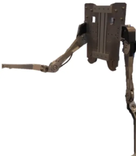
Fig. 1: Upper-limb exoskeleton
weights [3], the way they can handle various and unknown charges in a efficient manner is yet to be achieved. The knowledge of the user’s intention could help in this matter. Surface EMG signal processing demonstrated reliability in estimating the muscle force [4], and, consequently, it may be a relevant bio-signal to capture the motion intention.
Given a context of industry-oriented application, an al-gorithm based on a robust calibration process has to be implemented in order to design a subject-specific intuitive-to-use intention detection methodology to control an exoskeleton. This calibration process has to be reliable and not time-consuming to be operational.
II. PREVIOUSWORKS
EMG signals have already been used to control robotic devices [5], [6]. This biocybernetic approach uses EMG sig-nals into two different manners: discretely or continuously. The discrete-EMG method uses pattern recognition based on handcrafted features and a classifier trained with them [7] or some end-to-end neural networks [8]. The main inconvenience of this method of intention detection is its lack of flexibility. Indeed there is a trade-off between the panel of actions and the cognitive charge/reliabilty of the classification, which depends on the number of classes. In the case of a directionnal control, one class may correspond to one direction with a fixed speed [6].
On the other hand, a continuous-EMG method seems more adequate but it also presents disadvantages. First of all, it is more complex, due to the fact that the relations between the features of the EMG signals and the movement are highly non-linear [9]. In [10] a continuous 3D estimation of the position of the hand is performed with the use of 9 electrodes targeting specific muscles. Such precise requirements in the placement of the electrodes complicate the deployment and reinforce the user-dependent aspect of the method. In addition, these methods are more adapted to teleoperation, as well as prosthesis assistance rather than a situation where the torques of the robot and the user influence each other. In the current study, a mix of continuous and discrete approaches will be used to evaluate the intentions of the user. The current study is preliminary to torque control laws, and aims to relate user’s intentions to a torque. Torque values will be used rather than normalized EMG so that future implemented control laws will assure the same behavior for each user.
Finally, EMG data is individual-specific and that is why the signal processing requires to be calibrated. Different ways to calibrate EMG signal processing have been proposed. The calibration can be based on voluntary contraction to gather data for classification tasks. Usually, data from all the classes is recorded [11] but some works focus on recognizing one situation against several others, like with a 1-class classifier [12]. Another strategy is to use external load (i.e force sensors or set of weights) [4]. This approach is adapted for certain con-tinuous evaluation, but the use of force sensors increases the cost and the complexity of the procedure and the positionning of the sensors is usually critical. Others methods use external motion capture technology to calibrate with continuous data [13], however it does not enable to estimate the torque applied by the individual. In this study, an upper-limb exoskeleton will be used to collect data with reliable labels (class or torque value). This enables to control precisely the type of movement or effort made by the user.
To summarize, the discrete-to-continuous approach pre-sented in this study contributes from the point of view of practical implementation (using an exoskeleton both to label and as an excitation vector for identification). It is not only more flexible than a fully discrete method, but also it has much more potential of practical deployment than a fully continuous
r
shoulderd
shoulderL
armL
elbowL
forearmFig. 2: Representation of the DHM parameters [14] TABLE I: Table of the DHM parameters [14]
αi di ri θi Frame 1 0 0 rshoulder θ1 Frame 2 +π 2 dshoulder 0 θ2 Frame 3 0 Larm 0 θ3= 1.5 ∗ θ2 Frame 4 −π 2 Lelbow 0 θ4 Frame 5 0 Lf orearm 0 0
approach. Consequently, a low-cost surface EMG device will be used to foresee a practical use-case. More specific additions to the state of the art will be given in next sections of the current article.
III. SYSTEMSPECIFICATIONS
A. Exoskeleton
The exoskeleton used in this study is an under-actuated upper-body backdrivable type (Fig. 1). Each side consists of two segments (upper-arm and forearm) and four joints.
Two of the joints are passive (θ1 and θ4) and the other two
are proportionally linked and powered by the same actuator
(θ3 = 1.5 ∗ θ2 [15] (Fig. 2 and Tab. I) . The end effector
of the exoskeleton, that pulls the hand upward, is attached to the user’s palm of the hand by a strap. Backdrivability is ”the nature that when the force is added to the output axis, the output axis is moved by this force and this motion is conveyed to the input axis and the input axis is moved by this motion in the case of actuators or power transmitting mechanism” [16]. During the interaction, human and robotic forearm dynamics are coupled, which can be modeled as follows [17]:
(
MrΘ¨r+ brΘ˙r+ τFN L+ Qr(Θr) = τr− τi
MhΘ¨h+ JhtFe+ bhΘ˙h+ Qh(Θh) = τh+ τi
(1)
Where τi is the equivalent interaction torque between human
torque and M - the matrix of inertia, b - the viscosity, τFN L
- the non-linear friction and Q the gravity torque. Fe are the
external forces applied to the human and Jt
h - the jacobian of
the human. The subscripts r and h denote similar quantities related to robot and human systems, respectively. We are considering a quasi static interaction and we compensate the effect of gravity on the robot (Backdrivability ensures that
FN L is low [3]), which give us:
τh= −τ + JhtFe+ Qh(Θh) (2)
with :
τr= τ + Qr(Θr) + τFN L (3)
B. EMG Recording
The methodology of intention detection is expected to be functional, easy to deploy, low-cost, operational in real-time and be capable of securing homogeneity between individuals. Homogeneity in our case means that, despite the fact that the features of the EMG signals vary depending on the user, our methodology should output the same value of intensity for equal intentions of different users.
The Myo-Armband (Thalmic Labs, Ontario) meets the previous specifications. The armband was positioned around the arm to capture biceps and triceps muscle activities. The Armband is composed of eight pairs of dry electrodes. We optimized the longitudinal placement to maximize the EMG signal empirically. The raw output of the armband is a zero-mean signal coded over 8 bit, it has no unit and is comprised between -126 and +127.
C. Algorithm
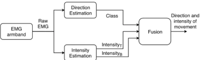
One could first consider using a calibration matrix as for the calibration of a 6-axis force-torque sensor. But, in this case, the non-linearity due to the model and due to EMG saturation leads to a complex and unstable parameter identification process. That is why a new algorithm is proposed here, more robust and simple, than the classical method. It is a mix of continuous and discrete methods. The discrete part enables to choose between continuous sub-parts similarly to [12]. The continuous sub-parts are simpler to calibrate than one using a fully continuous method. The continuous part brings flexibility and is designed to estimate the intention intensity. While the discrete part determines the intention direction. Moreover, this hybrid method also has the advantage of being directly exploitable for a control law. This methodology estimates the user’s intentions as a torque instead of a percentage of maximum contraction in order to have a user-independent output.
This process could be divided into two parallel blocks (Fig. 3): the first one is implemented to detect the direction of the action thanks to a classification designed in sec. IV. The second one is designed to estimate the intensity (see sec.V).
IV. DIRECTIONESTIMATION
A. Design
To detect the direction of the intention, an artificial neural network was designed for a four-class classification: rest,
EMG armband Direction Estimation Intensity Estimation Fusion Raw EMG Class IntensityT IntensityB Direction and intensity of movement
Fig. 3: General Approach (IntensityB and IntensityT
corre-spond respectively to the intensity of the Biceps activation and Triceps activation)
(a) Class Rest (b) Class Triceps
(c) Class Biceps (d) Class Co-contraction
Fig. 4: Description of the four different classes
elbow extension i.e. triceps activation, elbow flexion i.e. biceps activation, and co-contraction. The co-contraction class has been dissociated from the others and did not play a role in the discrimination of the direction of intended movement. These four classes represent the main actions at the elbow joint (1 DoF).
The present approach is using time windows that were fed to an artificial neural network similarly to [8]. Unlike with other classification approaches like [7], [18], there was no need to handcraft features. The final architecture of the network can be seen on Fig. 5. The general idea was inspired by architectures from computer vision like the VGG net [19]. The convolutions were used to extract features from a sample and then the fully connected layers act as a classifier. In computer vision 2D convolutions are used, but in this case, for a time varying signal it is more relevant to use 1D convolutions and parallelize the processing over the 8 channels. The fact that the convolutions were parallelized helped to both reduce the number of trainable parameters (around 3000) and gain in generalization.
A time window of 30 samples was used, or 150 ms given the sampling rate of the sensors, and it was decided not to use overlapping windows to create the database from 30-second recordings in order to reduce the risk of overfitting. Our database consisted of 800 samples for each participant. A drop-out layer was used to avoid over-fitting.
The Network was implemented with Keras (Python deep learning library), the Adam optimizer was used for training [20], and the loss chosen was the categorical cross-entropy
Conv 1D #1 size = 5 Conv 1D #2 size = 5 Conv 1D #3 size = 5 Flattening Layer Concatenation layer EMG electrodes Drop-out layer
Fully connected Layer with softmax (30,1)*8 (26,5)*8 (22,5)*8 (18,5)*8 (90,1)*8 (720,1) (720,1) (4,1) Shared Layers
Fig. 5: Architecture of the neural network
(eq. (6)). Rectified Linear Units (ReLU) (eq. (4)) were used as activation function between the layers except for the last one, which was a softmax activation (eq. (5)).
fReLU(x) = ( 0 if x < 0 x else (4) fsof tmax(xi) = exi PM c=1exc (5) floss(p) = − M X i=1
yo,i∗ log(po,i) (6)
• M is the number of class
• y is a binary indicator (0 or 1) if class label i is the correct
classification for observation o
• p is the predicted probability observation o is of class i
B. Training
To train the network designed in the previous section, 2 30-second-long data samples for each class were recorded. These recordings were used to create our training dataset and testing dataset (one recording per class for each).
The recording went as follows, twice, with rest between the steps :
• 30 seconds of biceps contraction at various intensities
(see sec. V-C)
• 30 seconds of triceps contraction at various intensities
(see sec. V-C)
• 30 seconds of rest
• 30 seconds of co-contraction at various intensities
The Table II displays the results for the 7 participants calculated with eq. (7). For each participant, only their own training data and testing data were used. An average precision
TABLE II: Precisions (eq. (7)) obtained on the testing sets
Person 1 2 3 4 5 6 7 Precision 0.999 0.969 0.992 0.928 0.999 0.924 0.974
of 96.9±3.1% was obtained. For this validation the placement of the electrode was the same as for the training.
P rec = 1 Nclasses ∗ Nclasses X i=1 ntrue positive,i
ntrue positive,i+ ntrue negative,i
(7) Where ntrue positive,iis the number of instances of the class i
correctly estimated, ntrue negative,iis the number of instances
estimated as the class i wrongfully and Nclassesis the number
of classes.
V. INTENSITY ESTIMATION
In this section a way to extract a notion of intensity of the intention from the raw EMG signals is proposed. The value obtained in the end was expressed in a force unit, and therefore was not user-dependent (do not depend on, for example, the skin conductivity of each participant).
A. Pre processing
First, the rectified signals were summed from all the sensors (eqs. (8) and (9)). The spatial information was lost but it was already exploited by the classification part. Also, this enabled to take advantage of the cross-talk effect which increased the measure range. Indeed, when the electrode placed right upon the muscle saturated, the ones next to it were still able to sense changes in the intensity of the muscle activation.
EM Grectif = abs(EM Gi) (8) EM Grectif,sum= 8 X i=1 EM Grectif,i (9)
Then the EM Grectif,sum signal is filtered through a
low-pass filter [21]. This filter is to be used in a real-time application, and, in the end, we want to use it for the command of a robotic device in a context of co-manipulation. So it has to have a low response time and little overshoot. Root mean square (RMS) and Mean filters are often used for smoothing an EMG signal [22], but there is a trade-off between response time and smoothing effect. When the size of the window is larger, the output is smoother but we introduce a greater lag. A Butterworth filter of order 2 and a 2 Hz cutoff frequency was chosen,and adapted to real-time with a sliding window approach, as it answered to our specifications.
B. Modeling
To ensure consistency among users, the model linking torque and low-pass filtered EMG presented in [23] will be used. And this would enable to design a user-independent control law despite using EMG signals.
τ = ua∗ e(c−b∗u) (10)
τ being the modeled torque, u the EMG signal and a,b and
c the parameters to be determined for the biceps and triceps
separately from calibration.
In the original article this model was calibrated in a con-trolled environment, there was one electrode placed precisely over the biceps and with the high sampling frequency (1 kHz) and the reference data was obtained by restraining the movements of the arm of the participants so that the load cell would record precisely the torque of the elbow. In this case, the use of this model is extended to two antagonist muscles, and with approximately-placed lower-sampling-rate electrodes. C. Mapping
The first stage of the mapping aimed to obtain the torque maxima and corresponding processed EMG for the activation of the Biceps (elbow flexion or lifting gesture) and Triceps (elbow extension or putting down gesture). For this part, the arm of the exoskeleton was controlled with a PD-position-control law, with a high proportional gain, in order to have a stiff behavior and be in a quasi-static state.
We proceeded as follow, with a rest between each step:
• 5 seconds of biceps maximum contraction
• 5 seconds of triceps maximum contraction
• 6 steps of 8 seconds going gradually from 0 to 80% of
biceps maximum contraction
• 6 steps of 8 seconds going gradually from 0 to 80% of
triceps maximum contraction
To get the biceps maxima the participant grabbed the end of the arm and forced against the robot arm upward (Fig. 4c) as hard as he/she can and held it for a 5-second acquisition. The same approach was used for the Triceps maxima, except that the participant put his/her fist on the end of arm and pushed down (Fig. 4b). With this first stage, the value of the maximum torque the participant was able to apply on the actuator was obtained. These values were used to design torque step protocol: the robot applied levels of torques from gravity compensation up to 80 % of the maximum and the user had to resist these torques. Each step lasted 8 seconds and was separated by a 1-second linear transition. This torque step protocol will ensure the precise levels of contraction are maintained by the participants.
Then, the first step for the Biceps part and the first two for the triceps part were removed from the data of the torque step protocol. Indeed these steps did not allow sufficient exertions from the participant (it was closer to a resting state). Data from the maxima of Biceps and Triceps were concatenated with their respective data from the torque step protocol. These concatenated data have been used as training data for the biceps activation and triceps activation classes (see sec. IV-B). Finally, the parameters were estimated with a Levenberg-Marquardt non-linear regression [24]. For clarity, the results are presented for only one participant in Fig. 6. Two sets of three parameters were obtained, to characterize the activity of
Fig. 6: Result of the regression for one participant for the mapping of the extension movement
0 100 200 300 400 500 600 0 0.1 0.2 0.3 0.4 0.5
Low-pass Filtered EMG
Torque
Modeled torque from Low-passed EMG and the parameters of each person
Processed EMG (no unit)
Torque (
N.m)
Fig. 7: Modeled torque with eq. (10) depending on EMG values, with the parameters of each participant
the biceps and the triceps. During the operating phase, the set of parameters to be used will depend on the classification phase, i.e. if it is an upward or downward movement intention. On Fig. 6, 7, 8a and 8b the torque is expressed at the actuator. On Fig. 7 the torque obtained using the parameters from the mapping and eq. (10) was plotted. The model was plotted up to the maximum processed EMG recorded for each participant (see sec. VI). First of all, EMG characteristics appeared quite heterogeneous between participants, which highlighted the need of a user-specific mapping. Secondly, for one of the participant, the graph is drastically decreasing at one point. This may be due to co-contraction phenomenon during the recording. A way to avoid that would be to check the level of co-contraction and asked the participant to redo the sample if it is above a certain threshold.
VI. EXPERIMENTALTESTING
Seven participants were asked to contribute to the experi-ment. There were six men and one woman, all of them aged from 20 to 35 and in good health. After calibration (sec. IV and V), to test the present procedure, the following setup was proposed. During one minute, each participant performed varying torques in the 2 directions available. The exoskeleton was resisting them, like for the maxima recordings (see sec.
V-C). The fusion of the classification and intensity evaluation was realized as follow : the classes Biceps and Triceps were used to sign the intensity, positive and negative respectively. If a rest class is detected we assign the intensity the value 0. At the moment, the co-contraction class was handled in the the maner as the rest class
On the Fig. 8a raw data obtained from one participant are presented. The class is obtained by taking the most likely output of the classifier, without threshold on the confidence score. It can be observed that the class (in green) presents important variations at the transitions. It can be explained by how the dataset was designed. Indeed, the whole spectrum of possibilities for each class were represented and at low intensities the differences became very subtle. For example, a low intensity co-contraction sample would have a signal very similar to a low intensity biceps contraction only or even a rest state. A way to stabilize the classification could be to consider one of the classes as the default state, rest in the present study, and put a threshold on the confidence score for the other to be accepted.
The processed results of 1 participant in Fig. 8b are pre-sented. The estimated torque was used for the value and the class information to get the sign, i.e. positive for biceps class and negative for triceps, 0 otherwise, to calculate the estimated torque. An error of classification between the classes could lead to important mismatch and discontinuities of the estimation. Subsequently, the role of the classifier is crucial. One disadvantage associated to the classifier is the capacity to consider low intensity movements, e.g. areas where the clas-sifier was hesitant on Fig. 8a resulted in small discontinuities on Fig. 8b.
In Table III, RMS errors were calculated. They were ex-pressed in Newton at the end-effector. Indeed, in this study the actuator’s torque was used as the reference but results were converted for comparison purposes. We can see that, during the test experiment, an error of 3.8 ± 0.8N on average was obtained, which is acceptable for applications focused on force augmentation for heavy load carrying. If we compare the results with [25], by converting their results as a force in the palm, they obtained on average 2.0 ± 0.2N . The current error is twice as important but the use a load cell was bypassed and it did not require a precise set up of EMG electrodes. TABLE III: Errors obtained during the validation experiment
Person 1 2 3 4 5 6 7
RMS τmotor(N.m) 0.0371 0.0621 0.0415 0.0387 0.0619 0.0478 0.0433
RMS Fendef f ector(N) 2.953 4.943 3.303 3.080 4.927 3.804 3.446
VII. CONCLUSIONS AND FUTURE WORK
In this article, an algorithm of intention detection oriented on the assistance for load carrying was presented. A new cal-ibration method was proposed using a backdrivable exoskele-ton that is time-efficient and practical. This research opens perspectives in industrial use cases. The current experiment
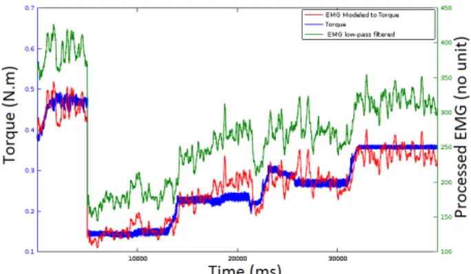
(a) Raw results, in blue the torque of the actuator, in red and cyan the torque estimated from EMG (if the biceps is activated or if it is the triceps), and in green the most likely class (0 = rest, 1 = triceps, 2 = biceps, 3 = co-contraction)
(b) Processed results, in blue the torque of the actuator, in red the estimated torque from the EMG signal
Fig. 8: Results of the test for one of the 7 participants
showed that our methodology enabled to estimate the torque produced by a user.
The future of this project lays in exploring the possibility of a unified classifier which would help avoid manual subject-specific adjustment, i.e. a network trained on several partic-ipants which would be able to process data of new users. This would improve the time efficiency aspect of the proposed method. In addition, the robustness to the re-positioning of the armband between two sessions has to be formally evaluated. Moreover, the precision of our results could be improved by increasing the acquisition rate of EMG electrodes.
The calibration procedure presented in the current study has been performed in static conditions. As the load carry-ing assistance will be provided by the exoskeleton durcarry-ing dynamical tasks, it is expected that the control law will be efficient for dynamic tasks with low velocity [26]. However, with high dynamics tasks stability issues will probably need to be addressed by the control law. Other researches will consist in implementing controllers based on the output of this module of intention detection, and experimenting on the effect of the assistance of our exoskeleton in carrying various loads at various speeds. Despite the heterogeneous aspect of EMG signals, the proposed calibration method will ensure the reproduction of the same behavior of the controllers with different users.
REFERENCES
[1] N. Vignais, M. Miezal, G. Bleser, K. Mura, D. Gorecky, and F. Marin, “Innovative system for real-time ergonomic feedback in industrial man-ufacturing,” Applied ergonomics, 2013.
[2] INRS. (2015) Troubles musculo-squelettiques -
statis-tiques. [Online]. Available:
http://www.inrs.fr/risques/tms-troubles-musculosquelettiques/statistiques.html
[3] P. Garrec, “Design of an anthropomorphic upper limb exoskeleton actuated by ball-screws and cables,” Bulletin of the Academy of Sciences of the Ussr-Physical Series, vol. 72, no. 2, p. 23, 2010.
[4] M. Al Harrach, V. Carriou, S. Boudaoud, J. Laforet, and F. Marin, “Analysis of the semg/force relationship using hd-semg technique and data fusion: A simulation study,” Computers in biology and medicine, vol. 83, pp. 34–47, 2017.
[5] A. Ajoudani, A. M. Zanchettin, S. Ivaldi, A. Albu-Sch¨affer, K. Kosuge, and O. Khatib, “Progress and prospects of the human–robot collabora-tion,” Autonomous Robots, pp. 1–19, 2018.
[6] C. DaSalla, J. Kim, and Y. Koike, “Robot control using electromyog-raphy (emg) signals of the wrist,” Applied Bionics and Biomechanics, vol. 2, no. 2, pp. 97–102, 2005.
[7] P. Phukpattaranont, S. Thongpanja, K. Anam, A. Al-Jumaily, and C. Limsakul, “Evaluation of feature extraction techniques and classifiers for finger movement recognition using surface electromyography signal,” Medical & biological engineering & computing, pp. 1–13, 2018. [8] M. Gandolla, S. Ferrante, G. Ferrigno, D. Baldassini, F. Molteni,
E. Guanziroli, M. Cotti Cottini, C. Seneci, and A. Pedrocchi, “Artificial neural network emg classifier for functional hand grasp movements prediction,” Journal of International Medical Research, vol. 45, no. 6, pp. 1831–1847, 2017.
[9] F. E. Zajac, “Muscle and tendon properties models scaling and ap-plication to biomechanics and motor,” Critical reviews in biomedical engineering, vol. 17, no. 4, pp. 359–411, 1989.
[10] P. K. Artemiadis and K. J. Kyriakopoulos, “An emg-based robot control scheme robust to time-varying emg signal features,” IEEE Transactions on Information Technology in Biomedicine, vol. 14, no. 3, pp. 582–588, 2010.
[11] K. K. Jung, J. W. Kim, H. K. Lee, S. B. Chung, and K. H. Eom, “Emg pattern classification using spectral estimation and neural network,” in
SICE, 2007 Annual Conference. IEEE, 2007, pp. 1108–1111.
[12] S. Amsuess, I. Vujaklija, P. Goebel, A. D. Roche, B. Graimann, O. C. Aszmann, and D. Farina, “Context-dependent upper limb prosthesis control for natural and robust use,” IEEE Transactions on Neural Systems and Rehabilitation Engineering, vol. 24, no. 7, pp. 744–753, 2015. [13] L. Imrani, S. Boudaoud, K. Kyiyoka, J. L. K Lepeti and, and F. Marin,
“Evaluation of motor abilities with aging using hd-semg and imu data,” 14th International Congress of the European Union Geriatric Medicine Society, Berlin, Germany.
[14] W. Khalil and J. Kleinfinger, “A new geometric notation for open and closed-loop robots,” in Proceedings. 1986 IEEE International Confer-ence on Robotics and Automation, vol. 3. IEEE, 1986, pp. 1174–1179. [15] P. Garrec, Y. Perrot, D. Ponsort, and A. Riglet, “Patent: Exoskeleton
arm having an actuator,” 2012, uS9375325B2.
[16] T. Ishida and A. Takanishi, “A robot actuator development with high backdrivability,” in Robotics, Automation and Mechatronics, 2006 IEEE
Conference on. IEEE, 2006, pp. 1–6.
[17] S. Bastide, N. Vignais, F. Geffard, and B. Berret, “Interacting with a “transparent” upper-limb exoskeleton: A human motor control ap-proach,” in 2018 IEEE/RSJ International Conference on Intelligent
Robots and Systems (IROS). IEEE, 2018, pp. 4661–4666.
[18] L. Cerina, G. Franco, P. Cancian, and M. D. Santambrogio, “Robustness of surface emg classifiers with fixed-point decomposition on reconfig-urable architecture,” in 2018 IEEE International Parallel and Distributed
Processing Symposium Workshops (IPDPSW). IEEE, 2018, pp. 146–
153.
[19] K. Simonyan and A. Zisserman, “Very deep convolutional networks for large-scale image recognition,” arXiv preprint arXiv:1409.1556, 2014. [20] D. P. Kingma and J. Ba, “Adam: A method for stochastic optimization,”
arXiv preprint arXiv:1412.6980, 2014.
[21] N. Hogan, “A review of the methods of processing emg for use as a proportional control signal.” Biomedical engineering, vol. 11, no. 3, pp. 81–86, 1976.
[22] R. Merletti and P. Di Torino, “Standards for reporting emg data,” J Electromyogr Kinesiol, vol. 9, no. 1, pp. 3–4, 1999.
[23] K. Ullah and J.-H. Kim, “A mathematical model for mapping emg signal to joint torque for the human elbow joint using nonlinear regression,”
in ICARA 2009. IEEE, 2009, pp. 103–108.
[24] D. W. Marquardt, “An algorithm for least-squares estimation of non-linear parameters,” Journal of the society for Industrial and Applied Mathematics, vol. 11, no. 2, pp. 431–441, 1963.
[25] J. B. Ullauri, L. Peternel, B. Ugurlu, Y. Yamada, and J. Morimoto, “On the emg-based torque estimation for humans coupled with a force-controlled elbow exoskeleton,” in Advanced Robotics (ICAR), 2015
International Conference on. IEEE, 2015, pp. 302–307.
[26] H. Christensen, K. Søgaard, B. R. Jensen, L. Finsen, and G. Sjøgaard, “Intramuscular and surface emg power spectrum from dynamic and static contractions,” Journal of Electromyography and Kinesiology, vol. 5, no. 1, pp. 27–36, 1995.
![Fig. 2: Representation of the DHM parameters [14]](https://thumb-eu.123doks.com/thumbv2/123doknet/12874407.369550/3.918.510.812.82.368/fig-representation-of-the-dhm-parameters.webp)