HAL Id: hal-02419664
https://hal.archives-ouvertes.fr/hal-02419664
Submitted on 19 Dec 2019
HAL is a multi-disciplinary open access archive for the deposit and dissemination of sci-entific research documents, whether they are pub-lished or not. The documents may come from teaching and research institutions in France or abroad, or from public or private research centers.
L’archive ouverte pluridisciplinaire HAL, est destinée au dépôt et à la diffusion de documents scientifiques de niveau recherche, publiés ou non, émanant des établissements d’enseignement et de recherche français ou étrangers, des laboratoires publics ou privés.
B. Guillou, C. Doderlein, Rp. Benard
To cite this version:
B. Guillou, C. Doderlein, Rp. Benard. Preliminary basic design of astrid hot cells. Internation Conference on Fast Reactors and Related Fuel Cycles Next Generation Nuclear Systems for Sustainable Development (FR17), Jun 2017, Yekaterinburg, Russia. �hal-02419664�
Preliminary Basic Design of ASTRID Hot Cells.
Bernard Guillou1, Christoph Döderlein2, René-Paul Benard1
1SEIV-ALCEN, Merignac, France
2Commissariat à l’Energie Atomique et aux Energies Alternatives (CEA), Cadarache, France
E-mail contact of main authors: [email protected], [email protected]
Abstract. The ASTRID reactor is the French demonstrator for Generation IV sodium cooled fast reactors and needs as such to respond to challenges in the qualification of innovative components and materials. Considering its role as R&D platform for the fast reactor line to come, ASTRID will be endowed with a set of hot cells. The French company SEIV, subsidiary of the ALCEN group, has been in charge since 2013 of the full preliminary design of this facility. The main purpose of the ASTRID hot cells is to perform non-destructive examinations (NDE) on the spent core sub-assemblies and fuel pins. To extract the latter from the sub-assemblies, a dismantling unit is foreseen in the facility.
The paper gives a description of the components and capabilities of the ASTRID hot cell facility. The facility consists of a main cell, where the NDE equipment are installed, the lower cells with the dismantling machine and 3D X-ray scanner device and finally the upper cell which serves as an airlock for handling functions. The ASTRID hot cells will feature remote operations of NDE equipment, eg. with new generation manipulator with electrical master arm using haptic technology. This design aims to minimize of the use of expensive lead windows, increase handling capabilities and improve operator ergonomics.
Key Words: Astrid hot cell, design process, Non Destructive Examinations.
1. Introduction
This paper presents the design approach, the fundamental functions of the ASTRID hot cells and a selected set of design features.
The ASTRID reactor [1, 3] is the French demonstrator for Generation IV sodium cooled fast reactors and needs as such to respond to challenges in the qualification of innovative components and materials. Considering its role as R&D platform for the fast reactor line to come, ASTRID will be endowed with a set of hot cells.
The French company SEIV, subsidiary of the ALCEN group, has been in charge since 2013 of the full preliminary design of this facility [2].
2. SEIV engineering design process
The summary of the SEIV engineering solution design process steps, which lead to the preliminary design of the hot cells facility, can be described as follows:
First step: from 2013 to 2015, based on initial specifications provided by CEA, SEIV designed several concepts of hot cells arrangements and configurations.
The main group of specifications concerned the post irradiation measurement systems, dedicated to the examination of spent core sub-assemblies and fuel pins (about eight workstations able to perform non-destructive examinations (NDE) such as visual inspection, 3D X-ray tomography, dimensional inspection, eddy current testing,…).
Other groups of data were about building location specifications, in order to place the hot cells inside the ASTRID facility.
During this first step, the study of innovative tele-robotic concepts for the remote handling in the cell has been engaged. Based on these concepts, remote handling of the irradiated objects will be performed by motor-driven slave arms without the need of numerous expensive lead glass shield windows, which will be replaced by high definition camera systems.
Obviously, classic handling overhead cranes for heavy loads, able to cover the entire cell, are also foreseen in the design.
A comprehensive Safety analysis has been also initiated in this first step, leading to the definition of specific systems to be implemented in order to assure the safety of the hot cells (dimensioning of the concrete walls for the radiation shielding of representative gamma ray and neutron spectrums, stainless steel cladding of the internal surface of the Main cell and dismantling cell, design of a mezzanine in the Main cell for crane maintenance purposes, dimensioning of the plugs for the removal and the replacement of cell equipment, design of an inert recirculating nitrogen ventilation system with continuous cooling, able to maintain oxygen and water vapor concentrations within specified limits, dimensioning of the Heating, Ventilation Air conditioning systems (HVAC) for operation or maintenance areas and ancillary rooms surrounding the hot cells).
During this first step phase, a preliminary cost evaluation was also performed.
Second step: from the beginning of 2016, optimization studies conducted by the ASTRID project within the framework of the Confirmation of Configuration Phase (P2C) lead to a major rearrangement of the building locations of the ASTRID facility.
A critical review of the NDE requirements, actively involving experimenters and fuel R&D specialists, allowed the designer to reduce of number of NDE workstations and streamline the processes.
The re-orientation of the alley used by the transfer casket trolley made it possible to share the truck hall of fuel handling, suppressing the former dedicated truck hall and simplifying the overall site lay-out. Other changes in the fuel handling route, in particular the creation of an External Buffer Zone [3], allowed for a reduction of the in-cell storage capacity.
All these changes lead to a significant cost reduction and resulted in the configuration illustrated in this paper.
The major Safety features developed in the first step have been re-conducted for the new cell arrangement.
During this step, more detailed design studies have also been performed, as for instance on the preliminary design of the HVAC system. Some specific handling devices, such as the ventilated grapple needed to handle the hot irradiated fuel sub-assemblies inside the hot cells have also been developed.
In the next steps, further studies on the maintenance process, safety systems, and preliminary specifications of the PIE workstations and the dismantling unit will be engaged.
3. The main purpose of the ASTRID hot cells
The main purpose of the ASTRID hot cells will be to perform Non-Destructive Examinations (NDE, such as visual inspection, 3D X-ray tomography, dimensional inspection, eddy current testing) on spent core sub-assemblies, fuel pins and test capsules in order to examine the
behavior of fuel and other materials under irradiation. To extract the fuel pins from the sub-assemblies, a dismantling unit is foreseen in the facility.
One of the incentives for the ASTRID hot cells is the possibility to perform the NDE measurements very soon after the end of irradiation. As a consequence however, these sub-assemblies may have a residual power of up to 3 kW, what necessitates an uninterrupted cooling by forced gas convection to prevent degradation or rupture of the pins. The hot cells are therefore equipped with a ventilated and cooled interim storage capacity and the examination and dismantling posts are equipped correspondingly.
Various functions in the preparation of analytical irradiation tests, such as the assembly of test capsules and the conditioning of samples for shipping to external hot labs, round off the scientific functionalities of this facility.
Moreover, the hot cell is part of the ASTRID fuel handling route (see [3]) by assuring the dismantling of sub-assemblies with failed fuel pins and the conditioning of these pins. The dismantling of spent control rod assemblies and the conditioning of other core objects containing sodium-polluted B4C is also envisaged.
4. Components and capabilities of the ASTRID hot cell facility
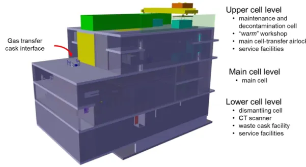
The following picture shows the configuration of the hot cells at the end of the P2C phase.
FIG. 1. Arrangement of the hot cells at the end of the P2C phase. (second step phase of the CAO design process).
The facility consists of 3 levels, with a Main cell, where the NDE equipment are installed and which acts as an interface with the ASTRID fuel handling route, the Lower cells with the dismantling unit and the X-ray scanner device, and finally the Upper cell which serves as maintenance facility and as an airlock for handling functions.
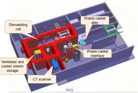
4.1 The Lower cells
The basic requirement of the hot cells is to be able to dismantle all core objects for: ● processing of ruptured fuel pins,
● waste conditioning purpose (absorber assemblies), ● experimental analysis,
● troubleshooting operations.
In that aim, a dedicated dismantling cell with a versatile robotic dismantling unit is foreseen in the Lower cells. The preliminary design of the dismantling unit is to be performed in the next engineering phase. A particular challenge in this context is the cooling of the spent fuel sub-assemblies by forced gas circulation during the dismantling process.
The Lower cells will also house an X-ray scanner device (2nd generation tomography scanner, featuring a 9 MeV accelerator X-ray source and multi detector array) for an accurate and high-precision 3D-scan of the fuel pin bundle before dismantling of the sub-assembly.
FIG. 2. Simulation of X-ray tomography rendering. (horizontal cross section of fuel sub-assembly)
This level will also contain the ventilated and cooled interim storage as well as the alley and parking position of the waste gasket, both accessed via the Main cell.
FIG. 3. Arrangement of the Lower cell at the end of the P2C phase. (second step phase of the CAO design process)
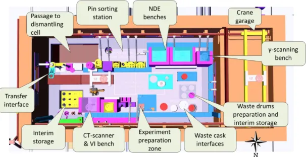
4.2 The Main cell
FIG. 4. Arrangement of the Main cell. (second step phase of the CAO design process)
The Main hot cell hosts all the processes for the main purposes of the ASTRID hot cell, consisting of non-destructive examinations on the spent core sub-assemblies, fuel pins and test capsules, and the preparation of irradiation tests.
The following table details the examinations to be performed by the different workstations:
TABLE 1: EXAMINATIONS TO BE PERFORMED IN THE MAIN CELL.
The examinations posts dealing with the dimensional measurements of small and medium-sized objects is doubled for reasons of redundancy, considering the number of objects to be examined, and to adapt to the size of the objects.
The Main cell is also the main hub for the handling of the irradiated objects. Arriving via the interface with the gas transfer gasket in the eastern part of the cell, the objects are dispatched to the NDE stations, the interim storage or the dismantling cell. Waste drums are conditioned in the western part of the cell and evacuated via the waste cask interfaces.
A particular feature of the Main cell is the crane garage, situated at the western extremity of the cell and overarching the operator area. This mezzanine-like vault, which can be separated from the Main cell volume by an airtight door, houses the crane when it is not used, in order to protect it from unnecessary radiation exposure. Moreover, it serves as an air-ventilated maintenance room for the crane components, as it can be accessed through a hatch from the Upper cell.
FIG. 5. Arrangement of NDE workstations in the Main cell. (second step phase of the CAO design process)
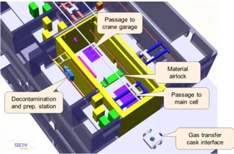
4.3 The Upper cell
The Upper cell will serve as an airlock area for handling functions, ie. the transfer of heavy loads toward the Main cell. It can therefore be ventilated by breathable air or inerted with nitrogen gaz. It contains also a decontamination cabinet to process equipment which needs to be removed from the hot cells for maintenance. Certain maintenance and assembly activities can also be performed in the adjacent room, designated as a “warm” workshop.
Moreover, the Upper cell provides access to the garage of the main hot cell crane. The access from the Upper cell allows for maintenance or repair works to be carried out on the crane without the need to take its components out of the hot cell.
FIG. 5. Arrangement of the Upper cell. (second step phase of the CAO design process)
The roof of the Upper cell features another airlock structure which allows for the transfer and the insertion of heavy packages (5 x 2 m, up to 5 tons) into the Upper cell.
FIG. 7. Arrangement of the roof of Upper cell. (second step phase of the CAO design process)
5. Remote operations
The ASTRID hot cells will feature remote operation of NDE equipment and handling processes with new generation manipulators with electric master arms using haptic technology. SEIV considers the use of the technology based on the TAO 2000 software proprietary from CEA LIST, which also assists SEIV in this design work.
The robotic systems are based on new remote handling technology (see references [4] and [5] for more details) and will be controlled from a remote operation room, outside the radiation protection area.
This design aims to minimize of the use of expensive lead shield windows, increase handling capabilities and improve operator ergonomics. The applied design is a mixed concept which will use conventional lead windows as back-up and for safety reasons.
The use of high definition vision by radiation-resistant cameras will be necessary for this mixed concept.
6. Other specific engineering and R&D topics
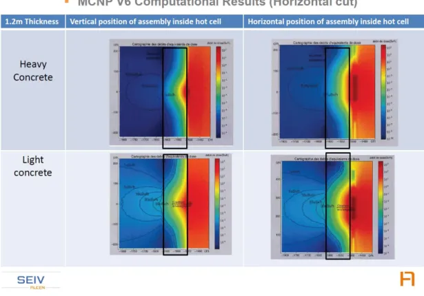
Radiation shielding thickness design has been engaged with the use of the Monte Carlo code MCNP (provide by OAKRIDGE French company).
This software was used to perform the radiation simulation in order to estimate radiological doses for operators surrounding the hot cell concrete with an assembly just located behind it. The following pictures show examples of computational results for a 1.2 m thick hot cell wall made of “heavy” or “standard” concrete.
FIG. 8. MCNP dose computational results for “heavy” or “light” concrete behind a 1.2m thick hot cell wall.
The results of these studies will be used to dimension a save and cost-efficient shielding. For the civil engineering of the hot cells, the use of mixed steel-concrete structures is envisaged. The preliminary HVAC design (see safety analysis aspects in paragraph § 2.) has been also conducted by SEIV. Two kind of atmosphere flows are to be regulated and controlled by the COI HVAC systems: air atmosphere for the areas where operators has to operate and nitrogen atmosphere for the Main and the Lower hot cells areas. Areas for operators of the hot cell building are multi-zoned so that air flows from the less potentially contaminated zones to the more contaminated zones (these potentially contaminated areas are located near the hot cell
walls and in the hot cells). The multi zoned areas of the hot cell building are divided in C2 zone area, C3 zone area and C4 zone areas. (the C2, C3 and C4 classifications are based on International Standard ISO 17873, and must be chosen as a function of the potential contamination level).
The air or nitrogen handling and conditioning units with the associated control system have a major safety function: the HVAC system must be sufficient to provide the necessary degree of contaminant dilution, filtration and cooling, and a sufficient pressure differentials between zones must to be maintained to reach a sufficient dynamic confinement. Based on the preliminary design study, the necessary flow rate to be extracted by the air units is expected tp be around 77 000 m3 per hour (this value is a result of chosen values for the air change rate
and the volume determined by preliminary CAD of the areas). During normal operations, the preliminary design forecasts a closed loop for the recirculated nitrogen-gaz atmosphere through the main and the lowers cells. The closed loop (green coloured pipe in the following figure) must continuously cool and purify the nitrogen atmosphere in order to maintain the specified limits on oxygen and water vapour (under 2%). All the internal surfaces of the nitrogen cells are clad with stainless steel (about 4 mm) in order to reach a leakage rate of less then 2.5·10-3 for volume per hour. With this leakage rate performance, a flux of new nitrogen
of about 80 m3 per hour will be necessary.
For safety reasons the handling and cleaning units have to be duplicated and installed in separated areas, and this fact increase the necessary area to be used by the HVAC systems in the hot cell building. The following CAD image shows the preliminary design (the picture shows in right side air handling and air cleaning redundant units for C4, C3 and C2 areas, and the nitrogen supply systems (green coloured pipes), incoming fresh air stack and extract stack) .
FIG. 9. Arrangement of the HVAC systems. (second step phase of the CAO design process)
7. Conclusion
The ASTRID reactor will be equipped with a hot cell facility in order to fulfil its role as technological demonstrator and R&D testbed. The hot cell facility will feature an extensive set of Non Destructive Examination resources, allowing for rapid on-site PIE evaluations of the innovative materials and components to be tested in ASTRID.
The pre-conceptual design studies have led to a three level layout and the implementation of innovative technology, as the use of motor driven remote handling arms.
The detailed design studies to be undertaken in the current Basic Design Phase of the ASTRID project will concentrate on specific design challenges, as the handling and the dismantling of fuel assemblies with high residual power. Dedicated safety studies will assure the adequacy of the hot cell safety dispositions with the ambitious safety standards of the ASTRID project.
References
[1] The Astrid Project and Related R&D On Na Technology. Magneto hydrodynamics (0024-998X) Jul-Sept 2015 Vol 51 Issue 3 p 485-494
[2] Status of ASTRID architecture in starting of Basic Design phase, Proceedings of ICAPP 2017, April 24-28, 2017 - Fukui and Kyoto (Japan) , to be published
[3] The fuel handling route of ASTRID at the beginning of the basic design, FR17 IAEA International conference on Fast Reactors and Related Fuel Cycle, June 26-29 2017, Yekaterinburg (Russian Federation), to be published
[4] Evaluation tests of the tele-robotic system MT 200-TAO in AREVA-NC La Hague Hot cells. European Nuclear Conference (ENC 2007) 16-20 September 2007.
[5] Operating gains achieved by a new generation of remotely controlled manipulators. Proceedings of the European Nuclear Conference. May 2014