Publisher’s version / Version de l'éditeur:
Vous avez des questions? Nous pouvons vous aider. Pour communiquer directement avec un auteur, consultez la première page de la revue dans laquelle son article a été publié afin de trouver ses coordonnées. Si vous n’arrivez pas à les repérer, communiquez avec nous à PublicationsArchive-ArchivesPublications@nrc-cnrc.gc.ca.
Questions? Contact the NRC Publications Archive team at
PublicationsArchive-ArchivesPublications@nrc-cnrc.gc.ca. If you wish to email the authors directly, please see the first page of the publication for their contact information.
https://publications-cnrc.canada.ca/fra/droits
L’accès à ce site Web et l’utilisation de son contenu sont assujettis aux conditions présentées dans le site LISEZ CES CONDITIONS ATTENTIVEMENT AVANT D’UTILISER CE SITE WEB.
Procedia Manufacturing, 48, pp. 570-578, 2020-06-23
READ THESE TERMS AND CONDITIONS CAREFULLY BEFORE USING THIS WEBSITE. https://nrc-publications.canada.ca/eng/copyright
NRC Publications Archive Record / Notice des Archives des publications du CNRC :
https://nrc-publications.canada.ca/eng/view/object/?id=93f173c8-65dd-4055-9107-82706aab9255
https://publications-cnrc.canada.ca/fra/voir/objet/?id=93f173c8-65dd-4055-9107-82706aab9255
NRC Publications Archive
Archives des publications du CNRC
This publication could be one of several versions: author’s original, accepted manuscript or the publisher’s version. / La version de cette publication peut être l’une des suivantes : la version prépublication de l’auteur, la version acceptée du manuscrit ou la version de l’éditeur.
For the publisher’s version, please access the DOI link below./ Pour consulter la version de l’éditeur, utilisez le lien DOI ci-dessous.
https://doi.org/10.1016/j.promfg.2020.05.084
Access and use of this website and the material on it are subject to the Terms and Conditions set forth at
Reduction of cutting forces by elliptical vibration in multi-pass
ultraprecise single point axial cutting of V-grooves
Farrus, Nikolai; Joao, Delfim; Milliken, Nicolas; Tutunea-Fatan, O. Remus;
Bordatchev, Evgueni
ScienceDirect
Available online at www.sciencedirect.com
Procedia Manufacturing 48 (2020) 570–578
2351-9789 © 2020 The Authors. Published by Elsevier B.V.
This is an open access article under the CC BY-NC-ND license (http://creativecommons.org/licenses/by-nc-nd/4.0/) Peer-review under responsibility of the Scientific Committee of the NAMRI/SME.
10.1016/j.promfg.2020.05.084
10.1016/j.promfg.2020.05.084 2351-9789
© 2020 The Authors. Published by Elsevier B.V.
This is an open access article under the CC BY-NC-ND license (http://creativecommons.org/licenses/by-nc-nd/4.0/) Peer-review under responsibility of the Scientific Committee of the NAMRI/SME.
ScienceDirect
Procedia Manufacturing 00 (2019) 000–000 www.elsevier.com/locate/procedia
2351-9789 © 2019 The Authors, Published by Elsevier B.V.
Peer review under the responsibility of the scientific committee of NAMRI/SME
48th SME North American Manufacturing Research Conference, NAMRC 48, Ohio, USA
Reduction of cutting forces by elliptical vibration in
multi-pass ultraprecise single point axial cutting of V-grooves
Nikolai Farrus
a,b, Delfim Joao
a,b, Nicolas Milliken
b,a,
O. Remus Tutunea-Fatan
a,b*, Evgueni Bordatchev
b,a*
aWestern University, 1151 Richmond St, London N6A 3K7, Canada bNational Research Council of Canada, 800 Collip Cir., London N6G 4X8, Canada* Corresponding author. Tel.: +1-519-661-2111 ext. 88289; fax: +1-519-661-3020. E-mail address: rtutunea@eng.uwo.ca Tel.: +1-226-688-5604; fax: +1-519-430-7064. E-mail address: Evgueni.Bordatchev@nrc-cnrc.gc.ca
Abstract
Elliptical vibration cutting (EVC) is an advanced micromachining technology that has a wide range of applications in high-precision micro/nano manufacturing. This technology is primarily used in fabrication of micro/nano-scale functional surfaces, geometrical features, optical and holographic components that are cut in ferrous and difficult-to-cut tooling materials with high form accuracy and surface quality. The main objective of this study was to demonstrate the positive effect of EVC motions on cutting force reduction and stabilization. For this purpose, a series of cutting trials involving the fabrication of micro V-grooves by means of the ultraprecise single point cutting (USPC) were performed. To maintain a constant level of the cutting force, an axial multi-pass cutting strategy with constant cutting area was employed. The influence and advantages brought by EVC over the conventional ‘no-EVC’ USPC scenario were initially assessed by means of the theoretical considerations of the cutting force. Following that, experimental generation of V-grooves has demonstrated that the integration of EVC kinematics with USPC motions has the ability to reduce the ‘no-EVC’ cutting forces by more than 90%, to values around 0.1 N for the main axial component. The addition of EVC motions caused a minimal decrease in surface quality whose areal roughness increased from 14 nm in the ‘no-EVC’ case to 16 nm in the ‘with-EVC’ scenario. These observations are expected to open new opportunities in micromachining of micro/nano products, systems, sensors, functional surfaces, and lighting and holographic optics.
© 2019 The Authors, Published by Elsevier B.V.
Peer review under the responsibility of the scientific committee of NAMRI/SME
Keywords: Single point cutting; elliptical vibration cutting; V-groove microfabrication; constant cutting area; cutting process; cutting force level
1. Introduction
V-grooves are plain geometrical features that play a critical functional role in a wide variety of industrial applications covering uniform area illumination and light guiding optics in automotive lighting [1], conventional Fresnel lenses [2], optical concentrators and sunlight trapping structures for solar energy harvesting [3], surface functionalization for controlled wettability [4], and aerodynamics [5]. These functional parts and surfaces are typically manufactured at mass production rates and over large area surfaces and therefore steel tooling (inserts, dies, molds, stamps, etc.) is required. Microfabrication of V-grooves with high accuracy, precision and surface quality
has been demonstrated in the past [6] but it is typically limited to non-ferrous materials using rotational and non-rotational diamond cutting tools and high precision processes such as diamond drum turning [7], single point cutting [8],[9], micromilling [10], flycutting/raster milling [11], and planning [12]. Workpiece material limitations have been surpassed through the introduction of EVC that also enables the fabrication of V-grooves, micro/nano-optical structures and functional surfaces in ferrous tooling steel and alloys, difficult-to-cut, ceramic, fragile and exotic materials [13]. In addition to these applications, EVC has also been shown to be applicable to the non-painting coloration of surfaces [14], microfluidic surface structures [15] as well as mirror surface finishes [16].
48th SME North American Manufacturing Research Conference, NAMRC 48 (Cancelled due to COVID-19)
Nikolai Farrus et al. / Procedia Manufacturing 48 (2020) 570–578 571
2 Author name / Procedia Manufacturing 00 (2019) 000–000 The microfabrication of V-grooves across flat surfaces is a
relatively newer area of research that is primarily concerned with the reduction of cutting forces as well as enhancements of surface structure accuracy and quality. By contrast, only few studies are directly focused on more practical aspects of cutting process optimization to include chip formation [17], variations in the elliptical cutting locus and excitation frequency [18], critical depth-of-cut (DoC) [19], and V-groove cutting process planning [20]. In this regard, it was already shown that the EVC process changes the shear flow inside the chip and concurrently reduces cutting forces (by 10% at 65 kHz), chip thickness and chip radius of curvature [17]. Furthermore, significant improvements in the form accuracy of burr-free micro V- grooves can be achieved by means of low cutting forces, particularly since EVC suppresses the plastic deformation of the workpiece. A non-contact index involving the vibration amplitude of the elliptical locus, the feed speed and the excitation frequency was introduced [18] to define a contact/no-contact cutter-workpiece cycle. EVC process was also studied with different values of the non-contact index and it was found that the surface roughness in the feed direction is proportional to the vibration amplitude in the thrust direction and the square of the feed speed. DoC plays a critical role in obtaining a stable cutting state, resulting in a continuous chip [19]. This can be achieved with a minimum (critical) DoC analyzed with respect to (wrt) a cutting force ratio (Fx/Fy), chip
shape, surface roughness and surface hardening. The complexity of EVC process significantly increases during cutting V-grooves by means of multi-pass process planning [20], [21], [22]. During multi-pass EVC, it is important to recognize and pay attention to changes in cutting force components (principal, thrust, and friction) that are affected by a contact area that is unevenly distributed across cutting edges. By taking this into account, EVC process stability and effectiveness can be implemented either with a constant DoC or with a constant cutting area that is essentially targeting a constant cutting force level.
This study exemplifies the capabilities of USPC [21], performed by means of a monocrystalline diamond tool as used during the multi-pass micromachining of high-accuracy V-grooves characterized by an optical surface quality. In this regard, the effect of elliptical vibrations on cutting force reduction will be investigated in the context of an axial cutting strategy performed with constant cutting area.
2. Axial strategy for single point cutting of V-grooves with constant cutting area
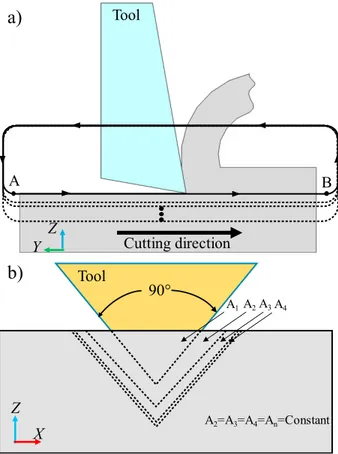
The axial cutting strategy utilized in this work consists of an axially-moving cutting tool that gradually plunges into the workpiece material at a constant/pass cutting area. An overview of the cutting kinematics of this strategy is shown in Fig. 1. During V-groove fabrication, every cutting pass is run across the workpiece with a specific-to-pass depth in –Z direction until the final desired DoC was achieved (Fig. 1a). As the name of the strategy implies, while cutting area remains constant, the depth of cut and chip thickness will follow an inverse proportionality dependence. This means that in order to
fulfill the constant cutting area constraint, the cutting force will be distributed over the lateral edges of the tool (Fig. 1b).
Fig. 1. Cutting kinematics of V-groove fabrication via USPC: a) single-passes along Y direction, and b) multi-passes in -Z direction.
The motion tracked by the single point cutting tool in this cutting process is characterized by a rather low complexity. In brief, the tool plunges in the –Z direction to the desired DoC and then moves across the workpiece in the –Y direction at a constant feed rate and DoC until it reaches the end of the toolpath. Here, the tool lifts above the workpiece and returns to its starting position, readying itself for the next pass (Fig. 1a). This cycle is repeated for a desired number of tool passes until the final depth of the groove is achieved.
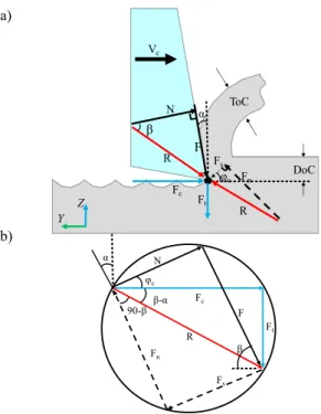
A fundamental theoretical approach that was used to investigate the cutting mechanics of USPC involves Merchant’s circle [23] (Fig. 2). This model describes the cutting force components developed at the chip-tool interface. It should be noted here that the Merchant’s diagram is primarily applicable to orthogonal cutting processes in which the rake face is the only face of the tool is in contact with the workpiece. The constant cutting area USPC strategy used in V-groove fabrication involves an additional contact on the flanks of the cutting tool, such that Merchant’s model must be modified in order to sufficiently capture cutting force (CF) generation accurately.To utilize the orthogonal CF model for V-groove fabrication, cutting edge has to be discretized into small elements, each representing an instance of a micro-orthogonal cutting process. Following this, each elemental section could
A
B
Cutting direction
Z
Y
Tool
a)
b)
Z
X
90
A1A2A3A4 A2=A3=A4=An=ConstantTool
then be solved individually by means of the original Merchant’s circle method. Finally, the combination all such discrete instances will provide an accurate general CF model.
In this context, the CF model is completed by analysing reaction force components at the tool/workpiece interface. While force component magnitudes and directions are ultimately a result of the shear strain rate and the material properties, these effects can also be influenced through the cutting parameters used. Essentially, the CF diagram can be split into two components, one driven by the axial tool motion (characterized by the cutting speed Vc) and the other by the
shear properties of the workpiece material.
Fig. 2. Cutting forces in conventional cutting: a) forces developed at tool/ workpiece interface, and b) Merchant’s circle for free orthogonal cutting.
When it comes to CF, tool kinematics are characterized by user-controlled variables such as the cutting speed of the tool (Vc) and the depth of cut (DoC), i.e., blue vectors in Fig. 2.
Principal cutting (Fc) and thrust (Ft) forces can be defined as
the primary forces required to overcome the friction force F, as well as the shear force (Fs) that oppose tool motion direction.
The accurate determination of Vc and DoC has a large effect on
the magnitude of cutting and thrust forces developed during cutting. However, an additional level of control could come from tool geometry itself, more specifically rake angle (α). This angle tends to have a large influence on the orientation and magnitude of the force.
On the other hand, CF model is also influenced by tool-workpiece interaction via shear deformation properties of the material. To explain this, it will be reiterated here that rake angle is crucial when it comes to both cutting force and shear components of the CF circle diagram. More specifically, the rake angle defines/determines the direction of the frictional force (F), except F runs in a direction that opposes chip motion (Fig. 2). Following this, the resultant force R can be defined as the vectoral sum between F and N (a normal to F force). As
suggested by Fig. 2, R constitutes the common element between the CF and shear deformation halves of the circle. The shear deformation-driven CF triangle is geometrically determined by the resultant R and shear angle φ, from which the shear force (Fs), is determined (black dashed lines in
Fig. 2).
All these considerations allow the determination of both cutting (Fc) and trust (Ft) force components. In more general
terms, the forces produced through the conventional cutting of micro V-grooves (Fcc) are dependent on the cutting coefficient
(K) as well as the constant nominal cutting area (Ac). According
to prior studies [24] [25], cutting coefficient is dependent on the cutting speed (Vc), depth of cut (DoC), rake angle (α), and
constant nominal cutting area (Ac).
( ,c , ) c
CC
F K V DoC A (1)
3. Integration of EVC mechanics with single point cutting The cutting force models associated with the EVC process add another level of complexity to the conventional Merchant’s diagram by essentially incorporating the time-dependence. While Vc, DoC, α and other cutting parameters described in the
preceding section remain constant, the addition of the ultrafast elliptical motion and its inherently interrupted contact introduce another layer of complexity to the CF analysis.
In the “with EVC” case, the major source of cutting force reduction is represented by the intermittent contact between tool and material. This type of interaction is repeated for each elliptical revolution of the tool, a motion fully contained in the vertical plane. During each elliptical revolution, the duration of the disengaged phase has beneficial effects not only on the magnitude of the CF, but also on chip removal as well as heat dissipation.
The elliptical motion of the cutting tool can be described as follows:
( ) c y cos(2 )
y t V t A t (2)
( ) z sin(2 )
z t A t (3)
Where Ay and Az are bending and longitudinal amplitudes,
respectively.
The additional complexity brought by EVC on Merchant’s diagram can be explained by means of the two phases associated with the elliptical cutting cycle: conventional kinetic friction zone and reversed friction zone [26]. As shown in Fig. 3, these two distinct phases are tightly connected with the elliptical path of the tool.
During the first stage, the conventional kinetic friction zone occurs from point A of contact between the tool and workpiece and lasts until C, where cutting and frictional force oppose each other, same as in conventional cutting (Fig. 4). The second phase starts from point C and lasts until D, where tool disengages from the workpiece (Fig. 5). This latter phase is associated with the reversed friction zone where both frictional (F) and cutting (Fc) forces have somewhat similar directions.
ToC DoC Fn R Fs R φ β α N F Fc Ft Vc Z Y b) a) Fs Ft Fc R N F Fn α φ β β-α 90-β
Nikolai Farrus et al. / Procedia Manufacturing 48 (2020) 570–578 573
4 Author name / Procedia Manufacturing 00 (2019) 000–000
Fig. 3. The two EVC phases/tool motion intervals: 1) kinetic friction zone (A to C) and 2) reversed friction zone (C to D).
This situation is a consequence of the fact that tool motion happens in the direction of the chip that is being formed. As such, it appears that cutting force reductions are the result of both the diminished contact time between tool and workpiece as well as the change/reversal of frictional force direction.
Fig. 4. Cutting forces in the kinetic friction phase of EVC: a) forces developed at tool/ workpiece interface, and b) revised Merchant’s circle.
Fig. 5. Cutting forces in the reversed friction phase of EVC: a) forces developed at tool/ workpiece interface, and b) revised Merchant’s circle.
To elaborate a bit further, it is reasonable to expect that the overall average cutting force will be reduced when EVC is active since the tool is only intermittently in contact with the workpiece for each elliptical revolution of the tool. Nevertheless, additional cutting force reductions can be inferred from the direction of cutting force components and they are the result of the aforementioned reversal in the direction of the frictional force that is in turn a consequence of the upward motion experienced by the tool when travelling between C and D. In other words, if cutting force patterns during the kinetic friction phase are more or less similar with those in conventional cutting, significant dissimilarities exist in the reversed friction phase.
As such, the resulting cutting force equations can be expressed through the introduction of a transient force equation that captures the orientation of the force vectors in kinetic friction, transition and reverse friction zones:
, ( , , , ) EVC c cc EVC F K V DoC f A A (4) 0,0 , total A AL B A A A (5) 0,0 , total A AL B
DoC DoC DoC
(6) According to Eq. 4 - 6, cutting forces developed during the cutting of micro V-grooves depend on cutting speed (Vc), depth
of cut (DoC), EV frequency (f), rake angle (α), nominal constant cutting area (Acc), as well as the variable cutting area
(AEVC). Acc represents the constant cutting area determined
through the conventional/non-EVC cutting process, whereas AEVC is based on the cyclical motion introduced by EVC and
varies throughout the elliptical period (Fig. 3). In this study, to maintain a constant cutting area, DoC0,0 has to be different for
B A C D ToCt Z Y α b) a) ToC DoC Fn R Fs R φc β α N F Fc Ft Vc Z Y Fs Ft Fc R N F Fn α φc β β-α 90-β a) b) ToC DoC Fn R Fs R φR β N α F Fc Ft Vc Z Y α F N Fc Fs Ft Fn φR R β
each pass, such that the ratio between Acc and AEVC also changes
at each pass (Fig. 3). However, the incremental change in the depth of cut (ΔDoC) with respect to the previous pass remains consistent between the no-EVC and with-EVC experiments. 4. Experimental set-up and data processing methodology
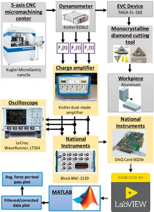
In order to measure, record and analyze the actual cutting force components over time and space domains, a previously developed experimental set-up [21] was augmented to enable experiments with integrated EVC motions, (Fig. 6). The experimental set-up is based on a high-performance/high-precision multi-process 5-axis micromachining center MicroGantry nano5x manufactured by Kugler GmbH. The EVC unit EL-50Σ from TAGA Electric Co., Ltd. was mounted vertically on Z axis with ability to move only along Z axis. Bending and longitudinal elliptical vibrations of the cutting tool tip were fully controlled by means of an electrical controller and power amplifiers.
The workpiece, made of aluminum alloy 6061, was mounted onto the Kistler 9256C-2 dynamometer attached to a tilt-swivel unit of the 5-axis micromachining center allowing four-axis motions of the workpiece. During cutting experiments, the tool performed a total number of 44 passes across the 10 mm long workpiece until a final DoC of 250 µm was obtained. For each cutting pass, all parameters listed in Table 1 were kept constant with the exception of the DoC0,0, that varied to maintain a
constant cutting area (Fig. 1). DoC0,0 for each pass was
calculated by means of trigonometric formulas presented in [22]. Spatial cutting force components {FX(t), FY(t), FZ(t)}
were measured by the dynamometer for each pass and were subsequently converted into corresponding electrical signals by three Kistler 5010 dual mode charge amplifier (one amplifier per cutting force component). After that, these electrical signals were digitized by a National Instruments 6023e data acquisition card with a sampling frequency of 2 kHz and saved onto a computer for further data processing.
The time-dependent cutting force components {FX(t), FY(t),
FZ(t)} were initially filtered by means of a MATLAB software
and in-house developed post-processing script. To investigate the quasi-static components of the cutting forces, a Matlab-based moving-average low-pass filter was used to filter/smooth the acquired data. The window size was set at 200 data points and with a frequency of 2 kHz, essentially matching the sampling rate of the DAQ. Furthermore, the linear drift introduced by the charge amplifier was eliminated from the data for each of the cutting force components. Finally, the digital signature of the cutting force components were separated with respect to individual tool motions/passes and then average cutting forces per pass were calculated.
The main objective of the EVC experiments performed in the context of this study was to investigate the influence of elliptical vibrations on the cutting force developed during the multi-pass fabrication of V-grooves. Therefore, cutting experiments were performed both ‘with’ and ‘without’ EVC motions active. The axial V-groove cutting strategy with constant area was intentionally selected to ensure a high repeatability of the experimental results with respect to the desired constant/quasi-constant cutting forces.
Fig. 6. Experimental setup and data processing workflow.
A triangular-shaped monocrystalline single point diamond cutting tool was used for experiments (Fig. 7). The cutting tool had an included angle of 90°, a rake angle of 0°, and a clearance angle of 10°. The 90° included angle allowed the fabrication of axially symmetric V-grooves characterized by a symmetric cutting area shape and thereby symmetric cutting forces across the cutting face. A special attention was dedicated to the clearance angle of 10° since it introduces a limitation in the selection of the EVC parameters (e.g. longitudinal and bending amplitudes). More specifically, the clearance angle limits the magnitude of the cutting speed in order to avoid a frictional contact between the flank face of the cutting tool and that of the cut surface.
Fig. 7. Triangular monocrystalline single point diamond cutting tool. Dynamometer Kistler9256c2 EVC Device TAGA EL-50Σ Workpiece Aluminum MATLAB Filtered/corrected data plot Avg. force per tool
pass plot 5-axis CNC micromachining center Kugler MicroGantry nano5x Monocrystalline diamond cutting tool Oscilloscope LeCroy WaveRunner, LT354 Fz(t) Fx(t) Fz(t) Charge amplifier Kistler dual-mode amplifier National Instruments Block BNC-2110 National Instruments
Nikolai Farrus et al. / Procedia Manufacturing 48 (2020) 570–578 575
6 Author name / Procedia Manufacturing 00 (2019) 000–000 5. Cutting forces during multi-pass micromachining of
V-grooves performed with and without EVC motions Several V-groove cutting trials were performed with and without the use of EVC process in order to compare actual cutting forces and their quasi-dynamics. However, the machining parameters used for this study’s analysis are presented in Table 1.
Table 1. Cutting trial parameters.
Parameter Value
Feed rate (mm/min) 500
Final chip thickness (µm) 2
Vibrational frequency (kHz) 41
Final depth of cut (µm) 25
Groove length (mm) 10
DoC0,0 Varies for each pass
Longitudinal amplitude, AZ
(µm) 2
Bending amplitude, AY (µm) 6
Rake angle (α) 0°
Workpiece material Aluminum alloy 6061
Coolant Isoparaffin mist
The pre-trial surface of the sample was brought to an ultra - finished state by means of diamond cutting in order to ensure its planarity and quality, two important prerequisites for the repeatability of the tests to be performed. The peak-to-valley waviness of the surface was assessed to be below 400 nm. The sample was aligned with a cutting direction (by enforcing an under 0.5 μm deviation) to ensure a uniform DoC along each cutting pass. In addition, V-grooves were placed more than 500 μm from each other in order to avoid confounding effects caused by deformations of the lateral V-groove walls.
To analyze average cutting forces, a mid-depth V-groove pass was used (i.e., pass 22 of the total 44 passes required to generate the entire V-groove). This selection ensured a stable cutting regime and thereby the acquisition of reliable data. The analyzed pass was characterized by DoC0,0 = 4 μm and
DoCAL,AB = 1 μm. The EVC amplitudes were set as AY = 6 µm
and AZ = 2 µm. These values were based on a number of
anterior trials attempting to determine the combination of amplitudes yielding larger/more significant CF reductions.
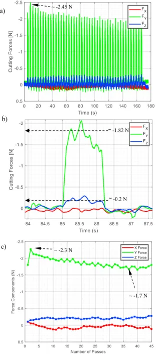
The first experiment fabricated the V-groove in absence of EVC. The representative result presented in Fig. 8 demonstrates the evolution of the cutting force during the consecutive machining passes. Of note, the first cutting pass, denoted by the average force of ~2.3 N, Fig. 8(c), was not taken into consideration since it was regarded as more of an alignment/engagement – pass.
One important observation to be made is related to the correlation between the behavior presented in Figs. 8(a) and 8(c). As suggested by Fig. 8(a), FY,2 reaches a maximum value
for the second pass and all subsequent passes exhibit a quasilinear reduction trend: FY,2 < FY,3 < FY,4 < … < FY,n.
Fig. 8. Evolution of cutting forces during non-EV V-groove cutting: a) multiple successive passes, b) single pass, and c) average per machining pass.
Here, FY,n represents the Y component of the cutting force for
the nth cutting pass. Similar notations/meanings were used for
FX,n. and FZ,n. This type of downward trend can be directly
attributed to the redistribution of the principal cutting force component FY,n over the cutting area for each n-th pass, an
activity followed by the gradual reconfiguration of the cutting area from a triangle to a V-shape. Because of the deepening groove, cutting force FY gradually changes its location from the
tip (FY,2) to the sides of the cutting tool (FY,3…n). Because of this,
the friction between the lateral cutting edges and facets of the
~ -1.82 N a) b) c) ~ -2.45 N ~ -1.7 N ~ -2.3 N ~ -0.2 N
V-groove gradually become a more dominating factor on the overall magnitude of FY.
On the other hand, the evolving cutting forces also cause changes in FX and FZ components. As it can be noticed in
Figs. 8(a) and 8(c), FZ,2…n exhibits a somewhat similar but
ascending trend (i.e., opposite to FY,2…n). This is a consequence
of the fact that side friction forces are projected vertically according to the included angle of the V-groove and therefore they will simultaneously reduce FY,2…n. However, their
influence on FY is relatively minimal. On the other hand, the
absent X-axis motions as well as the symmetrical balancing of the horizontal projections of the lateral friction forces can explain the near-zero/negligible average value of FX,2…n. In
other words, FX,2…n and FZ,2…n components remain quite
consistently at (very) small values relative to the main FY,2…n
axial component. The value of the lateral components of the cutting force can be assessed as varying around the noise level. Fig. 8(b) depicts the quasi-dynamic behavior of the cutting force components during a single pass cutting. During each pass, cutting tool contacts the workpiece material with rake face and this causes an initial spike in two of the cutting force components (FY and FZ), but not in the third (FX). The initial
contact bends/deflects the tool. This deformation is gradually released during the stable cutting and this in turn might case the aforementioned linear reduction of FY during the subsequent
passes.
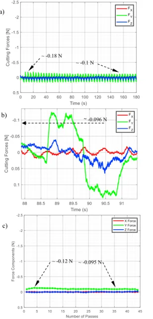
For comparison purposes, a second set of cutting trials was performed with EV motions “on” while preserving all non-EVC cutting parameters, cutting strategy, tool trajectory as well as geometry of the V-groove being cut. As expected, EVC affected the entire cutting mechanics behavior (Fig. 9(a)) that was then comparatively assessed with respect to its non-EVC counterpart.
In brief, it is quite evident that EVC motions significantly reduce all spatial components of the cutting force. For instance, FY was observed to decreased by a variable range above the
92% threshold (i.e., 92.7% for FY,2 and 94.4% for FY,35). The
overall stability of the cutting has also improved significantly since the 26.1% (0.6 N) reduction of FY that is visible in
Fig. 8(c) - with single-pass deviations around ±0.36 N - was replaced with a more stable ‘with’ EVC FY that has decreased
only slightly from FY,2 = -0.12 N to FY,35 = -0.095 N, deviating
from the single-pass average force by ±0.025 N. Owed to these small values, it can be noted here that the apparent fluctuations of the FX and FZ components are in fact comparable to the noise
level of the data acquisition system. This notable improvement was also coupled with significant reductions in the friction process between cutting edges and V-groove facets. These observations also demonstrate that cutting force FY becomes
proportional to the cutting area since it is characterized only by minor deviations (cca ±0.005 N) from its mean value of approximately -0.1 N that spans over the entire multi-pass cutting process. However, is perhaps important to mention here that these values may be within the sensing resolution of the dynamometer and also barely above the noise level.
The validity of the results above is reinforced by the observation that further those seen in the non-EVC scenario, both FX and FZ have in this case negligible values characterized
by minor fluctuations caused by mechanical and electrical noise.
Fig. 9. Evolution of cutting forces during EV V-groove cutting characterized by Az = 2 µm and Ay = 6 µm: a) multiple successive passes, b) single pass,
and c) average per machining pass.
Thus, FX ≈ 0 N simply because EVC suppresses (the majority
of) process-induced cutter-workpiece displacements. Moreover, the following are also plausible: i) the dynamic compliance of the cutting process becomes almost negligible, ii) cutting force coefficient K(∙) becomes constant for this set of machining parameters, and iii) surface topography is solely determined by the elliptical trajectory of the cutting tool tip. For all these reasons, EVC constitutes a valuable enabler of micro/nano-structuring of functional surfaces (e.g. [6], [14]). As shown in Fig. 10, the addition of EVC motions does not decrease surface quality compared to the no-EVC case. This means that in addition to the aforementioned cutting force
a) b) c) ~ -0.096 N ~ -0.18 N ~ -0.1 N ~ -0.095 N ~ -0.12 N
Nikolai Farrus et al. / Procedia Manufacturing 48 (2020) 570–578 577
8 Author name / Procedia Manufacturing 00 (2019) 000–000 reduction, EVC does not have a detrimental effect on surface
quality.
Fig. 10. Surface quality: a)-c) representative no-EVC results, d)-f) representative with-EVC results
The comparative analysis of the quasi-dynamics during single pass cutting without (Fig. 8(b)) and with EV (Fig. 9(b)) suggests both the mechanism and the actual dependence of FZ
and FX on FY. More specifically, Fig. 8(b) implies that FZ
represents nothing but a spatial projection (or ‘spatial echo’) of FY that appears concomitantly but at much smaller amplitude
(FY = 1.82 N vs FZ = -0.2 N). However, when EV is on, no such
definite relationship exists (Fig. 9(b)). This could be a supplementary indication of the indirect effect exerted by high-frequency elliptical motions of tool tip (EVC unit is fixed wrt Z-axis) on low-frequency cutting motions along Y-axis of the workpiece, i.e., along the principal/axial cutting direction of the V-groove.
6. Summary and conclusions
This study was primarily concerned with the investigation of EVC effects on the spatial components of the cutting forces developed during V-groove micromachining. For this purpose, the spatial decomposition of the cutting forces was initially analyzed by means of classical Merchant’s diagram that was particularized both for ‘with’ and ‘without’ EV cutting scenarios. Following these preliminary observations, identical
cutting trials were performed under the same two main scenarios and the following conclusions can be drawn: The addition of high-frequency elliptical vibrations to single
point cutting of V-grooves significantly changes both its cutting dynamics and chip formation mechanism. The main outcome of the EV-augmented V-groove cutting is that it leads to significant (> 92%) reductions of cutting force amplitude.
EVC has an important stabilization effect on cutting forces since they become less dependent on the friction between tool and V-groove facets. This effect is implied by the lack of descending trend in FY (0.6 N to ±0.005 N) during
multi-pass machining of V-grooves.
Elliptical vibrations change the dynamics of the cutting process since the tip moves at high speed with respect to the slow-moving workpiece. This observation is supported by the fact that when EV are on, FZ and FX components have a
minimal effect on FY.
In summary, it is anticipated that these improvements of the V-groove cutting process brought by EVC will open up new opportunities in micromachining of micro/nano products, systems, sensors, functional surfaces, as well as lighting/holographic optics. Furthermore, the results above could constitute the premise of several new scientific directions related to deep learning-based analysis, optimization and control of the cutting-based material removal at micro/nano-scale and/or with optical surface quality.
Acknowledgements
The work presented in this study was the result of the collaboration between Western University (London, Ontario) and National Research Council of Canada (London, Ontario). Partial financial support was also provided by Natural Sciences and Engineering Research Council (NSERC) of Canada. References
[1] Lin, C.-Y., C.-H. Su, C.-M. Hsu, and C.-R. Lin, 2008. Improvement of the microcrystalline cube corner reflective structure and efficiency. Japanese Journal of Applied Physics, 47(7R), pp. 5693.
[2] Chen, Y.-C., S.-C. Nian, and M.-S. Huang, 2016. Optical design of the Fresnel lens for LED-driven flashlight. Applied optics, 55(4), pp. 712-721.
[3] Wei, A.-C., S.-Y. Hsiao, J.-R. Sze, and J.-Y. Lee, 2019. V-groove and parabolic array for enlarging the acceptance angle of a side-absorption concentrated photovoltaic system. Optics & Laser Technology, 112, pp. 426-435.
[4] Luo, Y., Y. Liu, J. Anderson, X. Li, and Y. Li, 2015. Improvement of water-repellent and hydrodynamic drag reduction properties on bio-inspired surface and exploring sharkskin effect mechanism. Applied Physics A, 120(1), pp. 369-377. No EVC EVC (Az= 2μm, Ay= 6μm) Sa= 16.413nm Sa= 14.966 nm 200 x 500µm Planar Removal 120 x 120µm, ISO filter surface roughness 80µm 120 x 120µm, ISO filter surface roughness 80µm 200 x 500µm Planar Removal a) b) c) d) e) f)
[5] Abdulbari, H.A., H.D. Mahammed, and Z.B.Y. Hassan, 2015. Bio-inspired passive drag reduction techniques: A review. ChemBioEng Reviews, 2(3), pp. 185-203. [6] Brinksmeier, E., R. Gläbe, and L. Schönemann, 2012.
Review on diamond-machining processes for the generation of functional surface structures. CIRP Journal of Manufacturing Science and Technology, 5(1), pp. 1-7.
[7] Zhao, Z.L., H.P. Yu, D.M. Wu, Y. Liu, X.T. Zheng, J. Zhuang, et al., 2013. Research on the key technology in ultra-precision machining of optical micro V-groove mold roller. Advanced Materials Research, 712-715, pp. 1563-1567.
[8] Moriya, T., K. Nakamoto, T. Ishida, and Y. Takeuchi, 2010. Creation of V-shaped microgrooves with flat-ends by 6-axis control ultraprecision machining. CIRP Annals - Manufacturing Technology, 59(1), pp. 61-66. [9] Milliken, N., B. Hamilton, S. Hussein, O.R.
Tutunea-Fatan, and E. Bordatchev, 2018. Enhanced bidirectional ultraprecise single point inverted cutting of right triangular prismatic retroreflectors. Precision Engineering, 52, pp. 158–169.
[10] Forfang, W.B.D., T.G. Conner, B.H. You, T. Park, and I.-H. Song, 2014. Fabrication and characterization of polymer microprisms. Microsystem Technologies, 20(10-11), pp. 2071-2077.
[11] To, S. and G. Zhang, 2014. Study of cutting force in ultra-precision raster milling of V-groove. The International Journal of Advanced Manufacturing Technology, 75(5-8), pp. 967-978.
[12] Guo, J., J. Zhang, H. Wang, K. Liu, and A.S. Kumar, 2018. Surface quality characterisation of diamond cut V-groove structures made of rapidly solidified aluminium RSA-905. Precision Engineering, 53, pp. 120-133. [13] Li, Z.J., F.Z. Fang, H. Gong, and X.D. Zhang, 2013.
Review of diamond-cutting ferrous metals. The International Journal of Advanced Manufacturing Technology, 68(5-8), pp. 1717-1731.
[14] Yang, Y., Y. Pan, and P. Guo, 2017. Structural coloration of metallic surfaces with micro/nano-structures induced by elliptical vibration texturing. Applied Surface Science, 402, pp. 400-409.
[15] Guo, P., Y. Lu, K.F. Ehmann, and J. Cao, 2014. Generation of hierarchical micro-structures for anisotropic wetting by elliptical vibration cutting. CIRP Annals, 63(1), pp. 553-556.
[16] Shamoto, E. and T. Moriwaki, 1999. Ultaprecision
diamond cutting of hardened steel by applying elliptical vibration cutting. CIRP Annals-Manufacturing Technology, 48(1), pp. 441-444.
[17] Kim, G.D. and B.G. Loh, 2007. Characteristics of chip formation in micro V-grooving using elliptical vibration
cutting. Journal of Micromechanics and
Microengineering, 17(8), pp. 1458-1466.
[18] Kim, G.D. and B.G. Loh, 2008. Characteristics of elliptical vibration cutting in micro-V grooving with variations in the elliptical cutting locus and excitation frequency. Journal of Micromechanics and Microengineering, 18(2), pp. 025002.
[19] Son, S.M., H.-S. Lim, I.-H. Palk, and J.-H. Ahn, 2003 A study on critical depth of cuts in micro grooving. KSME International Journal, 17(2), pp. 239-245.
[20] Lee, J.-M., T.-J. Je, D.-S. Choi, S.-W. Lee, D. Le, and S.-J. Kim, 2010. Micro grooving simulation and optimization in the roughing stage in the roughing stage. International Journal of Precision Engineering and Manufacturing, 11(3), pp. 361-368.
[21] Joao, D., N. Milliken, E.V. Bordatchev, and O.R. Tutunea-Fatan, 2019. Axial strategy for ultraprecise single point cutting of V-grooves Case 1: constant chip thickness. Procedia Manufacturing, 34, pp. 440-445. [22] Joao, D., N. Milliken, O.R. Tutunea-Fatan, and E.V.
Bordatchev, 2019 One side cutting strategy for ultraprecise single point cutting of v-grooves. Case 2: Constant cutting area. American Society for Precision Engineering (ASPE) Annual Meeting, 71, pp. 325-330. [23] Klocke, F., 2011. Manufacturing Processes 1: Cutting.
Springer.
[24] Kolar, P., P. Fojtu, and T. Schmitz, 2015. On cutting force coefficient model with respect to tool geometry and tool wear. Procedia Manufacturing, 1, pp. 708-720. [25] Kai-Uwe Sattler, D.C.N., Ngoc Pi Vu, Banh Tien Long, Horst Puta, 2019. Advances in Engineering Research and Applications: Proceedings of the International Conference on Engineering Research ans Applications, ICERA 2019, ed. D.C.N. Kai-Uwe Sattler, Ngoc Pi Vu, Banh Tien Long, Horst Puta. Springer.
[26] Bai, W., R. Sun, Y. Gao, and J. Leopold, 2016. Analysis and modeling of force in orthogonal elliptical vibration cutting. The International Journal of Advanced Manufacturing Technology, 83(5), pp. 1025-1036.