1
C
OGNITIVE
T
ASK
A
NALYSIS FOR THE
LCS
O
PERATOR
S.D.
S
COTT
M.L.
C
UMMINGS
MASSACHUSETTS INSTITUTE OF TECHNOLOGY*
PREPARED FOR CHARLES RIVER ANALYTICS
In support of Plan Understanding for
Mixed-initiative control of Autonomous systems (PUMA)
HAL2006-01
JANUARY 2, 2006
*MIT Department of Aeronautics and Astronautics, Cambridge, MA 02139
Executive Summary
The following Tables and Figures detail the cognitive task analysis (CTA) performed to
determine the information requirements needed to support a single operator located aboard the
futuristic Littoral Combat Ship (LCS). This operator is responsible for controlling four
underwater unmanned vehicles in conjunction with a UAV operating on a shared network.
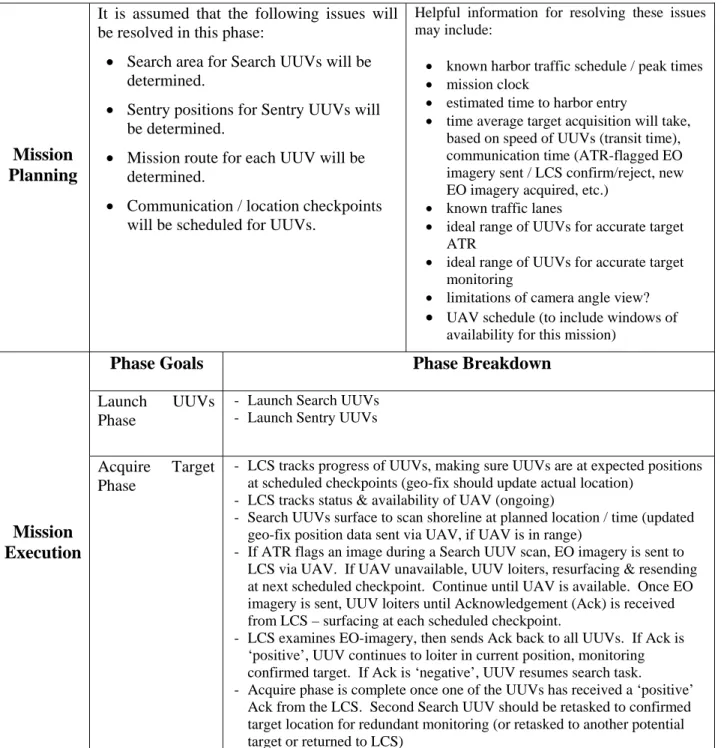
• Table 1 is a scenario task overview that breaks the overall mission into 3 phases
(planning, execution, and recovery) and then details the subtasks for each of the 3
mission phases.
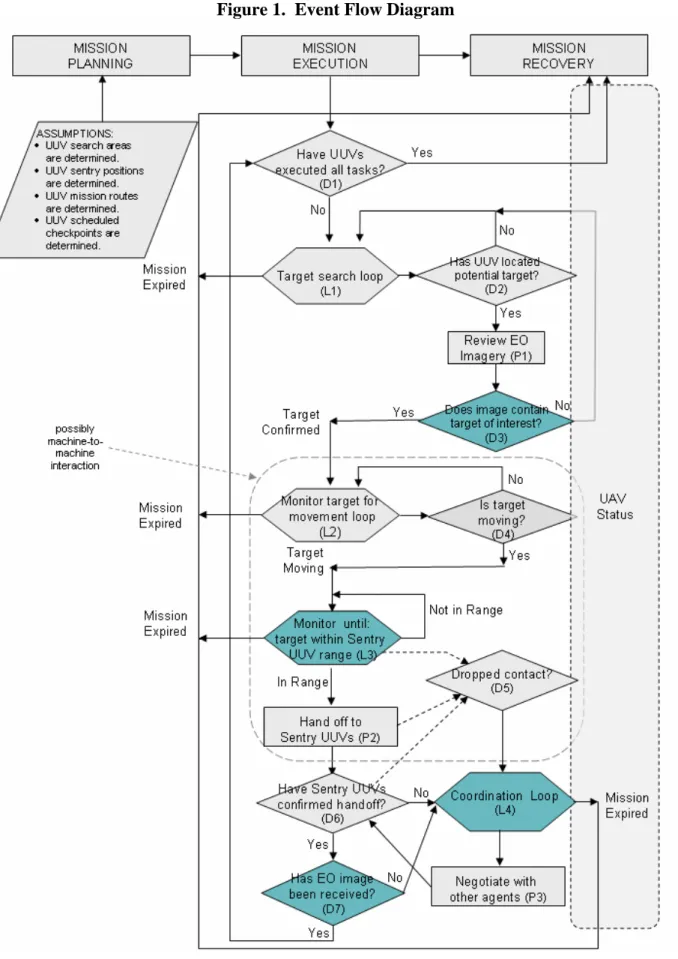
• Figure 1 is an event flow diagram that demonstrates what events must occur in a temporal
order for each of the 3 phases. There are three basic event types in Figure 1: 1) a loop (L)
that represents a process that occurs in a looping fashion until some predetermined event
occurs, 2) a decision (D) that represents some decision that is required from the LCS
operator, and 3) a process (P) which requires some human-computer interaction to
support the required tasks. In each event block, an alphanumeric code is included which
labels that particular event type (L#, D#, P#). This label is important because later
information requirements will be mapped to one of these events.
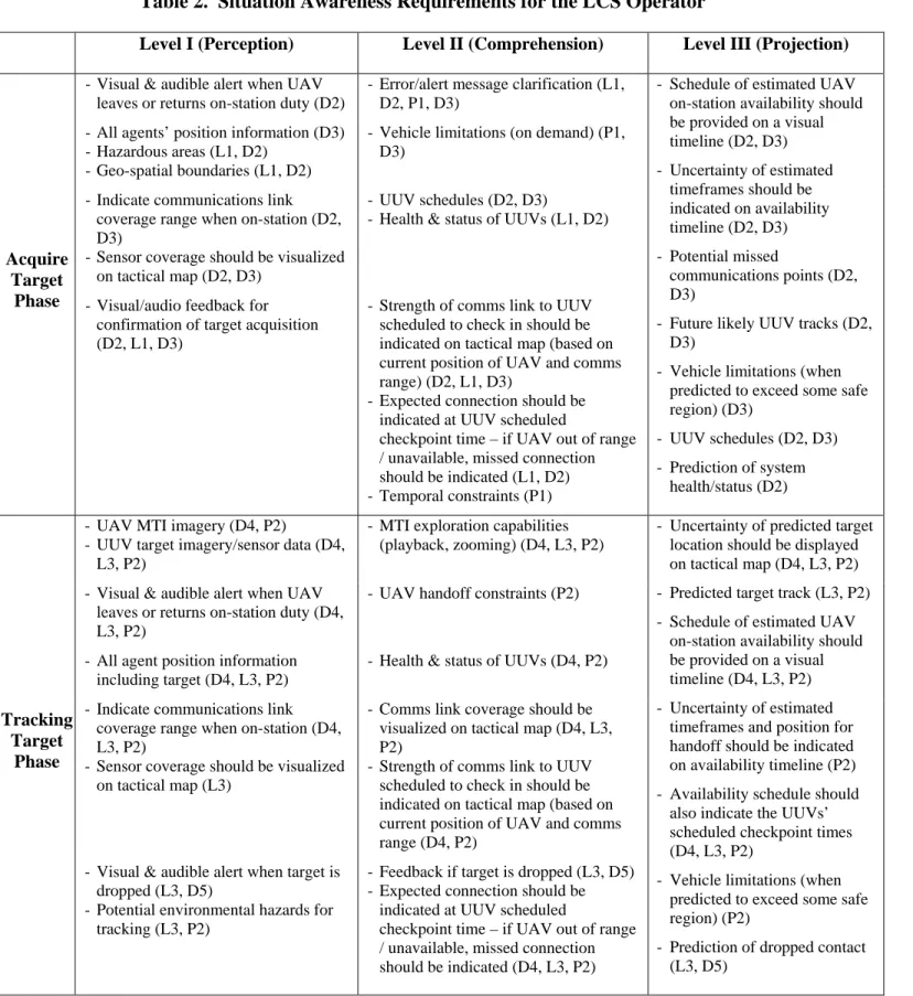
• Table 2, which details the situation awareness (SA) requirements for the LCS Operator
for each of the 3 mission phases and associated subtasks. Each of these SA requirements
is mapped directly to one or more events in Figure 1.
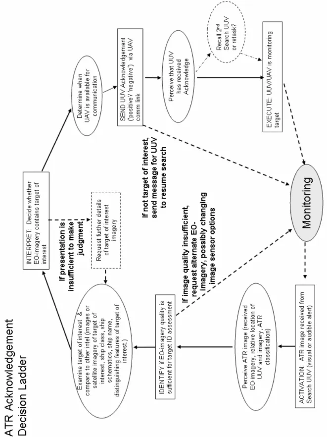
Because the decisions in Figure 1 represent critical events that require detailed understanding of
what information and knowledge is needed to support the operator’s decision-making process,
decision ladders were constructed for the diamonds and loops in Figure 1 that correspond to an
involved decision process to resolve the question being posed at that stage in the event flow
(Figures 2-4). Decision ladders are modeling tools that capture the states of knowledge and
information-processing activities necessary to reach a decision. Decision ladders can help
identify the information that either the automation and/or the human will need to perform or
monitor a task. Decision Ladders, illustrate the need not only for the same information identified
by the cognitive task analysis, but the need for several other pieces of information such as the
need for visual or aural alerts in contingency situations. In Figures 2-4, three versions are
included that detail (a) the basic decision ladder, (b) the decision ladder with corresponding
display requirements, and (c) the decision ladder with possible levels of automation.
• Figure 2 represents the automated target recognition (ATR) decision ladder (D3 from
Event Flow): (a) decision ladder, (b) decision ladder with corresponding display
requirements, and (c) decision ladder with possible levels of automation.
• Figure 3 shows the decision ladder information and knowledge requirements for the
sentry handoff (L3 from Event Flow).
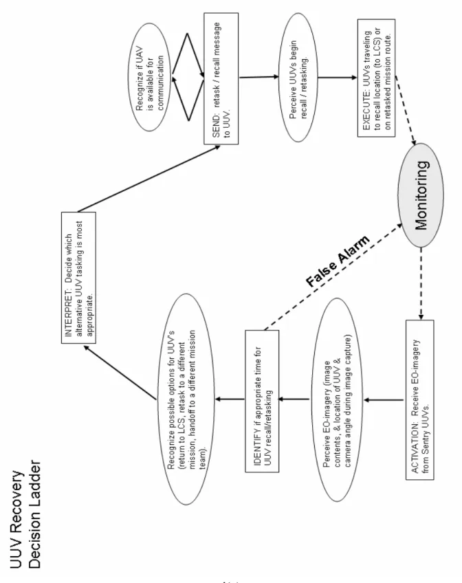
• Figure 4, the UUV Recovery Decision Ladder (D7 from Event Flow), illustrates what
information is nominally needed. Since this phase was not a major focus, the decision
ladder is not as detailed as it could be. This should be a point of focus in Phase II.
3
Table 1. Scenario Task Flow Overview
Mission
Planning
It is assumed that the following issues will be resolved in this phase:
• Search area for Search UUVs will be determined.
• Sentry positions for Sentry UUVs will be determined.
• Mission route for each UUV will be determined.
• Communication / location checkpoints will be scheduled for UUVs.
Helpful information for resolving these issues may include:
• known harbor traffic schedule / peak times • mission clock
• estimated time to harbor entry
• time average target acquisition will take, based on speed of UUVs (transit time), communication time (ATR-flagged EO imagery sent / LCS confirm/reject, new EO imagery acquired, etc.)
• known traffic lanes
• ideal range of UUVs for accurate target ATR
• ideal range of UUVs for accurate target monitoring
• limitations of camera angle view?
• UAV schedule (to include windows of availability for this mission)
Phase Goals
Phase Breakdown
Launch UUVs Phase
- Launch Search UUVs - Launch Sentry UUVs
Mission
Execution
Acquire Target Phase
- LCS tracks progress of UUVs, making sure UUVs are at expected positions at scheduled checkpoints (geo-fix should update actual location)
- LCS tracks status & availability of UAV (ongoing)
- Search UUVs surface to scan shoreline at planned location / time (updated geo-fix position data sent via UAV, if UAV is in range)
- If ATR flags an image during a Search UUV scan, EO imagery is sent to LCS via UAV. If UAV unavailable, UUV loiters, resurfacing & resending at next scheduled checkpoint. Continue until UAV is available. Once EO imagery is sent, UUV loiters until Acknowledgement (Ack) is received from LCS – surfacing at each scheduled checkpoint.
- LCS examines EO-imagery, then sends Ack back to all UUVs. If Ack is ‘positive’, UUV continues to loiter in current position, monitoring confirmed target. If Ack is ‘negative’, UUV resumes search task.
- Acquire phase is complete once one of the UUVs has received a ‘positive’ Ack from the LCS. Second Search UUV should be retasked to confirmed target location for redundant monitoring (or retasked to another potential target or returned to LCS)
Table 1. Scenario Task Flow Overview (cont’d)
Phase Goals
Phase Breakdown
Monitor Target Phase
- Search UUV should continue to surface at scheduled checkpoints to continue monitoring target – ATR should continue to flag target as contact of interest and update imagery.
- When onboard ATR no longer has target in camera range, target tracking should be handed off to UAV…last known location should be available to Sentry UUVs, to UAV’s MTI program, and to LCS.
- When target is lost by Search UUV(s), Sentry UUVs, UAV (if available) & LCS should be given last known location by UUV as well as historical and predicted track of target.
- Monitor Target phase is complete once UAV is tracking the target, or Search UUVs handoff to Sentry UUVs.
- LCS should retask or recall Search UUVs
Tracking Target Phase
- UAV should use last known location from UUV + MTI software to track target. UAV should send LCS MTI feed.
- LCS should monitor LCS MTI feed
- LCS should determine estimated time of arrive of target at harbor entrance based on MTI feed from UAV and schedule Sentry UUVs to surface and capture EO-imagery of expected target location at that time via UAV communication link (this should be automated to the highest degree possible).
- Tracking Target phase is complete once target reaches Sentry UUVs, UAV tracking could be discontinued at this time.
Mission
Execution
(cont’d)
Exit Harbor Phase
- Within a predetermined window of time, Sentry UUVs should surface and wait for target arrival,
- UUV should capture and send collected EO-imagery to LCS via UAV. If UAV is unavailable, surface at scheduled time intervals to retry EO-imagery transmission. Continue cycle until Ack is received from LCS. Regardless of Ack status, at least 1 UUV will track the target out of the harbor based on a set of predetermined criteria.
- LCS should determine tracking profile of Sentry UUVs and determine when they will be retasked or recalled.
Mission
Recovery
Once the Mission Execution Phase is completed - or is aborted - UUVs should be recalled to LCS or retasked to another mission.
5
Table 2. Situation Awareness Requirements for the LCS Operator
Level I (Perception) Level II (Comprehension) Level III (Projection)
- Visual & audible alert when UAV leaves or returns on-station duty (D2)
- Error/alert message clarification (L1, D2, P1, D3)
- All agents’ position information (D3) - Hazardous areas (L1, D2)
- Geo-spatial boundaries (L1, D2)
- Vehicle limitations (on demand) (P1, D3)
- Indicate communications link coverage range when on-station (D2, D3)
- Sensor coverage should be visualized on tactical map (D2, D3)
- UUV schedules (D2, D3)
- Health & status of UUVs (L1, D2)
Acquire Target
Phase - Visual/audio feedback for
confirmation of target acquisition (D2, L1, D3)
- Strength of comms link to UUV scheduled to check in should be indicated on tactical map (based on current position of UAV and comms range) (D2, L1, D3)
- Expected connection should be indicated at UUV scheduled
checkpoint time – if UAV out of range / unavailable, missed connection should be indicated (L1, D2) - Temporal constraints (P1)
- Schedule of estimated UAV on-station availability should be provided on a visual timeline (D2, D3) - Uncertainty of estimated timeframes should be indicated on availability timeline (D2, D3) - Potential missed communications points (D2, D3)
- Future likely UUV tracks (D2, D3)
- Vehicle limitations (when predicted to exceed some safe region) (D3)
- UUV schedules (D2, D3) - Prediction of system
health/status (D2) - UAV MTI imagery (D4, P2)
- UUV target imagery/sensor data (D4, L3, P2)
- MTI exploration capabilities (playback, zooming) (D4, L3, P2)
- Visual & audible alert when UAV leaves or returns on-station duty (D4, L3, P2)
- UAV handoff constraints (P2)
- All agent position information including target (D4, L3, P2)
- Health & status of UUVs (D4, P2)
- Indicate communications link coverage range when on-station (D4, L3, P2)
- Sensor coverage should be visualized on tactical map (L3)
- Comms link coverage should be visualized on tactical map (D4, L3, P2)
- Strength of comms link to UUV scheduled to check in should be indicated on tactical map (based on current position of UAV and comms range (D4, P2)
Tracking Target
Phase
- Visual & audible alert when target is dropped (L3, D5)
- Potential environmental hazards for tracking (L3, P2)
- Feedback if target is dropped (L3, D5) - Expected connection should be
indicated at UUV scheduled
checkpoint time – if UAV out of range / unavailable, missed connection should be indicated (D4, L3, P2)
- Uncertainty of predicted target location should be displayed on tactical map (D4, L3, P2) - Predicted target track (L3, P2) - Schedule of estimated UAV
on-station availability should be provided on a visual timeline (D4, L3, P2) - Uncertainty of estimated
timeframes and position for handoff should be indicated on availability timeline (P2) - Availability schedule should
also indicate the UUVs’ scheduled checkpoint times (D4, L3, P2)
- Vehicle limitations (when predicted to exceed some safe region) (P2)
- Prediction of dropped contact (L3, D5)
7
Table 2. Situation Awareness Requirements for the LCS Operator (cont’d)
Level I (Perception) Level II (Comprehension) Level III (Projection)
- Visual & audible alert when UAV leaves or returns on-station duty (D6, L4, P3, D7)
- Sentry acquisition confirmation (D6)
- Indicate communications link coverage range when on-station (D6, L4, P3, D7)
- Comms link coverage should be visualized on tactical map (D6, L4, D7)
- Strength of comms link to UUV scheduled to check in should be indicated on tactical map (based on current position of UAV and comms range) (D6, L4, D7)
- All agent position information (D6, L4, D7)
- Health & status of UUVs (D6, L4, D7)
Exit Harbor
Phase
- Visual & audible alert when target is dropped (D6, L4, D7)
- Expected connection should be indicated at UUV scheduled
checkpoint time – if UAV out of range / unavailable, missed connection should be indicated (D6, L4, D7)
- Schedule of estimated UAV on-station availability should be provided on a visual timeline (D6, L4, D7) - Uncertainty of estimated timeframes should be indicated on availability timeline (D6, L4, D7) - Availability schedule should
also indicate the UUVs’ scheduled checkpoint times (D6, L4, D7)
- Vehicle limitations (when predicted to exceed some safe region) (D6, L4, P3)