A Combined Radiographic and Time-of-Flight method
for Zero-Knowledge Warhead Verification
by Jake J. Hecla
SUBMITTED TO THE DEPARTMENT OF NUCLEAR SCIENCE AND
ENGINEERING IN PARTIAL FULFILLMENT OF THE REQUIREMENTS FOR THE DEGREE OF BACHELOR OF SCIENCE IN NUCLEAR SCIENCE AND
ENGINEERING AT THE MASSACHUSETTS INSTITIUTE OF TECHNOLOGY
June 2017
Jake Hecla. All rights reserved
Signature of Author:
Signature redacted_____
/
'
Jake Hecla
Signature redacted
Department
of Nuclear Science and Engineering
Certified by:
Areg Danagoulian
Accepted by:
Assistant Professor of Nuclear Science and Engineering
_____________Signature
redacted--ARCHIVES
MASSACUET1S ITUTE OF TECHNJOLOGY_JUL 19 2017
LIBRARIES
Michael Short Assistant Professor of Nuclear Science and Engineering Chairman, NSE Committee for Undergraduate StudentsThe author hereby grants to MIT permission to reproduce and to distribute publicly paper and electronic copies of this thesig document in whole or in part in any medium now known or hereafter created.
77 Massachusetts Avenue Cambridge, MA 02139
MfTLibraries
http://Iibraries.mit.edu/askDISCLAIMER NOTICE
Due to the condition of the original material, there are unavoidable
flaws in this reproduction. We have made every effort possible to
provide you with the best copy available.
Thank you.
Some pages in the original document contain text
that runs off the edge of the page.
A Combined Radiographic and Time-of-Flight method for
Zero-Knowledge Warhead Verification
by Jake J. Hecla
Submitted to the Department of Nuclear Science and Engineering on May 18, 2017, in partial fulfillment of the requirements for the degree of Bachelor of Science in Nuclear Science and
Engineering
Abstract
A novel means of combined spectroscopic and radiographic zero-knowledge warhead verification has been developed and investigated using Monte Carlo simulations. This verification approach, henceforth called "epi-ZK," uses time-structured beams of epithermal neutrons to verify weapon isotopics and geometry without creating or transmitting meaningful information about the device design. This method seeks to remedy information security and hoax resistance issues inherent in previously proposed zero-knowledge verification methods such as fast neutron radiography with preloaded detector arrays and NRF based methods. By using a combination of epithermal neutron radiography and time-of-flight analysis, the epi-ZK method achieves sensitivity to subtle isotopic and geometric hoaxes, while preserving a high level of information security. Results using a MCNP5' model of the verification setup on the "Black Sea Object" pit geometry as well as a speculative HEU implosion weapons design indicate that the method would be highly effective, even using existing research reactor or accelerator neutron sources. This method of verification therefore presents a viable means of verification for weapons previously excluded from treaties such as START due to a lack of information-secure means of assuring device authenticity.
Thesis supervisor: Areg Danagoulian
Title: Assistant Professor of Nuclear Science and Engineering
1 Introduction
1.1
Motivation
Weapons verification describes the process by which two or more parties establish mutual trust that an object claimed to be a weapon matches the description provided by the possessor. The lack of a viable means of verification for individual nuclear weapons has presented an impediment to the limitation of nuclear arms for several decades. Multilateral nuclear disarmament treaties require assurance that all parties are fulfilling their obligations in a manner that does not place any signatory at a strategic disadvantage. This requires a means of weapon system authentication to assure that the dismantlement of weapons systems is taking place per the agreement. However, the direct verification of warheads has never been incorporated into any successful arms control treaty. This is primarily a result of the problem of providing robust verification while protecting classified weapons information which could be useful to a nuclear adversary. Despite three decades of work by scientists worldwide, a viable warhead verification protocol for future arms reduction is not apparent.
Early investigations into the possibility of verification and disposal highlighted the challenges that remain today. Project Cloud Gap, a US Arms Control and Disarmament Agency project2
,
concluded in 1969 that truly verifiable dismantlement of individual weapons was effectively impossible with existing technology, as "many items of classified weapon design information would be revealed even at the lowest level of intrusion." During testing, untrained physicists with minimal knowledge of nuclear weapons design were able to determine a wide variety of classified, militarily useful details about weapons design through little other than examining the exterior of weapons and a few select internal components provided to them after disassembly.
As a result of the glaring security issues present in warhead verification, the issue of direct weapons authentication has been largely avoided in international treaties. The majority of nuclear arms control treaties, such as SORT and New START therefore provide for inspections of delivery systems, rather than the weapons themselves. Assuming that a significant fraction of the signatories' weapons are deployed in such delivery systems, this approach can provide a reasonable means of verifiably limiting a signatory nation's nuclear capability.
Dismantlement of aircraft and missile systems in most cases can be monitored in person or via satellite imagery, and re-manufacturing such objects is commonly acknowledged to be prohibitively expensive. This method therefore presents an effective and politically palatable means of facilitating disarmament which does not risk generating an asymmetry in nuclear capabilities. However, such methods are unusable for non-deployed or otherwise un-mounted nuclear devices. While such weapons were not of primary concern during the Cold War and the immediate aftermath, successful disarmament efforts have resulted in nuclear arsenals that consist primarily of these devices. Current (5/2017) weapons audits performed by NTP show that approximately 13,000 nuclear weapons remain in some form of stockpile, and therefore are immune to the verification and dismantlement efforts aimed at deployed weapons.
Development of a technical means to carry out warhead verification which is robust against hoaxing and does not generate classified information would remove a significant barrier to reducing the number of nuclear weapons by rendering stockpiled and stored weapons vulnerable to verification and dismantlement'. While the number of deployed weapons is of primary concern for military planners, non-deployed weapons are vulnerable to theft, misuse or rapid re-activation in times of crisis. While diplomatic and institutional hurdles to limiting these weapons would of course remain, the development of a technical capability to include non-deployed weapons in arms control negotiations would represent a significant step forward for arms limitation agreements. US-Deployed, 1740 us-Nondeployed, Olher 6,260 nations, 1105
Fig.1: The majority of nuclear weapons are held in military stockpiles or in other "non-deployed" means. These weapons are difficult to bring into arms control negotiations, as they cannot be verified for disposal using existing technical means. Though they are less relevant to the threat of interstate nuclear exchange, they are potentially vulnerable to theft or deployment in times of political crisis.
1.2 Project overview
This project focused on the development of a verification technology which could serve to eliminate the technical barrier to the reduction of nuclear stockpiles by providing a robust means of secure weapon authentication. This thesis includes the design, simulation and evaluation of
' The epi-ZK method described herein requires a trusted template referred to as a "golden warhead" which all subsequent items are compared. Therefore, this method can render non-deployed weapons vulnerable to arms reduction treaties only if a trusted warhead of that type can be identified. Typically, this is based on context (a deployed warhead is likely to be authentic).
this novel zero-knowledge weapons verification system. In contrast to past approaches to weapons verification, this method was designed to not generate or reveal sensitive information about the weapon, and does not suffer from the same information security or hoax resistance issues inherent in previously published zero-knowledge approaches.
The epi-ZK method is effectively a form of neutron radiography combined with time-of-flight (TOF) spectrometry. To validate an object, it is placed in-line with a "reciprocal object" which is designed such as to generate a spatially uniform radiograph and TOF spectrum when added in line with a valid pit. This method was simulated on a speculative HEU pit design using MCNP5/6 in order to verify that it met requirements for information security and hoax resistance.
Simulations show that the radiograph of a valid pit and reciprocal is indistinguishable from that of a uniform plate of the same areal density, which confirms the method preserves geometric information. Likewise, sampling the TOF spectrum inside the radius of the reciprocal object (as projected onto the detector) shows the spectra are identical within error. Simulations were able to conclusively detect a diversion of 10% of the HEU core material (pit density reduced to 17.2g/cc) in a representative weapon design with a source of 33M epithermal neutrons.
2 Background
2.1
Past attempts at warhead verification
Past warhead verification efforts have focused on creating systems which measure classified parameters but conceal the gathered information from the operator. To make such an intrusive measurement palatable to a concerned treaty partner, these devices use an information barrier (software or hardware) to obscure information from the investigating party. In theory, these devices present to the user a judgement on the authenticity of the purported weapon without providing additional information which could compromise the security of the state submitting to verification4.While this claim is technically possible to carry out, developing a mutually-trusted information barrier poses a myriad of issues related to procedures, hardware and software security. As shown by the variety of recent security issues in consumer hardware, backdoors have proven extremely easy to hide, and the accelerating pace of cyber-warfare between the US and potential nuclear adversaries makes any form of mutual trust sufficient to assuage concerns of nuclear theft unlikely5. Based on the threat of classified information leakage, the credibility of the claim that conventional systems can meet the threshold of trustworthiness needed for bilateral disarmament is low.
2.1.1 Attribute verification
Attribute verification seeks to determine whether an object is a nuclear weapon based on the measurement of certain intrinsic characteristics shared by nuclear devices. While each party does not know the technical details of their adversary's weapons, openly-available literature
seems to suggest that any feasible weapons design must include more than -2kg of fissile material in a roughly symmetric, metallic form. Therefore, commonly-proposed attributes include, but are not limited to, plutonium or uranium mass above a threshold, material age, a certain degree of symmetry about an axis and the presence of high explosives. These thresholds must be negotiated by each signatory, and in themselves do not contain classified information. This, in theory, obfuscates the need for an information barrier. In practice most of the devices developed have used them to assuage secrecy concerns'. As in template verification, attribute verification may use either active or passive measurements depending on the statistics required. Attribute systems were developed rapidly in the 1990s to determine the weapons origin of plutonium being stored at the Mayak facility because of perceived insecurities in template systems'.
2.1.2 Template verification
Template verification is a method which seeks to build up a set of measurements which are unique to a certain type of weapon, forming a "fingerprint" against which candidate objects can be compared. These systems notably do not attempt to establish constraints on fissile material mass or other sensitive parameters, and therefore are theoretically more acceptable to a state which is shy about its weapons designs. While this approach could use any array of electrical, mechanical thermal and radiation characteristics, the existing declassified literature indicates that all successful prototypes have relied on gamma-ray counting. The "radiation fingerprint" of a given type of nuclear weapon is unique, as the intensity and shape of various gamma-ray peaks is based on the amount, shape and location of fissile material within the device. In such a system, the largest challenge is ensuring that the template against which treaty-accountable items (TAIs) are compared is in fact valid.
These systems can be further divided into active and passive gamma-ray measurement systems. While passive gamma-ray observations can serve as a source of data for fingerprinting, weapons using heavy tampers or with supergrade pits may not have a sufficiently large gamma signature to be easily verified'. In these cases, an approach using an external neutron source can be used to elicit fission gamma-rays, the number and distribution of which can be used for verification purposes. However, this has the side-effect of revealing the weapon's kf, which can be of use in missile defense.
2.2 Zero-knowledge verification
One approach to solving the security-verifiability paradox is to use a protocol which is able to verify an object's authenticity without creating or transmitting classified data. In computer science, such approaches have existed since the 1980s in the form of "zero-knowledge proofs0." Though the physical implementation of these methods is typically complex, the conceptual design is relatively simple. Zero-knowledge proofs are "interactive proofs" in which two parties (a prover and a verifier) exchange messages to prove a statement, but which demonstrate zero information leakage. That is to say that the performance of the protocol cannot in any way
reduce the verifier's uncertainty about anything other than the statement of which the prover is seeking to convince the verifier. The procedure usually has the following structure":
I. There are two participants, a prover and a verifier. II. The proof consists of a specified number of rounds.
III. In the beginning of the proof both participants get the same input.
IV. In each round, the verifier challenges the prover, and the prover responds to the challenge.
V. Both the verifier and the prover can perform some private computation VI. At the end, the verifier states whether they were convinced or not.
For a concrete example of a near-ZK protocol, envision the following situation: Alice (the prover) wishes to prove to Bob (the verifier) that cups A and B hold the same number of marbles. However, the information regarding the exact number of marbles cannot be disclosed to Bob for security reasons. To show this, she presents Bob with two buckets, both of which she also asserts hold the same number of marbles.
At this point, Alice allows Bob to decide into which bucket each cup of marbles is poured. Once this is done, Bob can then be allowed count the marbles in each bucket. Due to his lack of information on the number of marbles in the buckets, Bob cannot determine the number of marbles added (though he can establish limits on the maximum number added). If Alice was telling the truth, both buckets will have the same number of marbles. If Alice tries to cheat, and loads the buckets unequally, a repeat of the experiment will eventually reveal the deceit. Assuming she does not attempt to cheat, a single measurement is not quite sufficient. The confidence associated with a single measurement is poor (50%), so the game must be repeated until Bob is confident of the results".
0
Alice claims that
two cups contain the same number of marbles
4I41
She then also offers two buckets of marbles She claims these buckets also containan identical number of mables
0
Bob chooses randomly
into which bucket
which cup Is poured
L and (R4or (L and (RL)
0
Bob now counts the marbles in each bucket and should find the same number In both
100 100
50% confidence after 1st game
75% confidence after 2nd game
95% confidence after 5th game
Fig.2: Infographic showing the process by which A=B can be verified without revealing the value of A. Image taken from Glaser et al.
2.2.1 Fast neutron radiography ZK
The general ZK methodology can be easily extended to nuclear weapons verification. Research at Princeton has focused on using neutron radiography for treaty accountable item (TAI) validation". For this method, a fast neutron detector array is preloaded with a negative image of a known valid TAI by party A (the party being verified) using a process which does not reveal the pattern to party B. The TAI is then placed in line with the detector array, and exposed to a fast neutron flux for a given time. The detector pattern resulting from radiographing the TAI combined with the preloaded pattern on the detector plate should be uniform to the level of statistical uncertainty if the known warhead matches the one under inspection. Such an approach has been demonstrated successfully using arrays of neutron-sensitive bubble detectors, and may be generalized to all energy-inneutron-sensitive detectors. Unfortunately, this method is easily hoaxable, as it does not have strong isotopic sensitivity.
U-235 or Pu could easily be swapped with DU without significant consequences to the resulting
image, as the fast neutron total cross sections are similar.
2.2.2 NRF ZK method
Attempts to remedy this issue have been carried out at MIT. This approach (due to Kemp et al.) uses a system which subjects a candidate object to a bremsstrahlung beam. Nuclear resonance fluorescence (NRF) absorption in the warhead creates notches in the transmitted gamma-ray spectrum. The resulting notched beam is then transported through a polymetallic foil, which convolves the notched warhead spectrum with that of the foil material. Rotation and translation of the object can be used to examine the spatial distribution of isotopes, which
vastly increases the hoax-resistance of the technique".This can then be compared to the same dataset from a known real warhead, which should ideally match. While this system is highly hoax-resistant, it may not offer the information security needed for a deployable system".
2.3 Epithermal neutron interrogation
Previously-proposed interrogation methods have relied on fast neutron radiography, gamma-ray emission or neutron emission to characterize nuclear devices. The method proposed herein instead uses epithermal neutrons as an interrogation source. While the generation of such neutrons is difficult, they offer a significant advantage in that actinides have unique, wide resonances in the energy range of 1-100eV. In the epithermal energy range, s-wave nuclear scattering from Z>80 elements is limited, and the dominant contribution to the total cross-section comes from compound scattering in which a neutron briefly attains bound state and is then re-emitted. These resonances offer a powerful means of investigating mixed actinide samples, as they create a one-to-one map between energy-dependent attenuation measurements and isotopic composition.
1 2 3 4 5
energy, eV
6 7 8
Fig. 3: Total neutron cross-section in the range of .1-10eV for three common actinides found in weapons show multiple resonances in the [.1,10eV] range which can be used to uniquely identify various actinides. These resonances are well characterized by the Breit-Wigner distribution and show minimal broadening at temperatures typically encountered in stored weapons. a -nf P1 2000 18001- 1600-1400 [ C C 0 1200 1000 800 600 400 200 U-235 total CS Ptu-239 total CS U-238 total CS
A
010
9 10',' A
.2.3.1 Time of flight neutron spectrometry
For low-energy neutrons such as those used in this study for TAI interrogation, time-of-flight analysis is the only viable means of spectroscopy. Time of flight spectrometry is a technique in which a poly-energetic neutron source is analyzed using the arrival time of neutrons travelling a fixed, known distance. Typically, this is done pulsing the source or by "chopping" a beam into packets using a variable attenuator, then measuring the time of arrival of the neutrons using a detector located at a known distance from the attenuator. Using the Newtonian kinetic energy approximation, the energy of the neutron in each detection event can be easily recovered, and a spectrum can be constructed. For optimal performance in a lab-bench scale experiment, the neutron detector needs to have fairly good time resolution (order of .5us for thermal neutrons). This can be achieved with a gas proportional detector or a variety of fast scintillators with sufficiently fast rise-times".
3 Concept and Protocol
The interrogation system proposed herein consists of an epithermal neutron radiography device which combines imaging and time-of-flight measurements so as to verify both the mass
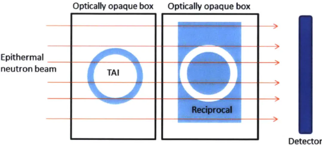
distribution and isotopic makeup of a candidate TAI in a zero-knowledge fashion. This method has been designed with the intent of verifying weapon components (pits, in this case), as they represent the hardest to replicate component of a nuclear weapon. This component evaluation protocol is carried out by placing a candidate object and a "reciprocal object2" in-line with a pulsed epithermal neutron beam. The design of the reciprocal object is such that a valid pit and reciprocal combination present a uniform attenuation radiograph. Likewise, if the isotopic composition and distribution matches, the TOF spectrum of the neutrons traversing the object will match that of a valid item. This method sustains geometric information security by presenting an identical, uniform radiograph for both uniform plates and valid pit objects. Isotopic information security can be preserved by adding uniform layers of various actinides to the reciprocal object. The additional layers allow the possessor to raise the as lower limit on various actinide masses such that they exceed one spherical critical mass of each, which is not useful information to an interrogating party.
2 A reciprocal object is a classified object generated by the possessing party which has the characteristic of possessing a mass distribution which is exactly the inverse of the TAI for a specific axis. When examined with a beam along a specified axis, the addition of the pit and reciprocal results in a uniform image.
Optically opaque box Optically opaque box
Epithermal _____
neutron beam TAI
Reciprocal
Detector
Fig. 4: The verification concept, a basic schematic of which is shown above, employs an object known as a reciprocal which is designed such that the areal-density of a valid pit and
reciprocal is uniform when viewed along rays parallel a certain axis. When radiographed with epithermal neutrons, the resulting detector image is uniform and matches that of a plate of the same areal density. To maintain secrecy, both the pit and the reciprocal should remain at all times in optically-opaque boxes.
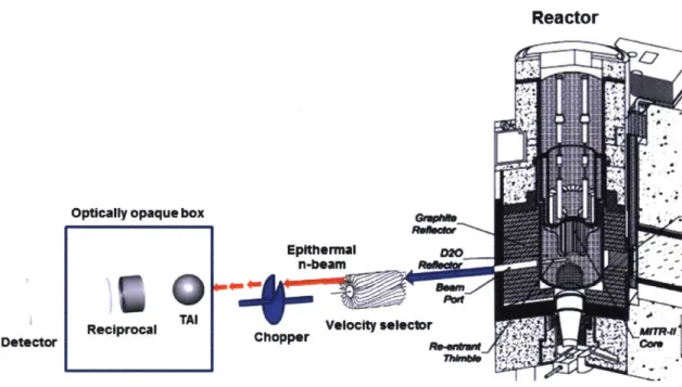
3.1 Epi-ZK device concept and major components
The epi-ZK system shares a strong resemblance to a conventional neutron radiography source with the addition of a velocity-selector (required for broad energy beams) and a chopper. Neutrons in the energy range of [.1,10eV] are selected from a broad-spectrum source such as a reactor or accelerator (employing the p, 7Li reaction or similar) using a velocity selector3. This discriminator may consist of a custom-built finned velocity selector" or a series of choppers designed to only transmit neutrons in a narrow energy range. If the source of energy-restricted epithermal beam is time-continuous, it is then time structured using a variable attenuator. For the purposes of this study, the beam has been assumed to be uniform and unidirectional, which can in reality only be approximated.
The resulting uniform time-structured beam is then transported through the object under investigation and then through the reciprocal. At this point, the original beam of epithermal neutrons has been degraded in intensity by approximately two to three orders of magnitude. The transmitted beam is then be transported down a beamline to allow the beam to spread sufficiently in time for the scintillator, detector and multichannel scaler to resolve individual
3 Alternatively, a pair of synchronized choppers could do the same, but at the cost of a large
beam intensity loss.
neutron interaction events. In order to resolve a feature in the TOF spectrum on a beamline of length L, the open-time of the chopper (topen) must be significantly shorter than the width of the feature in TOF-space. This is described by the condition in which a resonance of FWHM width w (in eV) is centered at Eo:
L Mneut 1 1Eow
topen 2 E0 -w VEO+w
If one wants to achieve an open time/feature width ratio of .10 using a chopper open-time of 900ns18 and a resonance FWHM of .25eV (at 6.9eV, U-238's largest resonance), the beamline would need to be at least 9.1m long. Narrower, higher energy resonances would require even longer beamlines for proper separation. Note that this assumes a detector with zero
uncertainty in arrival time, which is not a valid assumption for most epithermal neutron scintillators.
After the beamline (which may or may not be evacuated), the beam is directed to intercept a large-area pixelated scintillation detector with several hundred individually-coupled readout devices (such as SiPMs) coupled to a scintillator such as LiCaF or Li-glass. It is critical that this scintillator have a high epithermal cross section (Li, B, Gd) and a negligible fast neutron and gamma-ray cross-section (Li, B only). This is due to concerns about information security: fast neutrons and gammas emitted by the pit and reciprocal will have slightly differing arrival times, which would allow an observer to determine some basic pit parameters.
Optically opaque box *10 TAI Reciprocal
Reactor
t r. Ie
EpltherMal Velocity seleclor Chopper iii,0"Fig. 5: This schematic of the verification assembly shows the critical components of the epi-ZK system. The high energy of the neutrons being used in this method necessitates a rather high-velocity chopper based on a turbopump". Likewise, the finned high-velocity selector will require an extremely high rotation rate, and may pose a manufacturing issue, though it may not be needed in an accelerator-based system.
3.2 Necessary and sufficient criteria for warhead verification
For a verification protocol to be viable, it must be both sound and completen. That is, it must able to prove that any true warhead is true (completeness), while rejecting all false warheads (soundness). While a simple computed tomography system would provide such results, the nature of warhead verification does not permit such intrusive inspection. Therefore, a "zero-knowledge" protocol is favored over "information barrier" approaches. A zero-knowledge protocol is defined as an approach that does not confer any sensitive information about the warhead design either directly or through inference by statistical reconstruction.
3.2.1 Defining "zero knowledge" for this application
A zero-knowledge protocol is a form of interactive proof in which two parties (possessor and verifier) exchange messages so as to prove the validity of a statement. These interactive proofs are unique in that they do not exhibit any information leakage. That is, they do not exchange extraneous information beyond the statement which is to be disclosed. For this specific application, however, we can define "useless" information which can be disclosed without endangering the zero-knowledge nature of the system.
In this system, such information includes:
0 An upper limit on pit mass which exceeds one spherical, un-reflected critical mass
* An enrichment or Pu-239/240 ratio uncertainty >25 wt% * The presence of heavy elements (Z>80)
* Neutron multiplication in the TAI/reciprocal
3.2.2 Defining an axiom
Approaching the problem of verification requires that an axiom be developed which connects physical measurements to statements of authenticity. For this work, we adopt a limited axiom only concerning the weapons' core: if the size, shape, isotopic distribution and density of each object within the radius of the high-explosive lenses are identical, the pit is authentic. We exclude the potential of verifying a whole weapon in this paper, as we assume that verification would take place in the disposal process post-disassembly to minimize the exposure of classified information. While the core-only verification axiom is insensitive to details such as the phase of the material, a hoax including fissile material simply in a different phase would be of minimal
utility to the hoaxing party.
For this work, we verify the axiom while fulfilling the requirements imposed by the definition of a zero-knowledge protocol by evaluating the following:
I. Does the radiograph of a valid pit + reciprocal deviate from that of a uniform plate of the same shape and areal density?
II. Does the pixelated TOF spectrum of a valid pit + reciprocal deviate from that of a uniform plate of the same shape and areal density?
III. Does the radiograph of an invalid pit + reciprocal reliably identify all geometrical hoaxes?
IV. Does the pixelated TOF spectrum of an invalid pit + reciprocal reliably identify all isotopic hoaxes?
In practice, the parties involved in verification must establish limits on the deviations from uniformity as well as limits to the fluence which objects could be exposed. While a true ZK method would ideally conceal all relevant information, minor deviations in alignment could reveal details about the weapon if the fluence was allowed to increase without bound. This is equivalent to statement II in 2.2, in which a "game" consists of a finite number of rounds.
3.3 Protocol
3.3.1 Identifying a trusted template and developing a reciprocal
The nature of this zero-knowledge verification protocol requires that at some point that a weapon pit known to be real is used to generate a reciprocal object. While the general implementation of this protocol is outside of the scope of this research a brief outline of this
implementation of "template verification" is presented here based on work by A. Danagoulian2 2:
1. The verifier nation selects a "golden warhead4
" based on its context. This could be plausibly done via a surprise visit to an ICBM site under satellite surveillance. The desire to establish a credible nuclear deterrent makes it overwhelmingly likely that such a deployed weapon would be authentic.
2. The template warhead is transferred to joint-custody and transported to a secure, agreed-upon facility where disassembly can take place.
3. The possessor claims to have completed disassembly, and presents an object in an opaque box which it claims to be the pit of the valid warhead.
4. The possessor presents an object in an opaque box which it claims is a reciprocal object for the valid pit which remains in joint custody.
a. An additional step may be taken to verify that the boxes are emitting radiation using a low-intrusion method such as a NaI(Tl) detector. This is to check that the possessor has not presented a flat plate as a reciprocal and an empty box with no pit.
5. The pit and the reciprocal are aligned on the Epi-ZK device per the
previously-arranged procedure. The ensemble is then exposed to a neutron fluence not exceeding a certain threshold (monitored via TLD) with the full monitoring of both parties.
6. The verifier and the possessor then examine the resulting radiograph and assess if it is uniform within a certain specification. The TOF spectrum is then examined pixel-by-pixel to assure that all paths demonstrate the same TOF spectrum within a certain specification.
7. The reciprocal now remains in joint custody in an opaque container indefinitely. 3.3.2 Examining a TAI
The process by which a treaty accountable item is examined follows the same procedure as steps 5-6 in 3.3.1 (but with a claimed TAI substituted for the known valid pit). In short, a claimed warhead is transported to a facility and transferred into joint custody in such a fashion that its shape is not made apparent to the interrogator. The claimed weapon is then aligned on the epi-ZK beamline along with the appropriate reciprocal generated per steps 1-4. The neutron source is then turned on, and the object reciprocal pair is subjected to a pre-arranged fluence. Once authentication is complete, the weapon is moved to a destruction
, A "golden warhead" is a warhead that is very likely to be authentic and that all subsequent objects are compared to.
facility which alters the fissile material in a mutually agreed upon manner such that remanufacturing the material into a weapon is prohibitive.
4 Methods
The core objective of this project was to use Monte Carlo simulation techniques to determine the viability of the epithermal-TOF warhead verification protocol described in prior sections. As with other evaluations of ZK concepts", four key points are necessary to demonstrate the utility of a given ZK verification method":
I. Isotopic information security (does the method reveal enrichment or quantity of SNM?) II. Isotopic hoax resistance (does the method identify isotopic discrepancies?)
III. Geometry information security (does the method reveal weapon geometry?) IV. Geometry hoax resistance (does the method detect all geometrical discrepancies?)
Testing was carried out by developing MCNP models which would explore each of the four points. The process is illustrated in the following graphic:
1. Select pit dimensions
and materials (1 HEU
design, one Pu design)
NJ
2. Use MATLAB script
to develop reciprocal,
MCNP Input decks
3B. Verify hoax resistance
Hoax TOF spectrum Pit/recip. TOF spectrum
Fig. 6: This graphic shows the major steps of the process by which the hoax resistance and information security of this method were investigated. This process was repeated several times in order to check that the method worked with a range of pit designs/materials.
Additional simulation work was carried out to investigate the design of a realistic detector array. Due to the limited use of epithermal neutrons in research, no commercial, high-resolution imagers exist that are sensitive in this energy range. As a result, a test system would likely rely on a pixelated detector array custom-built at MIT. Such a device would likely consist of an array of 3x3mm or 10xlOmm SiPMs coupled to individual blocks of a scintillator such as Ce:LiCaAlF6 or Li-glass. Though lithium has a poor cross-section in the range of
.1-10eV (6Li has a mean cross section of -100 barns over this interval), it remains the best option. Such a detector was simulated by a tallying the neutron fluence in a 22x22cm array of 1cm pixels 30cm downstream from the reverse of the reciprocal.
17 Nf !1
3A. Verify information security
0
Fig. 7: The blue-outlined 22x22cm radiographic tally plane shown in the image was located 30cm "downstream" from the rear of the reciprocal, and at the same position as the 100x100 radiographic tally plane. The cylindrical volumes shown behind the plane are both voids 10cm in diameter and were used for determining the transmitted neutron TOF/energy spectra.
4.1 Selecting pit designs
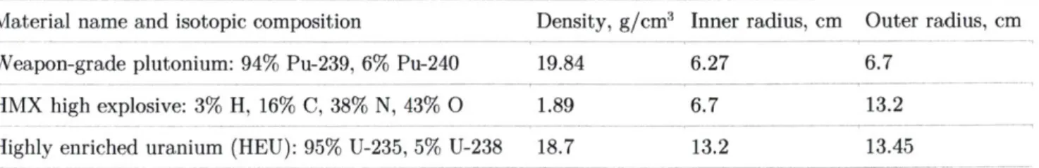
Interrogation using the Epi-ZK method was simulated using MCNP5/6 (a Monte Carlo neutron and photon transport code) using object/reciprocal pair geometries which were representative of several basic weapons geometries. As no declassified information exists as to the construction of modern nuclear warhead pits, the pit designs were based on a publicly-available information which is likely imprecise. The first model consisted of a Pu weapon measured by the NRDC in the 1989 "Black Sea Experiment" in which a SLCM was interrogated using passive detectors. For this work, only the inner Pu layer has been
considered as a valid target of verification because of the layer of low-Z high explosive which is highly neutron opaque. The parameters of the measured core are as follows:
Table 1: "Black Sea Object" composition and geometry. Taken from Kemp (2016). Material name and isotopic composition Density, g/cm3 Inner radius, cm Weapon-grade plutonium: 94% Pu-239, 6% Pu-240 19.84 6.27
HMX high explosive: 3% H, 16% C, 38% N, 43% 0 1.89 6.7 Highly enriched uranium (HEU): 95% U-235, 5% U-238 18.7 13.2
Outer radius, cm 6.7
13.2 13.45
5 Information exists on the geometry of the Trinity device and the Fat Man pit, but it resides in a legal grey-area.
The second design, a HEU spherical implosion device, was based on analysis of weapon case dimensions and simulation work done by Steve Fetter in the process of developing open tools for nonproliferation researchers. While this model has much larger error margins than the geometry of the Black Sea Object, it is nonetheless the best HEU-core model available at the time of this writing.
Table 2: Speculative HEU weapon composition and Material name and isotopic composition
Highly enriched uranium (HEU): 95% U-235, 5% U-238
Beryllium: 100% Be-9
Tungsten: 26.5% W-182,14.3% W-183, 30.6% W-184, 28.4% W-186
HMX high explosive: 3% H, 16% C, 38% N, 43% 0
geometry. Taken from Fetter.
Density, g/cm3 Inner radius, cm Outer
19.84 5.77 7 1.85 7 9 19.3 1.89 9 radius, cm 12 12 22
4.2
Developing a MCNP model
In order to carry out the testing described in 4.1, a MATLAB script was developed to create
MCNP-readable reciprocal geometries. MCNP does not offer the functionality needed to create
surfaces bounded by analytic functions, so the reciprocal models given by the equations below
were divided into cylindrical shells of varying height and radius. These "RCC" macrobody
objects were then arranged to approximate the shape given by:
x=D+2 R y2 --2 R -yzfor |y|
<
R2x
= D + 2R
- y2for
R2 < yj<
R1Where R
2and R
1are the inner and outer radii, respectively, and D is the reciprocal total
thickness.
4.5 4 3.5 3 2.5 1.5-0.5 0 0 2 3 4 5 6 *-dnimrson, c
MATLAB input writer
MCNP5 model
Fig. 8: (Left): 2D cross-section of pit/reciprocal geometry for the Black Sea Object generated using the MATLAB input writer. (Right): 2D rendering of the same geometry (additionally showing the DU plate behind the object/reciprocal combination.
4.3 Application of the Epi-ZK method to a HEU pit design
The MATLAB script described previously was used to develop MCNP neutron transport models of the verification system. For the first set of tests, a 7cm diameter HEU pit geometry was selected. This design was derived from Steve Fetter's work, and is assumed to be representative of a spherical US or Russian HEU burning weapon core. A minimum-thickness reciprocal (7.9cm) was generated for this geometry and placed in-line with the beam located 30cm from the center of the pit (as measured from the flat face of the reciprocal). The interrogation source was modeled as a uniform, parallel beam with a circular cross-section and a flat [.1eV,10eV] neutron energy distribution.
Several distinct MCNP models were developed in order to analyze the validation scheme for information security and hoax resistance. These models included a valid pit/reciprocal combination, a DU (99.7% 'U) pit hoax, a 90% density HEU diversion hoax and a uniform plate. All models other than the uniform plate used the same 8cm diameter reciprocal object with an added 1cm thickness depleted uranium backing plate. For the purposes of this investigation, HEU was defined as consisting of 90% 'U and 10% U without any trace U
isotopes or alloying agents.
Radiographic tallying was conducted using energy-windowed FMESH (F4) tallies located 30cm from the rear face of the reciprocal object. Two tally structures were defined: an 40x40cm array with 10,000 pixels representative of a comnercially-available x-ray imager, and a 22x22cm tally plane with 1cm pixels representative of an epithermal neutron detector which could be made in-house.
All MCNP input files described in this section adhered to the following run specification: MCNP5 (unless otherwise specified)
* ENDF/B VII default cross sections o T = 293K
o No S(a,b) tables
* Material specification from PNNL-15870 (unless otherwise specified) * NPS from 5-80M neutrons depending on the problem
Uniform HEU plate, 150.9 g/cm2
Pit and
reciprocal
Fig. 9: SimpleGeo cutaway plots of the HEU pit geometry and the uniform plate geometry as read from the MCNP input decks. The HEU pit /reciprocal combination and uniform plate geometry both have equal areal density when viewed along any ray parallel to the z-axis (which in this case lies along the line connecting the center of the reciprocal to the center of the pit.
4.4 Application of the Epi-ZK method to a Pu pit design
While the verification of HEU pits is valuable, the vast majority of weapons remaining in US and Russian stockpiles are Pu-burning. To determine the efficacy of the verification protocol on such devices, a pit design based on a Russian SLCM warhead was adopted for a second round of testing. The details of this design, given in table 1, are considered to be representative of a modern nuclear weapon. As in the HEU case, a minimum-thickness reciprocal (5cm) was generated for this geometry and placed in-line with the beam located 30cm from the center of the pit (as measured from the flat face of the reciprocal). The interrogation source was modeled as a uniform, parallel beam with a circular cross-section and a flat [.1eV,10eV] neutron energy distribution.
As in the previously-discussed HEU case, several distinct models were built. These models included a valid WGPu pit/reciprocal combination, RGPu pit hoax and a uniform plate. All models other than the uniform plate used the same 7cm diameter reciprocal object. The pit and reciprocal material was defined per the PNNL material database as DOE 3013 standard WGPu
(93% 2
"Pu, remainder 2
"Pu and trace others). The reactor-grade plutonium was defined as consisting of PWR fuel which had been burned for 33GWd/MTU, resulting in the following composition: 40.8% 239Pu, 30.6% 2"Pu, 14.9% 241Pu, 10.6% 242Pu, 3.1% 23
Pu. As in WGPu, the
density was set at 19.8g/cc.
Radiographic tallying was conducted using energy-windowed FMESH (F4) tallies located 30cm from the rear face of the reciprocal object. Two tally structures were defined: an 40x4Ocm array with 10,000 pixels representative of a commercially-available x-ray imager, and a 22x22cm tally plane with 1cm pixels representative of an epithermal neutron detector which could be made in-house.
All MCNP input files described in this section adhered to the following run specification: * MCNP5 (unless otherwise specified)
* ENDF/B VII default cross sections o T = 293K
o No S(a,b) tables
* Material specification from PNNL-15870 (unless otherwise specified) * NPS from 2-50M neutrons depending on the problem
4.5 Quantifying hoax resistance
Differentiating between a hoax object and a valid TAI requires a set of pre-arranged methods and thresholds radiographic or spectroscopic data is processed. While thresholds are the subject of careful negotiation and therefore cannot be arbitrarily assumed, a variety of plausible metrics for how well a radiograph "matches" another exist. For the purpose of this investigation, a figure of merit for analyzing radiographs was constructed. This figure was defined as the mean of the deviation (in sigma) observed in each radial bin:
i -im ax
FOMGEOM ~ -B1 (i
Where the values Ai and Bi represent the number of neutrons detected in each radial bin for the valid and test geometries, respectively. The total number of channels is represented by Ni.
Likewise, a similar metric was needed to quantify deviation in the time-of-flight spectrum. The level of discrimination was quantified using the isotopic figure of merit defined below.
FOMisotopIc -INA -NBI
NA + NB
Where the values NA and NB are the number of epithermal neutrons detected within the energy
range of [3,6eV] for HEU, and [2,10eV] for Pu. These ranges were selected to optimize the number of resonances covered, providing optimal discrimination. These values were defined as:
6eV
N = NPS * Pi where Pi is the F4 tally value at bin i
3eV
5 Results and discussion: HEU pit
5.1 Geometric information security
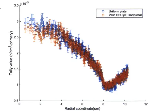
An ideal and completely information-secure radiographic verification method should create identical radiographs for a uniform areal-density object and a valid pit/reciprocal combination. To verify the information security of the method, a test was devised to measure the deviation of the radiograph of a valid pit/reciprocal combination from that of a uniform plate. Two simulations were performed using identical run specifications: one using a valid pit/reciprocal combination and the other a uniform 8cm radius plate of equivalent areal density (150.9g/cm'2). Both patterns used an identical 8cm diameter, uniform intensity beam. In each, the [.1,10eV] epithermal neutron flux was tallied across a surface 30cm downstream of the reciprocal.
The results showed two prominent features: within the radius of the reciprocal, the valid pit and the reciprocal matched very closely (see figure 11). Some small deviations appear to be present at radii under 2cm, but this may be due to sampling issues (the data is recorded in rectangular volumes and plotted in radial volume bins) or simply statistical issues with the simulation. From 2cm to the radius of the reciprocal (8cm), the data sets match within error. However, this does not hold over all space. Near the extremities of the mesh tally (r >2Rrip), there are significant deviations between the plate and the pit/reciprocal data sets due to scattering differences between the two geometries. However, this is of limited concern, as a physical implementation of the protocol would simply limit imaging area to a predefined space.
100 x 4 90 3.5 80 70 3 60-2.5 50-2 40-30- 1.5 201 10 0.5 0 20 40 60 80 100 100 x .4 90-80- 3.5 70-3 60 2.5 50 40 - 2 30 1.5 20 1 10-0.5 0 20 40 80 80 100
Fig 10: Top: A [.1-10eV] radiographic tally of a uniform 150.9g/cm2
HEU plate tallied 30cm
downstream from the reverse of the plate (NPS = 5.0x10⁷). Bottom: Radiograph of a valid pit and reciprocal using the same beam and run specification (NPS=7.9x10⁷
). Note that the far-field image (the area well outside of the radius of the reciprocal) deviates significantly due to the scattering of neutrons by the pit. The information conveyed by this pattern can be removed by
restricting the imaging area to -1.511,, as was done in the realistic detector scheme (see section 7). 3.5 3 2.5 E 2 x10⁻⁵ T L it IL* 1.51. 1 I 0 2 4 T 1I I -1 6 Radial coordinate(cm) 8 10 12
Fig 11: This radial re-binning of the 100x100 FMESH tally shows that the radiograph of the valid pit/reciprocal combination matches exceptionally well with that of the uniform plate. Some small deviations can be observed around 2cm, which is due to the fact that the reciprocal is built of a finite number of shells (-700 in this case), which causes minor deviations from perfect uniformity. The number of particles simulated for was approximately 5.0x10⁷ for the uniform plate and 7.9x10⁷ for the valid HEU pit and reciprocal.
5.2 Isotopic information security
An ideally information secure method would present identical neutron energy spectra at the measurement tally for a uniform plate or a valid pit/reciprocal combination. Two simulations were performed using a valid pit and reciprocal combination and a uniform plate to determine if the energy/TOF spectra generated diverged significantly. The spectra (both energy and TOF) matched within statistical uncertainty.
9'% -f M1
0 0Vald Unifornplate HEU pit +fedpriculI
r
1 0.9 0.8 0.7 1.0.6 0. N 0.5 E 0.4 00.3 0.2 0.1 UnIform plate Vaid pIt +
redprocul--. --- " WN mw 0 0.1 0.2 0.3 0.4 0.5 0.6 0.7 0.8 0.9 1
neutron energy(MeV)
x10-5 x 10⁻⁶ 1.2 1.4 1.6 1.8 2 2.2 2.4Time of arrival, seconds (L=5m)
2.6 2.8 3
x 10'4
Fig. 12: Top: The energy spectra of a uniform plate and a valid pit/reciprocal show almost no deviation from one another. Likewise, the time of flight spectra (bottom) match within error.
9A nf P;1 Uiform plate Vald pkt + reciproAl 7 6 0. 4 N
E
C *2 I 0'
. I I .IThese tallies were carried out in a cylindrical volume located 10cm behind the FMESH tally location with a radius of 10cm.
5.3 Geometric hoax resistance
In order to fulfill the completeness criteria established for the system in section 2.2, the system has to be able to recognize all potential hoaxes. While an exhaustive exploration of such hoaxes is outside the scope of this investigation, two such hoaxes representing "obvious" cases were tested. In the first, a DU pit was substituted for the valid HEU item. A second test was performed with a far subtler hoax, in which 10% of the HEU pit mass was removed by lowering its density. Both hoaxes were easily detected. Using the figure-of-merit defined in 4.5, the DU hoax was detected with a geometrical FOM of 75.9 (based on NPS=6.5x10⁷), while the 10% diversion case gave a FOM of 9.0 (based on NPS=7.9xlO).
The data for the two hoaxes indicate that a 10% diversion hoax would be detectable at a FOM of 5 using 5.9x10⁷ source neutrons, whereas a DU hoax would need only 1.7x10⁷ primary particles.
100.
90
8070
60-50.
40-
30-20
10-0
20
40
60
80
100
100
r-90
80
70
60-50.
40
30
20
100
3.5 32.5
2 1.5 1 0.5 4.5 4 3.5 32.5
2
1.5 I20
40
60
80
100
Fig. 13: Top: The radiograph of a HEU to DU pit hoax. Note the clear outline of the pit (yellow) shown in the radiograph and the order-of-magnitude increase in the average fluence over the valid case (NPS = 6.5x10⁷). Bottom: The radiograph of the 10% diversion case is far more subtle, but the deviation shows up clearly in the radial plot of the data (NPS = 7.9x10⁷).
0 HEU pit + redo ocl
OWNI
I DUpit ho
cd - 1 01 00 2 4 6 Radial coordinate(cm) Fig.14: This radial average tally valueinauthentic object. Only a few tens of object as inauthentic. 4 3.5 R E 2% 12 3 2.5 -:iL L1 .46 2 1.5 -plot of the millions of
HEU-DU hoax obviously identifies it as an
neutrons would be needed to identify this
6
Radial coordinate(cm)
Fig.15: This radial tally that is readily apparent. with a FOM of 5.
of the FMESH tally value for the 10% diversion case shows a difference One would need 5.9x10⁷ [.1,10eV] source neutrons to identify this hoax
90 nf
M
4.5 4 4 3.5-E 2.5 1.5 1 0.51-8 10 12 x 10-5o
Va HEU pit0 HEU pit vit10% dversion1 T I1 0 2 4 8 10 12 ax 2 4 E -aft
0
5.4 Isotopic hoax resistance
Time-of flight analysis used in this verification scheme allows this interrogation system to resolve isotopic differences in hoax objects. As in the geometric hoax resistance test, two potential hoaxes were examined: a DU pit and a 10% diversion pit. Both were easily identifiable.
For the HEU/DU swap case, the FOM was 164.0, while the 10% diversion case had a FOM of 16.0. For the former case, 1.1x10⁷
neutrons would be needed to discriminate at a FOM of 5 (based on NPS=6.5x10⁷
), while the 10% diversion case would require 4.4x10⁷
neutrons (based on NPS=7.9x10⁷). 3 2.51 C) X 10-5 - -UnMfor pute DU hoax 0.1 0.2 0.3 0.4 0.5 0.6 0.7
neutron energy(MeV)
0.8 0.9 1 x10⁻⁵Fig. 16: The energy spectrum of the DU swap at the tally plane clearly identifies the hoax device. Note the large peaks at .18eV and .25eV which are not present in the uniform plate/valid device spectrum
qnf ^;;;1 0
1.4 1.6 1.8 2 2.2 2.4
Time of arrival, seconds (L=5m)
2.6 2.8 3
x 10'4
Fig. 17: The TOF spectrum of the DU swap at the tally plane clearly identifies the However, the distinguishing features in this spectrum are those at low energy (TOF they are easier to resolve as a consequence of the larger time-of-arrival spread.
x10
50.1 0.2 0.3 0.4 0.5 0.6 0.7 0.8 0.9 1
neutron energy(MeV)
x10-Fig.18: The energy spectrum of the 10% pit mass diversion case is subtler than the DU diversion, though it conclusively identifies the fake at a FOM of 5 after 4.4x10⁷ neutrons.
'11 nf M x10-5 1.8 1.6 I F I -Unifbrm plate DU hoax pit
-T
i~
-2~.L
p1.4~1.2
NE
-0.8
0.6
0.4 0.2 ft 1.2 hoax device. > 2E-4s), as I 0.9 0.8 0.7 0.6 0.5 g 0.3 0.2 0.10
Uniform plate10% HEU diversn hoax
x 10-6
~10%
diversion HEU pit + recipromai7 6 ('35
E
04 CLE
3 d) 6 2 0 1.4 1.6 1.8 2 2.2 2.4Time of arrival, seconds (L=5m)
2.6 2.8 3
x104
Fig. 19: The TOF spectrum of the 10% diversion case is strongly suggestive of a hoax, but is not entirely conclusive. This is largely due to the fact that the transformation to TOF space compresses the high-energy features and therefore limits their contribution to the totals used in the FOM figure.
5.5 Criticality
Though a monolithic reciprocal was anticipated to be subcritical for this design, A MCNP6 KCODE simulation was performed in order to ensure that the pit/reciprocal combination did not pose a criticality issue. Beyond the safety concern associated with high k-values, the simulation runtimes become intractable as neutron multiplication creates additional particles to track. Both a uniform plate and the pit + reciprocal design resulted in kff < .90, which posed only a minor runtime increase.
'49 nf 1
0'
6 Results and discussion: Pu
6.1 Geometric information security
As in the prior HEU example, the geometric information security of the approach was tested by comparing the radiograph of a valid pit/reciprocal combination with one produced by an equal areal-density plate. As in the HEU case, small deviations were observed at small radii (~1cm), as well as at very large radii (greater than twice the radius of the pit). The deviation at small radii is again likely due to statistical issues, as only a limited number of particles could be run in the time allotted. The deviations at large radii are likely due to the differing scattering properties of the two systems. Any information contained in the scattering pattern can be removed by limiting the imaging area to a region only slightly larger than the radius of the reciprocal.
100
r
90
80
70
60
50
4030
20 -100
20
40
60
80
100
100
,
90
-
80-
70-
60-50
40-30
20
100
6
5
4
3 2 10
-10~5 8 176
5
4
3
2
120
40
60
80
100
Fig. 20: Top: The radiograph of a uniform plate shows very minor variations from the valid pit and reciprocal combination (bottom). Note that the valid pit/reciprocal combination was the result of about an order of magnitude more primaries than the uniform plate, and therefore the radiographic image quality is significantly higher.
0 UnIm plate 0 Vald pt + repocal
i
2 4 6 8Radial coordinate(cm)
10 12Fig 21: This radial re-binning of the 100x100 FMESH tally shows that the radiograph of the valid pit/reciprocal combination matches exceptionally well with that of the uniform plate.
% ; n-f r; 2.5 * 10-3
2
1.5 -NE
C-, C I-10.51-0
6.2 Isotopic information security
The transmitted neutron spectra for the valid WGPu pit and the uniform WGPu tallied and compared. In a truly information secure method, both energy spectra identical. As anticipated, the spectra matched within error.
2 X 10⁴
Uriform WGPu plate
Vald WGPu pit + reciprocal
I.
I-0.1 0.2 0.3 0.4 0.5 0.6 0.7
neutron energy(MeV)
0.8
0.9
1
X 10-5
Fig.22: The spectrum from the WGPu plate and the valid pit/reciprocal combination match within error, indicating no leakage of isotopic information.
6.3 Geometric hoax resistance
In order to fulfill the completeness criteria established for the system in section 2.2, the system has to be able to recognize all potential hoaxes independent of core material. In the case of a HEU weapon, the most concerning diversion would be a swap of low-grade RGPu for WGPu in a pit, as RGPu is easily obtained in comparison to WGPu. Two simulations (one RGPu, one valid pit) showed that the RGPu hoax is readily apparent (FOM=74.4, NPS = 2.1x10⁷).
'Inj nf !i plate were should be 1.8 1.6
1.4
1.2E
C,5..0.8
0.4 0.2 0L0
100
90-80
70
60-
50-40-30
20
10
0
100 r
90
80
70
60
50
40
30
20
10
20
40
60
80
100
0
20
40
60
80
100
Fig. 22: Top: The RGPu hoax clearly shows up as a radial deviation between ~6.2-6.8cm. Though the coloration in the two plots is the same, each has a differing colorbar scale. The total fluence over the reciprocal region is around a factor of four lower in the RGPu pit hoax case
10
![Fig. 3: Total neutron cross-section in the range of .1-10eV for three common actinides found in weapons show multiple resonances in the [.1,10eV] range which can be used to uniquely identify various actinides](https://thumb-eu.123doks.com/thumbv2/123doknet/14378012.505410/10.917.160.705.530.963/neutron-section-actinides-multiple-resonances-uniquely-identify-actinides.webp)
![Fig 10: Top: A [.1-10eV] radiographic tally of a uniform 150.9g/cm 2 HEU plate tallied 30cm downstream from the reverse of the plate (NPS = 5.0x10 7 )](https://thumb-eu.123doks.com/thumbv2/123doknet/14378012.505410/25.917.139.734.123.975/radiographic-tally-uniform-plate-tallied-downstream-reverse-plate.webp)