Publisher’s version / Version de l'éditeur:
Vous avez des questions? Nous pouvons vous aider. Pour communiquer directement avec un auteur, consultez la première page de la revue dans laquelle son article a été publié afin de trouver ses coordonnées. Si vous n’arrivez pas à les repérer, communiquez avec nous à PublicationsArchive-ArchivesPublications@nrc-cnrc.gc.ca.
Questions? Contact the NRC Publications Archive team at
PublicationsArchive-ArchivesPublications@nrc-cnrc.gc.ca. If you wish to email the authors directly, please see the first page of the publication for their contact information.
https://publications-cnrc.canada.ca/fra/droits
L’accès à ce site Web et l’utilisation de son contenu sont assujettis aux conditions présentées dans le site LISEZ CES CONDITIONS ATTENTIVEMENT AVANT D’UTILISER CE SITE WEB.
Journal of Materials Science, 23, 12, pp. 4415-4428, 1988
READ THESE TERMS AND CONDITIONS CAREFULLY BEFORE USING THIS WEBSITE. https://nrc-publications.canada.ca/eng/copyright
NRC Publications Archive Record / Notice des Archives des publications du CNRC :
https://nrc-publications.canada.ca/eng/view/object/?id=5a084a6d-559d-4073-ba8d-6503ee63eafc https://publications-cnrc.canada.ca/fra/voir/objet/?id=5a084a6d-559d-4073-ba8d-6503ee63eafc
NRC Publications Archive
Archives des publications du CNRC
This publication could be one of several versions: author’s original, accepted manuscript or the publisher’s version. / La version de cette publication peut être l’une des suivantes : la version prépublication de l’auteur, la version acceptée du manuscrit ou la version de l’éditeur.
Access and use of this website and the material on it are subject to the Terms and Conditions set forth at
Crack-enhanced creep in polycrystalline material: strain- rate sensitive
strength and deformation of ice
National Research
Conseil natronal
I*(
Cwndl Canada
de
nclmches Canada
S e r
TH1
Institute for
lnstitut de
Research in
recherche en
N2
laConstruction
no.
1581
construction
c. 2'
BLDG
4 - -Crack-Enhanced Creep in Polycrystalline
Material: Strain-Rate Sensitive Strength
and Deformation of Ice
by N.K. Sinha
ANALYZED
Reprinted from
Journal of Materials Science
Vol. 23, No. 12, 1988
p. 4415-4428
(I RC Paper No. 1581
)NRCC 301 46
N R C-
ClSTYI
R
C
LIBRARY
I
I
BIBLIOTHEQUE
I R C
C N R C-
1CETL'auteur prksente une dquation de fluage viscdlastique non linkaire de matkriau
polycristallin. Celle-ci tient compte de l'effet de la fissuration et peut servir h d-e
les
comportements primaire, secondaire et tertiaire.
Le
modble prdvoit la formation de
microfissures et, par condquent, 1'Ctat d'endommagement dfi au processus de fiagdisation
du pourtour des grains aux temperatures BlevCes.
On
dkrit ici l'utilisation de ce modkle
pour la formulation du fluage accentue par la fissuration et
de
la r m n s e matdrielle dans des
conditions de chargement
B
vitesse de deformation constante (en thkorie le cas le plus
simple mais en pratique le plus difficile
B
cerner). La formulation permet de ddfmir l'effet
de la vitesse sur la rkponse aux contraintes-ddformation et la sensibilitd
B
la vitesse de la
rksistance, du temps de rupture, de la deformation h la rupture, des dommages et de la
vitesse d'endommagement, de la rkcupkration aprbs dkformation, etc. On a observk une
correspondance numdrique entre la thhrie et l'expkrience lors de la comparaison des
prkvisions avec les donnkes, obtenues par fonctionnement en boucle fermke, concernant la
dsistance et la dkformation de la glace pure h vitesse
.
. de
--
&formation constante. Les calculs
ont
Ctk
effectuks
B
l'-:-'-
'--
- - - - -'5s h partir d'essais
J O U R N A L O F M A T E R I A L S S C I E N C E 2 3 ( 1 9 8 8 ) 4 4 1 5 - 4 4 2 8
Crack-enhanced creep in polycrystalline
material: strain-rate sensitive strength and
deformation of ice
N I R M A L K . S l N H A
Institute for Research in Construction, National Research Council of Canada, Ottawa K I A ORC, Canada
A non-linear viscoelastic creep equation for polycrystalline material is presented. It incor- porates the effect of cracking and is capable of describing primary, secondary and tertiary behaviour. The model predicts the formation of microcracks and thus the damage state due to the high-temperature grain-boundary embrittlement process. This paper describes its applica- tion in formulating crack-enhanced creep and material response under constant strain-rate loading conditions (theoretically the simplest case but actually the most difficult to maintain). The formulation makes it possible to define the rate effect on stress-strain response and the rate sensitivity of strength, failure time, failure strain, damage and damage rate, strain recovery, etc. Numerical correspondence between theory and experiment was observed when predic- tions were compared with available closed-loop, controlled, constant strain-rate strength and deformation data on pure ice. Calculations made use of material constants determined from independent constant-load creep tests.
1. Introduction
The mechanical response of polycrystalline ice [l, 21, for example the dependence of strength on strain rate, the dependence of failure time on load and the near constancy in failure strain, is very similar, phenom- enologically, to the mechanical response of polycrys- talline materials in general [3-71. Ice is one of the strongest materials in terms of working temperature, T , expressed as homologous temperature, TIT,, where Tm is the melting point and both T and T, are in the absolute scale (Kelvin). Several physical and microstructural characteristics influence its strength. Low lattice (and grain-boundary) diffusivity, leading to relatively slower matrix relaxation, and larger grains (usually > 1 mm), leading to slower grain- boundary diffusion, are primarily responsible [8].
At the same homologous temperature the rate of diffusion in ice is two or three orders of magnitude lower than that of most other polycrystalline materials [9]. A direct consequence of this phenomenon is a propensity for cracking activity. Grain-boundary embrittlement processes play a dominant role in deter- mining strength and deformation in ice. For this reason and in spite of its rate-controlling effect, intragranular plasticity contributes less to the total deformation at failure in ice than it does in many other materials at stress levels (o > 1 x E, where E is Young's modulus) and strain rates
(t
> 1 x lop7 sec-I) of practical interest in most engineering situations. In conjunction with its optical transparency, this makes pure ice an ideal material for studies of micromechan- ics and, thereby, high-temperature material science.The present paper describes how a high-temperature
rheological model with grain-size dependent transient creep [lo] can be used, with the introduction of crack enhancement of creep, for predicting strength and stress-strain behaviour under constant strain-rate loading conditions. The theory is tested with data on ice. The model permits commonly observed phenom- ena and empirically developed equations to be des- cribed quantitatively.
2. Preliminary analysis
Consider the test results in Fig. 1 for pure S-2 ice: optically transparent, bubble-free, transversely iso- tropic, columnar-grained. At - 10 f O.l°C and under a closed-loop controlled constant compressive strain rate of 3 x lo-' sec-I, a maximum stress of 4.6 MN m-2 was reached. Essentially, this test was conducted following the method described by Sinha [2], although a larger controlling gauge length of 200 mm and an improved technique for mounting the gauge on the specimen was used [ll]. The load was removed quickly (in % 0.1 sec) soon after the maxi- mum or upper yield failure stress was reached. Strain recovery history shows an instantaneous elastic strain,
E, (measured after full unloading, % 0.1 sec), followed by a delayed elastic recovery, E,, and a permanent or viscous strain, E,. Thus the axial strain, E , can be described phenomenologically as
In this case the total strain at the point of unloading consisted of about 23% elastic strain, 28% delayed- elastic strain, and 49% viscous or permanent strain. Elastic as well as delayed-elastic strain play important
Figure 1 Stress and strain histories for columnar-grained S-2 ice, average grain diameter of 5.0mm at - 10°C (0.96Tm) under closed-loop controlled constant strain rate of 3 x sec-I.
TIME, t (sec)
roles in determining total strain. Theoretical develop- ment must therefore consider all the mechanisms res- ponsible for the various strain components. Most analyses in the literature on polycrystalline materials have in general been based primarily on a steady-state (often called plastic) flow mechanism.
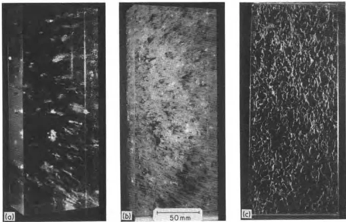
Fig. 2 shows the above-mentioned specimen after testing and another tested at a lower strain rate
(4 x l o p 6 secp'). The second specimen was unloaded soon after reaching its maximum load of 2.4 MN m 2 . The significant differences in the crack densities of the two specimens as well as several early examples [l, 21 make it clear that cracking activity is highly rate- sensitive.
The cracks were long and narrow and parallel to the length of the columnar grains (Figs 2a and b). Fig. 2c
Figure 2 Specimens (50mm x lOOmm x 250mm) after testing at - 10°C under strain rate of (a) 4 x 10⁻⁶sec-' and (b) 3 x 10-~sec-'
shows that the plane of the cracks tends to be parallel to the axis of the imposed compressive stress. Similar observations under constant load test have been reported by Gold [12, 131 for columnar-grained ice and by Cole [14] for isotropic granular ice. Fig. 2c shows that the cracks tend to propagate along grain boundaries oriented within 20" of the axis of the applied load. More inclined grain boundaries are cracked at high strain rates (Figs 3 and 4) during later deformation when the crack density is higher, or around shear planes in compression tests in which the wedging action of the grains leads to triaxial stress states. Similar observations have been made for metals and alloys [15, 161, for example, on stainless steel of Types 304 and 316 [17, 181. In metals and ceramics, for which tests are usually performed in tension, cracks tend to propagate along grain bound- aries oriented normal to the axis of the applied tensile stress.
These cracks are known as wedge-type cracks. It is not a simple matter to separate a wedge-type crack from an opening created by the coalescence of small rounded cavities, as emphasized 30 years ago by McLean [19]. The development of large voids affects the deformation processes in a significant manner [20]. Analysis of strength and deformation must therefore include cracking activity and rate dependence.
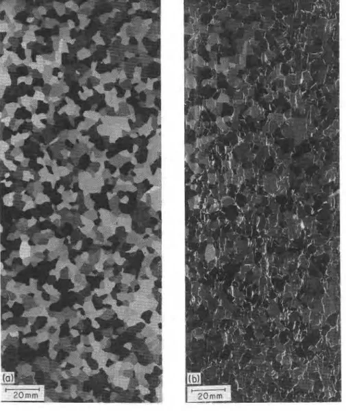
Figure 3 A 0.8 mm double-micro- tomed thin section, made from thick section of Fig. 2c, under (a) cross-polarized light, (b) com- bined polarized light and scattered light, exhibiting predominantly grain-boundary cracks.
3. Microcracking mechanisms
Microcracks, comparable in size to a grain facet, seem to occur under a constant-load creep condition where stress exceeds a critical value (> l o p 5 E, where E is Young's modulus) commonly known as the Stroh- McLean transition. Stroh [21] described this minimum stress in terms of the length of a sliding interface, the surface-free energy and the shear modulus. McLean [22] used Stroh's relation for grain-boundary cracking by identifying the interface with the grain boundary and surface energy with the effective fracture surface energy. Sinha [23] has shown the general applicability of the Stroh-McLean equation to polycrystalline ice. Calculations confirm that the predicted minimum stress is about twice the value actually observed [12, 241. It has been pointed out, however, that this classical treatment as well as that proposed by Smith and Barnby [25] do not give any information on the stress- and temperature-dependent incubation time usually required under moderate stress ( > E) before the initiation of cracks and the significant dependence of cracking activity with further loading.
By invoking Williams' [26] treatment of Cottrell's equation [27] for the stability of a void formed by dislocations on two intersecting planes, and by replac- ing the wedge height with grain-boundary displace- ment, Sinha [23] showed that a critical grain-boundary
sliding (g.b.s.) displacement, and hence a critical grain- boundary sliding strain, might be required for a void at the interface to grow in an unstable manner that leads to a wedge-type crack.
3.1. Critical g.b.s. displacement for crack initiation
The hypothesis of a critical g.b.s. displacement, Z,, for the formation of cracks comparable in size to a grain facet was initially applied to observations of polycrys- talline ice [28]. Detailed studies [23,28] showed that 2,
in the limited uniaxial stress range of 5 x 10P5E to 2 x l o P 4 E and temperature range of 0.88Tm to 0.98Tm in previously undeformed clear ice depends only on temperature. Thus
dl
2, = (M, - m, T )
2
= (MI - m, T ) (2) where dl is the unit dimension (= 1 m); M I , m, are constants, and K (assumed to be unity) is another constant arising from Gifkins' [15] equation of pro- portionality between g.b.s. strain, , &,,, and average g.b.s. displacement, 2,where d is the average grain diameter expressed in units of dl (m).
Equation 2 is qualitatively supported by direct experimental observations in other materials. The dependence of cavity formation on the amount of grain-boundary sliding was reported by Intrater and Machlin [29] in copper bicrystals, and similar observa- tions have been reported by Fleck et al. [30] in a
copper alloy. Experimental support for a critical grain-boundary sliding displacement for crack initi- ation has been provided by Watanabe [31] on copper bicrystals and Morris and Harries [I81 in steel.
The key hypothesis in the development of Equation 2 is that delayed elastic strain, E,, is associated with a grain-boundary sliding mechanism [lo] given, as a first approximation, by
Equations 2 and 4 give the critical delayed elastic strain for the onset of cracking activity as
3.2. Onset of creep cracking
Equation 2 proved to be useful in predicting the stress and temperature dependence of time, t,, for the onset of cracking activity in polycrystalline materials [23]:
where
x
= K2,/cld, is a constant at a constant tem-perature and t, is the temperature-dependent grain-
boundary relaxation time, having the same activation energy as that of matrix deformation; c,, s and b are material constants. The constant s is the stress exponent for grain-boundary sliding [lo], and b is the time exponent for transient, or strictly speaking, delayed elastic strain [32].
The value for s may be between 1 and 4 for poly- crystalline materials. The initial rate of sliding has been found to be linear (s = 1) for both copper [33] and tin [34]. Strutt et al. [35] found a value of s = 2.8 for lead bicrystals, and Langdon [36] found one of
w 2.4 for aluminium and magnesium alloy.'A value of 4.7 for a low-carbon steel and of 3.8 for 316 stainless steel was reported by Horton [37]. Gates [38] also found a value of 3.8 for 316 stainless steel. For ice, however, there are no experimental data on grain- boundary sliding. The assumption given in Equation 4 and experimental observations on creep [32] led Sinha [lo] to conclude that s w 1 for ice (see Table I). Since Andrade's proposal in 1910, little attention has been paid to transient creep in metals and alloys. Very little is known about delayed elasticity in general, although phenomenological time-hardening and strain- hardening equations have been proposed [3]. Shear or sliding in the grain-boundary regions during loading, originally suggested by Zener [40], was hypothesized by Sinha €101 as the primary micromechanism that gives rise to a delayed elastic effect in a polycrystalline material. This idea, together with the additional hypothesis discussed in Equation 4 and the assump- tion that intragranular dislocation creep is indepen- dent of grain size, led to modification of the phenom- enological equation proposed for transient creep [32] and the introduction of a hybrid solution that intro- duces a grain size effect [lo],
where t is time and a , = l/t;; other symbols have been defined earlier.
Equations 8 and 4 give the stress-time-temperature dependence of Z,
T A B L E I Material constants for creep and cracks for pure ice obtained from earlier creep experiments and analyses
Ref. Constant [321 E = 9.5GNm-' c , = 9 x d, = I m (chosen unit) n = 3 b = 0.34 % I/n a , = I/T, = 2.5 x 10⁻⁴sec-1 (T = 263 K) iv0 = 1.76 x lO-'sec~' (T = 263 K, u, = 1 MNm-') [lo1 K = l s = l [23] MI = 1.67 x m , = 4.55 x 10⁻⁹K-' [39] N , = 550m-' = 1.33 x 10'11-I
Equations 8 and 9 clarify the significance of s and b used earlier, but there appears to be no available information on the values of b for other materials. Sinha [ l o ] found that b z lln for polycrystalline ice where n is the stress exponent used in power-law expressions for the viscous flow rate, often incorrectly referred to as the steady-state or minimum creep rate. The exponent n is associated with an intragranular dislocation mechanism without any influence from cracks. Whether this simplification ( b z Iln) can be extended to other materials remains to be seen.
For ice, Equation 7 simplifies to
which provides a t,-a relation very similar to the stress dependence of rupture life, commonly observed, and fitted by essentially empirical equations [41,42]. It is micromechanically based and has been shown to be better [23] than the well-known Zhurkov [43] equation used by Gold [12, 441 for ice and for describing the dependence of tensile rupture time on stress for metals and alloys [45]. In addition, Equation 10 does not suffer from the impossibility that Zhurkov's equation predicts, i.e. a finite rupture time even for vanishing small stress. This incongruity emphasizes the empiri- cal characteristics of the Zhurkov equation, although efforts have been made to describe it as a kinetic theory of fracture [46].
3.3. Minimum stress for creep cracking
Substitution oft, = coin Equation 6 and rearrange- ment gives the minimum stress, a,,, for the onset of cracking activity,
Usually E decreases with increase in temperature. Equation 2 shows that 2 , also decreases with increase I
in temperature. Thus Equation 1 1 shows that a,, is a decreasing function of temperature and provides results
[23] that agree extremely well with the experimental observations of Gold [12] and Zaretsky et al. [24].
3.4. Creep damage
When the applied stress is greater than omin and the load duration is greater than t,, then with continued deformation more and more sites of stress concentra- tion reach a critical point and the number of cracks increases. This continued damage mechanism has been investigated by Sinha [39], who noted that Gold's available experimental observations [12, 131 on the stress and time dependence of crack density, N , in ice can be expressed as a function of grain-boundary sliding displacement. The simplest equation would be of the form
N = N, exp [$ ( 2 - :,)I (12)
where 2 is given by Equation 9 and 2 , by Equation 2.
Nc is the crack density corresponding to 2 , on first cracks, and $ is a constant. A better presentation of Equation 12 would be
N = N c { e x p [ $ ( 2 - ? , ) I - 1 ) (13)
This avoids the problem inherent in Equation 12, i.e. that the crack density, even at the beginning of the test, has a positive, though very small, value. Equation 13 also shows that cracks form at t,, when 2 = 2 , .
Equation 13, on the other hand, predicts that the crack density is "negative" for 2 < 2 , . This absurd condition can be avoided mathematically by recogniz- ing that a negative value for N is equivalent to no cracks.
An explicit form of N in terms of delayed elasticity or stress and time is given by inserting 2 from Equation 4 in Equation 13, giving
With Equation 8 this gives
N = N. (exp {$
[+
('J
{ I - exp [ - ( ~ , t ) ~ ] }4. Creep without damage
For stresses less than a ,,,, that is a < a
,,,,
the three terms in Equation 1 for constant-stress loading can be described as [ l o ]( 1 - exp [ - ( a T t ) * ] )
where the second term ( E , ) is described by Equation 8 and the third term ( E , ) represents the usual power-law viscous creep; thus iV, is the viscous strain rate corre- sponding to the chosen unit of stress, a,, (= 1 MN mp2).
The recovery curve is given by the mirror image of E,.
5.
Creep w i t h damageFor a < amin and t > 0 or for a > a,, and t < t,, Equation 16 is applicable, but for loading conditions, a > omin and t > t,, the deformation behaviour is continually modified by the increasing number of microcracks that develop during loading. These affect elastic as well as other components of strain.
5.1. Elastic creep
Because of internal stress concentrations, the nuclea- tion and growth of cracks or cavities induce additional elastic strain, leading to elastic creep or time-dependent elastic modulus. Venkateswaran and Hasselman [47] concluded, however, that the total strain of elastic creep by crack growth is of the order of a small multiple ( 2 to 3 ) of the initial elastic strain to which the material is subjected during initial loading. This point is supported by data compiled by Miller and Langdon
[48], suggesting that for many metals the total cavity volume fraction rarely exceeds 1 %. Although elastic creep contributes little to the total strain, this mechan- ism should be given consideration if the cavity volume fraction is large or if elastic strain contributes signifi- cantly to total strain.
Crack-enhanced elastic creep can be estimated readily enough from experimental recovery curves (Fig. 1). The instantaneously recovered strain of 4.5 x lop4, in this case corresponding to a stress of 3.5 M N m p 2 at the time of unloading, provided an effective Young's modulus value of 7.8 MN m-'. This is about 18% lower than the value for Young's modulus, E, of 9.5MNm-2 determined for an uncracked specimen 1321 and given in Table I. Elastic creep strain in excess of the initial elastic strain therefore contributed only about 4% to the total strain in spite of the extensive damage shown in Fig. 2. Unless the deformation is extended to large strains or strain rates, it would be simpler to neglect the effect of elastic creep. The same applies to delayed elastic strain. This point will be discussed later.
5.2. Crack-enhanced viscous creep
Considering a crack as an array of dislocations, Weertman [49] derived the effect of cracks on viscous creep rate. For dilute concentrations of non-interact- ing long narrow cracks oriented with their major planes perpendicular to a uniaxially applied tensile load, and for materials obeying a power-law viscous creep rate such as the third term in Equation 16, the enhanced creep rate,
Eve,
is given byi, = 1, (1
+
27cN~'n'~~) (17) where Ev is the creep rate for material without cracks and N is the number of cracks per unit area. All the cracks are of uniform size, and 2a is the crack width. Here N indicates the number of cracks that cross a unit cross-sectional area oriented perpendicular to the plane of the cracks. The condition for non-interaction of cracks is defined by aZ N @ 1.Adopting Equation 17, the non-linear viscous strain under constant-stress creep conditions, involving cracking, is given by
Since N = N(o, t) at constant temperature, it is impossible to use Equation 18 without knowledge of the dependence of N on stress and time. This explains, perhaps, why Weertman's theoretical development has never, to the author's knowledge, been used in the quantitative analysis of creep problems involving cracks, although it has been discussed by Hasselman and Venkateswaran [50] for qualitative descriptions of the effects of cracks on creep in polycrystalline ceramics.
Equation 18, with its underlying theoretical assump- tions and limitations, is particularly applicable to the type of damage that occurs in unidirectionally solidi- fied columnar-grained solids such as those discussed earlier (Figs 1 and 2). It can readily be applied because N is described by Equation 15. Some assumptions must of course be made as to the size, 2a, of the cracks. If the cracks are assumed to be the same size as those of the grain facets, as suggested by Fig. 3b and Fig. 4, and if the cross-sectional geometry normal to the lengths of the grains is assumed to be hexagonal, then 2a can be expressed in terms of the grain
diameter, d. Assuming the area of a hexagon of sides 2a to be equal to the area of a circle of diameter d, it can be shown that
or that crack sizes are about half the grain diameters (i.e. 2a % 0.55d).
Substitution of a2 from Equation 19 in Equation 18 gives
Viscous strain involving cracking therefore depends not only on N, which depends on o and t at a constant temperature, but also on grain size.
5.3. Constitutive equation
Replacing the third term in Equation 16 by Equation 20 and neglecting elastic creep, the rheological equation is obtained:
( 1 - exp [ - ( ~ , t ) ~ ] )
(21) where N is from the second (delayed elastic) term through Equations 14 or 15 and a Z N 4 1 or . n d 2 ~ / 24 x 3'12
<
1.Equation 21 reduces to Equation 16 for any stress and t < t, or for any time and o < o , , . In the first case, the creep period would be in the transient range I
(often called primary creep) and the second term could dominate the deformation process, resulting in a pro- nounced grain size effect. In the second case, the grain- size dependent creep curve would eventually lead to a constant strain rate (often called a steady state) that does not depend on grain size. For conditions o >
a,,,, involving cracks, the creep curve would pass through a minimum creep rate to an accelerating creep rate known as the tertiary state. Thus Equation 21 describes the complete creep curves normally observed (further implications will be discussed in another paper). Its application in predicting stress-strain, and hence strength, response for constant strain-rate tests will be developed because (i) it is theoretically the simplest case, (ii) it is challenging, and (iii) experi- mental data have become available through the use of the new generation of closed-loop strain-controlled test machines.
6. Constant strain rate
A theory for predicting strain response and hence stress-strain diagrams for non-linear materials at various temperatures corresponding to monotonically increasing stress histories has already been developed [51]. It is based on Equation 16 and consequently is applicable strictly for conditions in which no crack- ing activity is involved. Although good agreement between theory and experiment was obtained even for
conditions of a fair degree of cracking, the theory should not be extrapolated far beyond its range of application. The analysis provided, however, a basis for applying a constant-stress creep equation to a variable- stress loading condition. It also provided support for the two basic assumptions used at constant tempera- ture: (i) that the delayed-elastic strain rate depends on grain size and on the entire loading history, whereas (ii) that the viscous strain rate depends only on the
,
current stress level. It may be seen from Equation 16 that at constant strain rate the stress would increase and asymptotically approach a value determined by'
the viscous term. While this prediction agrees with experimental results under low strain rates, upper yield-type failure occurs at larger rates, i.e. in ice at i greater than about 1 x 10p7secp' [I].
I
For uniaxial constant strain rates (i), equal intervals of time (At) result in equal strain stepsI
AE = EAt (22)so that the total strain E after S intervals of time,
would be
Calculations for a constant strain rate are reduced to the question of finding stress steps, Ao,, correspond- ing to each interval such that Equation 22 is satisfied at all times.
The stress step A a , applied at t = 0 will produce an instantaneous elastic strain of Aol/E and contribu- tions from delayed elastic and viscous flow will be negligible. At the end of the first interval of time, t = At, Equation 21 gives
A01
E = &At = -
+
A(Aa,)" { l - exp [ - ( ~ , A t ) ~ l )E
where A = c, d,/(dE"), B = n2d2n'12/(12 x 3'12) and Nl is the crack density at t = 0. For previously
undeformed material Nl = 0. For a given i and At, AoI can be determined by an iteration method.
At the end of the second interval, t = 2At, the total stress is a = Ao,
+
Aa,, where Aa, is the new stress applied at the beginning of this interval. The total strain, following the principle described by Sinha [5 11, is given by - - Aal ++
A (Aa,)" {1 - E[
+
i,At[(%)
(I+
BN,) Aa,+
Aa,+
(
J
(1+
BN,)]where N, is the crack density at the beginning of the second interval and is determined by the magnitude of the delayed elastic strain at that time, i.e. at the end of
the previous period. It is obtained by replacing E, in
Equation 14 by the second or the required delayed elastic strain term of Equation 24:
x ( 1 - exp [ - ( ~ , A t ) ~ l ) - 2,
)I
-
11
It should be noted in Equation 25a that the total delayed elastic strain is given by the sum of the amounts produced by Aa, applied for 2At and Aa, applied for At, thus incorporating the memory effect proposed by Sinha [51]. The total viscous strain, on the other hand, is given by the sum of the amount produced by Aa, at the end of the first period, at a rate that depends on Aa,, and the amount produced by Aa,
+
Aa, during the next period (at a new rate depending on the new total stress). Since ACT, is known from the first iteration, calculations simplify to the solution for Aa,.As the number of steps increases and the strain- softening due to crack-enhanced creep increases, an interval is reached beyond which the total strain, with- out any further change in stress, will be greater than that imposed by the strain rate. Suppose this limiting stress is reached at the (L - I)th interval. The stress
level must be reduced by Aa, at the beginning of the Lth period, so that the computed strain at the end of this period (giving due consideration to the strain recovery process in the delayed elasticity) equals that required by Equation 23. This is represented by
-
Ao,+
Ao,+
.
. . --
AOLE
+
A ((Aa,)" (1 - exp [ - ( a , ~ A t ) ~ ] }+
(Aa2)5 {I - exp [ - (a,(L - I ) A ~ ) ~ ] J+
. . . - (AgL)S exp [ - ( ~ , A t ) ~ l )+
[(
9
J
(1+
BN, )where NL is obtained from the total delayed elastic strain at the end of the (L - 1)th period and Equation 14. With the increase in loading time, more and more recovery terms will of course be added in Equation 26 for the subsequent reductions in stress.
In this equation, the reduction in elastic strain and the reduction in viscous strain rate due to reduced total stress are straightforward. The principle of mir- ror image for recovery is followed here in formulating the reduction in the delayed elastic strain. This mech- anism is strictly valid for previously undeformed or
Figure 4 Optical micrographs of thin section from central area of Fig. 3 showing (a) cracks in specimen, (b) details of thin section illustrating top and bottom etched grain boundaries and locations of cracks.
undamaged pure material [32], which is assumed here in order that the computation may be as simple as possible (in the same way that elastic creep is neg- lected). The mechanisms of grain-boundary sliding and recovery must be affected by the presence of cracks, similar to the E modulus, as the crack density increases. Crack-enhanced delayed-elastic creep would contribute to elastic creep and should eventually be brought into the analysis.
7. Comparison of theory and experiment
A simple computer program was developed for the calculations. Time steps ( A t ) were varied with E but were kept as small as seemed reasonable; stress
steps for iteration purposes were kept the same, at 0.001 MN m-2. Computations followed the methodol- ogy described in Section 6, using previously deter- mined creep parameters and material constants for cracking (Table I). It should be pointed out that all the constants in Table I were determined from constant- load creep tests totally independent of the strength tests under discussion. Creep constants were deter- mined from a series of short-term tests and analyses
[lo, 321 for conditions of no cracking activity, using a stress level of 0.49 MNm-2. Material constants for cracking were determined [23, 28, 391 by using the above creep constants and Gold's experimental results [12, 441 for stresses less than 2 MNmp2. The value of n = 3 is now universally acceptable for polycrystalline
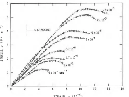
Figure 5 Stress-strain results for
columnar-grained S-2 ice of aver- age grain diameter of 4 to 5 mm at
- 10°C subjected to truly con- stant strain rates [2] as indicated
Figure 6 Theoretical stress-strain diagrams for test conditions in Fig. 5.
Temperature - 10°C (0.96Tm), d =
4.5 mm.
ice [8, 521, as may be seen in data compiled by Gittus ([53, Table 4.7A1). The value of E, determined experi- mentally [lo], also agrees well with that calculated from single-crystal elastic constants [54].
Stress-strain diagrams for pure columnar-grained S-2 ice at 0.96Tm (- 10" C) are reproduced in Fig. 5 [2]. Theoretical predictions for these test conditions are presented in Fig. 6. Agreement, qualitative as well as quantitative, between theory and experiment on the stress-strain (and hence time) diagram may be con- sidered to be excellent, and therefore encourages examination of the details. As the maximum stress or strength is of general interest, this aspect will be dis-
cussed first. Fig. 7 illustrates the strain-rate depen- dence of upper yield failure stress, a,, and failure strain, E ~ . It also includes new test results (Fig. 1). The
theory seems to justify, even in numerical terms, the empirically obtained power law between a, and i:
proposed earlier [2]
where P (= 21 2) andp (= 0.345) are constants; E0 is the unit strain rate (= 1 sec-I).
Both theory and experiment show that failure strains are small ( < 0.15%) and that the strain-rate
S T R A I N R A T E ,
<
(see-l)Figure 7 Dependence of upper-yield fail-
ure stress and strain on strain rate. Tem- perature - 10°C, S-2 ice, d = 4.5
+
0.5 mm. Experimental points (0) from Sinha [2], (@) new tests. (-) Theory,(- - -) empirical power law [2].
1 1 I l 1 1 l l I I 1 l l l l i l
-
-
--
-
-
0-
-
0-
cn-
-
-
-
-
w-
-
-
a-
-
-
C-
-
Y O\-
0,-
oi=
-
l o 2 =_ --
-
-
a-
-
L L OO\ -9
-
-
-
-"L
-
-
-
-
-
l o 1 1 I I I t I I I I 1 1 1 1 1 1 1 1 1 I 1 ( 1 1 1 1 1 l I 1 1 1 1 1 1 1 L 1 0 - 8 1 0 - 1 0 - ~ 10- S T R A I N R A T E ,<
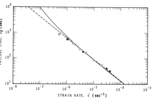
( s ~ c " )Figure 8 Dependence of upper- yield failure time on strain rate. Temperature - 10°C, S-2 ice, d = 4.5mm
+
0.5mm. Experi-mental points ( 0 ) from Sinha [2], ( 0 ) new tests. (-) Theory,
(---) I, = 7.3 x 10⁻³&-082 [21.
sensitivity of E,, given by the exponent of 6 , is signifi- cantly less than that of a,. The theory shows, however, that the empirical power law between E, and i: [2] should not be applied to lower rates. This power law was derived from the experimentally observed depen- dence of failure time t , on E,
where to = 1 sec, Eo = I sec-I. Since E, = trE/toEo, it gives
Experimental values for Q and q were, respectively, 7.3 x and 0.82 (Fig. 8).
Equations 27 and 28 give
This equation bears a remarkable similarity to the dependence of tensile creep rupture time on stress for metals and alloys at high temperatures [4, 5, 71. The limitations of the empirically fitted Equations 28 and 30 can be seen in Figs 8 and 9; clearly they cannot be applied to lower rates.
The theory indicates an increasingly longer failure time, as the strain rate decreases, than that given by the empirical relation. As a consequence, a reversal of
the E,-& relation is predicted in Fig. 7 (instead of the
decreasing E, given by Equation 29). This change in the ductility of the material is, in fact, understandable. Mixed-mode failme, involving wedge cracking, should eventually (at some low rates) go through a transition where the growth of rounded cavities would play an important role [55], until at some even lower rate it would flow without any cracking or void formation. In this case Equation 16 will apply and the stress will asymptotically reach a value that depends on the strain rate (in reality, diffusional flow would com- plicate the flow stress and its dependence on strain
Figure 9 Dependence of failure time on stress. Temperature - 1O0C, S-2 ice, d = 4.5 mm
0.5 mm. Exper~mental points ( 0 )
from Sinha [2], ( 0 ) new tests.
(-) Theory, (---) 1, = 2.4 x
-
--
-
w-
E - E + E + E e d v-
- €d,-
-
- e e l-
--
1 1 1 1 1 1 1 1 1 1 1 1 1 1 1 1 1 0 1 0 20 30 4 0 5 0 6 0 7 0 80 9 0 (b) TIME,t
( 5 0 ~ )strain rate at this peak stress must equal the sum of the viscous strain rate and delayed elastic strain rate. As the latter quantity is small, the rate-controlling mech- anism at failure and during the post-failure regime is dominated by the viscous strain rate.
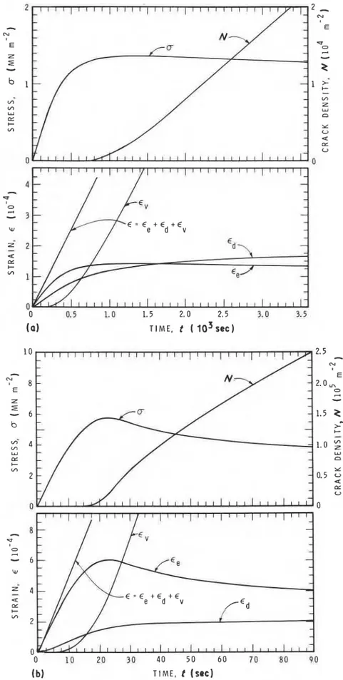
Note the asymptotic approach of the viscous strain rates to values close to the imposed rates in Fig. 12. Clearly, it is the reason for strong, almost one-to-one
Figure 12 Stress, crack density and strain components for strain rates of (a) 5 x 10-'secC', (b) 5 x l ~ - ~ s e c ~ ~ . Tempera- ture - 10°C, d = 4.5 mm.
numerical correspondence (i.e. l/p z n and P-'IP z E,,) established between the empirically obtained strain-rate dependence of strength (Equation 27) and the power-law dependence of viscous flow rate on stress (third term in Equation 16) for conditions in which the crack density is still reasonably low [2]. Such a numerical correspondence, however, cannot be estab- lished if conventional test systems with low stiffnesses
are used. In this case the imposed specimen strain rate would vary during loading. This theme will be pre- sented elsewhere. It is appropriate, however, to men- tion here that the theoretically predicted dependence of cracking activity during loading, shown in Fig. 12, bears a close resemblance to those actually observed in pure S-2 ice [56] using acoustic emissions and conven- tional test machines.
r Estimation of the number of grains in a plane can
be made by N, = l/[n(d/2)2]. In columnar-grained material, N, gives the grain density if the plane is normal to length of the columns. For d = 4.5mm,
N, = 6.3 x l O ~ ~ m - ~ and is shown in Fig. 10. At failure, one crack develops for every 50 grains at 1 x
10-'set-I.
This ratio increases to about one crack for every three grains at 1 x 10⁻⁴sec-'. The crack density even at failure is therefore reasonably low for loading conditions E < 1 x 10⁻⁴sec-'.The present theory is valid for conditions of non- interacting cracks, so that a 2 N 6 1 or, according to Equation 19, x d 2 ~ / 2 4 x 3'12 4 1. The value of the left- hand side, corresponding to the failure crack density at 1 x 1OP4sec-', is 0.035. Thus, for strain rates less than 1 x lop4, cracks can be assumed to be non- interacting even to failure.
Since the delayed elastic strain increases with decrease in grain size for the same value of the g.b.s. displacement, whereas the crack size decreases with
I decrease in grain diameter, the grain size influences the
I strain components in a complex manner. The effect of
i
i
grain size on the rate sensitivity of the strength and 1 stress-strain diagrams has been examined and will bepresented elsewhere because of space limitations. Briefly, it has been found that the rate sensitivity of strength is not affected by grain size, but the failure strain and crack density at failure increase significantly with decrease in grain size, and the strain reversal point shifts to higher strain rates. Thus, fine-grained material behaves in a more ductile manner than coarse-grained material.
9. Summary and conclusion
A non-linear constitutive equation for high tempera- tures has been presented. It consists of elastic, delayed- elastic and viscous components corresponding to three micromechanisms: lattice deformation, inter- granular sliding and intragranular dislocation motion. The model incorporates the predictability of the onset of cracking activity and damage accumulation due to the mechanism of high-temperature grain- boundary embrittlement. Grain-facet long cracks develop when a critical grain-boundary sliding (g.b.s.) displacement or an equivalent delayed elastic strain is reached. Further damage is given in terms of the excess g.b.s. displacement over its critical value. As cracks form, they enhance the matrix deformation affecting the overall creep rate, leading to a minimum rate and then tertiary creep.
Formulations have been developed, using this model, for predicting the deformation and cracking activity for conditions of constant strain-rate strength tests. The theory was tested with published experi- mental data on the strain-rate sensitivity of the
compressive strength of transversely isotropic, col- umnar-grained, pure polycrystalline ice with a load applied in the plane of isotropy. Calculations using material constants were obtained from constant-stress creep experiments totally independent of the strength tests. One-to-one correspondence of theory and experi- ments was noted for the dependence of strength, fail- ure strain and failure time on strain rate. The theory therefore predicts the empirically obtained relations between these quantities. It also points out the limita- tions of the empirical relations, for example the non- applicability of the empirically obtained power-law relation between t, and a, or between E~ and i: at rates
lower than the experimental range.
The theory predicts a critical strain rate, k c , below which no wedge cracks form. For ice, E,
-
2.2 x 1 0 - 8 s e c ~ ' at 0.96Tm ( - 10°C). At E < E, the flow stress increases with deformation and asymp- totically approaches a steady-state value depending on E . With increase in strain rate, E > E,, microcracks develop during loading and stress-strain diagrams exhibit a distinct "upper yield type" failure in which the stress increases to a peak value and then decreases with further strain. This maximum stress, or strength, shows a power-law rate sensitivity similar to that of the matrix or dislocation creep (viscous) rate, without any crack enhancement. Continuity in the a,-E rela- tion is maintained, therefore, over a wide E range. The failure strain E ~ , however, decreases as E increases fromE, and indicates a point of minimum ductility at some strain rate. It increases again with further increase in E. This reversal point is a result of the rate dependence of the relative contributions of the three strain com- ponents to total strain. It occurs primarily as a result of the opposing effects of viscous strain and elastic strain. For E > E,, stress and the time to onset of cracking activity depend on E, as does the level of damage or the crack density at a,. At these strain rates the predicted cracking rate increases monotonically with time and approaches a nearly constant value during the post-upper yield period, thus explaining the phenomenological observation of direct dependence of cracking rate on steady-state flow rate.
Acknowledgements
The author is indebted to R. Jerome for development of the computer program and assistance at all stages of this work. This publication is a contribution from the Institute for Research in Construction, National Research Council of Canada.
References
1 . N K S I N H A , Exper. Mech. 21(6) (1981) 209. 2. Idem, J. Muter. Sci. 17 (1982) 785.
3. 1. F l N N I E and W . R . H E L L E R , "Creep of Engineering Materials" (McGraw-Hill, New York, 1959) p. 114.
4. F. G A R O F A L O , "Fundamentals of Creep and Creep- Rupture in Metals" (Macmillan, New York, 1965). 5. F. K G . O D Q V I S T . "Mathematical Theory of Creep and
Creep Rupture", 2nd Edn (Clarendon, Oxford, 1974), Ch. 10, pp. 131-140.
6. A . J . P E R R Y , J. Muter. Sci. 9 (1974) 1016.
7. Y. N. R A B O T N O V , "Creep Problems in Structural Mem- bers" (North-Holland, Amsterdam, 1969) p. 358.
Phil. Mag. A43 (1 98 1) 665.
M . F . A S H B Y and H . J . F R O S T , in "Constitutive Equations in Plasticity", edited by A. S. Argon (MIT Press, Cambridge, Mass., 1975) pp. 117-147.
N . K , S I N H A , Phil. Mag. 40 (1979) 825.
Idem, J. Mater. Sci. 21 (1986) 1533.
L . W . G O L D , "The Failure Process in Columnar-Grained Ice", NRC 12637 (National Research Council of Canada, Division of Building Research, 1972).
Idem, Phil. Mag. 26 (1972) 3 11.
D. M. C O L E , "Effect of Grain Size on the Internal Frac- turing of Polycrystalline Ice", Report 86-5 (US Army Cold Regions Research and Engineering Laboratory, Hanover, New Hampshire, 1986).
R . C . G I F K I N S , in "Fracture", edited by B. C. Averbach, D. K. Felbeck, G. T. Hahn and D. A. Thomas (Wiley-Inter- science, New York, 1959) pp. 579-623.
G . W . G R E E N W O O D , in "Interfaces", edited by R. C. Gifkins (Butterworths, London, 1969) p. 223.
H. N A H M , D. J . M l C H E L and J . M O T E F F , J. Mater.
Sci. 8 (1973) 104.
D . G . M O R R I S and D . R . H A R R I E S , ibid. 12 (1977) 1587.
D . M c L E A N , "Grain Boundaries in Metals" (Clarendon, Oxford, 1957) pp. 322-337.
J . D . P A R K E R and B . W I L S H I R E , Mater. Sci. Eng. 43 (1980) 271.
A. N . S T R O H , Proc. R. Soc. A223 (1 954) 404.
D . M c L E A N , in "Vacancies and Other Point Defects in Metals and Alloys", Monograph and Report Series No. 23 (Institute of Metals, London, 1958) pp. 159-198.
N . K . S I N H A , J. Mater. Sci. 19 (1984) 359.
Y u . K . Z A R E T S K Y , B . D . C H U M I C H E V and V . I . S O L O M A T I N , Eng. Geol. 13 (1979) 299.
E. S M I T H and J. T. B A R N B Y , Met. Sci. J. 1 (1967) 56.
J. A . W I L L I A M S , Acta Metall. 15 (1967) 1559.
A . H . C O T T R E L L , Trans. Amer. Inst. Min. Engr. 212 (1958) 192.
N . K . S I N H A , in "Proceedings of IUTAM Symposium on Deformation and Failure of Granular Materials, Sept., 1982, Delft, edited by P. A. Vermeer and H. J. Luger (Balkema, Rotterdam, Netherlands, 1982) pp. 323-30.
J . I N T R A T E R and E. S . M A C H L I N , Acta Metall. 7
(1959) 140.
R. G . F L E C K , D . M . R . T A P L I N and C . 1. B E E V E R S , ibid. 23 (1975) 415.
T . W A T A N A B E , Met. Trans. A 14A (1983) 531.
N . K . S I N H A , Exp. Mech. 18(12) (1978) 464.
J . I N T R A T E R and E. S . M A C H L I N , J. Inst. Metals 88 (1959-60) 305.
K . E. P U T T I C K and R. K I N G , ibid. 80 (1951-52) 537.
P . R . S T R U T T , A . M . LEWIS and R . C . G I F K I N S , ibid. 93 (1964-65) 71.
Received 3 November 1987
I
36. T . G . L A N G D O N , "The Microstructure and Design of Alloys", Vol. 1 (Institute for Metals - The Iron and Steel Institute, 1973) p. 222.
37. C . A . P . H O R T O N , "Grain Boundaries" (Institute of Metallurgists, London, 1976) p. E l .
38. R . S . G A T E S , Mater. Sci. Eng. 27(1977) 115.
39. N . K . S I N H A , in Proceedings 6th International Con- ference on Fracture (ICF6), Dec., 1984, New Delhi (Per- gamon, Oxford, 1984) pp. 2295-2302.
40. C . Z E N E R , in "Fracturing of Metals" (American Society
and accepted 25 February 1988
for Metals, Cleveland, Ohio, 1948) p. 3.
41. J . B . C O N W A Y , "Stress-Rupture Parameters: Origin, Cal- culations and Use" (Gordon and Breach, New York, 1969). 42. G . D . J O H N S O N , J . L. S T R A A L S U N D and G , L.
W I R E , Mater. Sci. Eng. 28 (1977) 69.
43. S . N . Z H U R K O V , Int. J. Frac. Mech. l(1965) 311.
44. L. W . G O L D , in "Physics of Snow and Ice", Part I,
edited by H. Oura (Institute of Low Temperature Science, Hokkaido University, Japan, 1966) pp. 359-70.
45. G . M . B A R T E N E V and Y u , S . Z U Y E V , "Strength and Failure of Visco-elastic Materials" (Pergamon, Oxford, 1968) p. 164.
46. V. I . V L A D I M I R O V , Inl. J. Frac. 11 (1975) 869.
47. A . V E N K A T E S W A R A N and D . P . H . H A S S E L M A N ,
J . Mater. Sci. 16 (1981) 1627.
48. D , A . M I L L E R and T . G . L A N G D O N , Met. Trans. A
11A (1980) 955.
49. J . W E E R T M A N . Trans. Amer. Soc. Metals 62(2) (1969)
502.
50. D. P . H . H A S S E L M A N and A . V E N K A T E S W A R A N ,
J . Muter. Sci. 18 (1983) 161.
51. N . K . S I N H A , J. Cold Regions Sci. Technol. 8 (1983) 25.
52. J . W E E R T M A N , in "Physics and Chemistry of Ice",
edited by E. Whaliey, S. J . Jones and L. W. Gold (Royal Society of Canada, Ottawa, 1973) pp. 320-337.
53. J . G I T T U S , "Creep, Viscoelasticity and Creep Fracture in Solids" (Wiley, New York, 1975).
54. N . H . F L E T C H E R , "The Chemical Physics of Ice" (Cambridge University Press, 1970) pp. 165-197.
55. A . S . A R G O N , I . W . C H E N and C . W . L A U , in Pro- ceedings IUTAM Symposium on Three-dimensional Consti- tutive Relations and Ductile Fracture, edited by S. Nemat- Nassar, June, 1980, Dourdan, France (North-Holland, Amsterdam, 1981) pp. 23-49.
56. N . K . S I N H A , in Proceedings of Joint Conference on Experimental Mechanics, SESA/Japan Society for Mechani- cal Engineers, Hawaii, 1982, Part I1 (S.E.S.A., Westport, CT, USA, 1982) pp. 767-772.
II
This paper is being distributed in reprint form by the Institute for Research in Construction. A list of building practice and ~esearch publications available from the Institute may be obtained by writing
to
the Publications Section, Institute for Research in Construction, National Research Council of Canada, Ottawa, Ontario, KIA 0R6.
Ce document est disuibu6 sous forme de tirt-&-part par 1'Institut de recherche en construction. On peut obtenir une liste des publications de I'Institut portant sur les techniques ou les recherches en matikre de bitiment en ecrivant B la Section des publications, Institut de recherche en construction, Conseil national de recherches du Canada, Ottawa (Ontario), KIA 0R6.