Characterization of Redundant UHF Communication Systems for
CubeSats
by
Stephen J. Shea Jr. B.S. Astronautical Engineering United States Air Force Academy, 2014
SUBMITTED TO THE DEPARTMENT OF AERONATICS AND ASTRONAUTICS IN
PARTIAL
FULFILLMENT OF THE REQUIREMENTS FOR THE DEGREE OF
MASTER OF SCIENCE IN AERONAUTICS AND ASTRONAUTICS
AT THE
MASSACHUSETTS INSTITUTE OF TECHNOLOGY
JUNE 2016
C 2016 Massachusetts Institute of Technology. All rights reserved.
Signature of Author: Certified by: Accepted by: MASSACHUSETTS INSTITUTE OF TECHNOLOGY
JUN 2 8 2016
LIBRARIES
ARCHIVES
Signature redacted
Department of AfironauticWoUnd
XeronaTtics
May 19, 2016_____Signature
redacted
KerCahoy Assistant Professor of Aeronautics and Astronautics Thesis Supervisor
Signature redacted
/
Paulo C. Lozano Associate Professor of Aerofautics and Astronautics Chair, Graduate Program CommitteeThe opinions expressed in this thesis are the author's own and do not reflect the view of the United States Air Force, the Department
Characterization of Redundant UHF Communication Systems for
CubeSats
by
Stephen Joseph Shea, Jr
Submitted to the Department of Aeronautics and Astronautics
on , in partial fulfillment of the
requirements for the degree of
Master of Science in Aeronautics and Astronautics
Abstract
In this thesis we describe the process of determining the likelihood of two different Ultra High Frequency (UHF) radios damaging each other on orbit, determining how to mitigate the damage, and testing to prove the radios are protected by the mitigation. The example case is the Microwave Radiometer Technology Acceleration (MiRaTA) CubeSat. We conducted a trade study over three available radio architectures: primary radio and a beacon, high speed primary and low speed backup radios, and two fully capable radios. MiRaTA's communication architecture is a high speed primary radio and a low speed backup radio. This configuration was chosen to balance between capability and size, mass and power requirements.
We present the process of redesigning the communication from its first revision with a primary radio and a beacon to a high speed primary radio and a low speed backup radio. We discuss the important factors that drive the architecture decisions and then the radio system component selections for CubeSat radios. The main factors for MiRaTA were form factor and power efficiency. The primary radio is the L-3 Cadet-U Radio and the backup radio is a MIT custom Micron Radio based on the Planet Labs Low Speed Transceiver's design. The Cadet Radio is 468 MHz and 3 MHz bandwidth for downlink and 450 MHz and 20 kHz for uplink. The Micron Radio is 401 MHz downlink, 450 MHz uplink and both signals have a bandwidth of 20 kHz. The primary and backup radios are both UHF-band, which means there is a risk of the radios damaging each other on orbit that we must factor into design and testing.
After presenting the process of determining the damage thresholds of the radios and the signal strength they need to be protected from. We find that the backup radio may be at higher risk of being damaged than the primary radio, and discuss mitigation strategies. Our goal is to modify the communication system design to make sure neither radio is damaged. After reviewing the available methods of mitigations, we decided to add a limiter to the backup radio and add a high pass filter to protect the primary radio.
We test the mitigation strategies on both radios. We find that with the limiter installed on the backup radio, it can be connected to a signal generator with power incremented up to 25 dBm (which is 8 dB above the damage threshold without including a limiter) without a degradation in
performance. We install a filter on the primary radio's input, and demonstrate that it attenuates the backup radio's signal without degrading the primary radio's performance. We then test both radios together in a test representative of operational scenarios and find that they appear to be sufficiently protected. We discuss the success of this approach and how flight testing should be conducted as well as how it might be implemented on other CubeSats.
Thesis Supervisor: Kerri Cahoy
Acknowledgments
A great number of people of have helped me along the way to my Master's. First and
foremost is my advisor Professor Kerri Cahoy. She was willing to take a chance on me and pushed me to learn a new focus of spacecraft engineering. And I have learned so much about communications.
I would like to acknowledge Mike Shields at Lincoln Laboratory, from whom I learned
so much about RF engineering. A significant portion of the knowledge I applied in this thesis I learned directly from him and another significant portion of the testing was done with him. I would also like to acknowledge Mike DiLiberto at Lincoln Laboratory with whom I learned how operate and test the Cadet as well as properly plan tests and operate Ubuntu. Andy Siegel of Lincoln Laboratory was another significant teacher during a circuit level testing campaign of the Cadet. I would like to acknowledge Col John Kuconis, USAF (ret.) and Bill Blackwell for selecting me for the LL Military Fellows Program and finding funding for me to attend MIT and work with the many great engineers at Lincoln Laboratory.
I would also like to acknowledge everyone on the Microwave Radiometer Technology
Acceleration (MiRaTA) team. It has been a pleasure working with you all. It has been fantastic getting to know many in the MIT community, particularly those at the AeroAstro Muddy Fridays and those in the Tech Catholic Community. I'd like to acknowledge those that helped get to MIT, such as my many mentors at United States Air Force Academy like Lt Col David Barnhart,
USAF. Lastly I would not be where I am today without the incredible love and support of my
Table of Contents
A b stra ct ... 3 Acknowledgm ents... 5 List of Figures... 9 1 Introduction... 12 1.1 Introduction ... 121.2 Exam ples of CubeSat Failures ... 12
1.2.1 AAU-1... 12
1.2.2 CAPE-1... 13
1.2.3 M icroM A S-1 ... 14
1.3 M iRaTA Overview ... 17
1.4 Redundant Com m unication System s... 18
1.4.1 Prim ary Radio and Secondary Beacon Architecture ... 18
1.4.2 Primary High Speed Radio and Low Speed Back Up Radio Architecture... 19
1.4.3 Two Full Capability Radios Architecture ... 20
1.5 M iRaTA 's Radio Architecture D ecision... 20
1.5.1 Overview ... 20
1.5.2 Rationale Against Beacon and Primary Radio Architecture... 22
1.5.3 Rationale Against Two Fully Capable Radios Architecture... 23
1.5.4 UHF Band Conflict ... 23
1.5.5 Methods for Mitigating Interference with Multiple UHF Radios... 24
1.5.6 MiRaTA's Two Radio Interference Mitigation Approach ... 27
2 Approach... 28
2.1 M icron Radio Decision ... 28
2.1.2 Radios Considered ... 31
2.2 Im plem enting the M icron Radio ... 34
2.2.1 Options... 34
2.2.2 Decision ... 35
2.3 Dam age Analysis Approach... 35
2.3.1 Basic Radio Design ... 35
2.3.2 A ssessing Dam age Potential... 36
2.3.3 Determ ining Dam age Thresholds ... 37
2.3.4 Determ ining Expected Power Input... 39
2.3.5 M itigation M ethods... 40
3 M itigation Analysis and Decision... 41
3.1 Determ ining Dam age Thresholds... 41
3.1.1 L-3 Cadet-U Radio... 41
3.1.2 M IT M icron Radio... 43
3.2 Determ ining the Power Input ... 44
3.2.1 Antenna Isolation Tests... 44
3.2.2 Pow er Output Tests... 46
3.3 Determ ining the M itigation... 47
3.3.1 L-3 Cadet-U Radio... 47
3.3.2 M IT M icron Radio... 50
3.3.3 Other Considerations ... 51
4 Spacecraft H ardware Tests ... 52
4.1 M icron Radio Lim iter Test... 52
4.2 Bandpass Filter and M icron Radio Test ... 54
4.4 EM Com bined Radio Test... 57
4.4.1 Set up ... 58
4.4.2 Procedure ... 65
4.4.3 Results... 66
5 Conclusion and Future W ork ... 67
5.1 Conclusions ... 67
5.2 Lessons learned ... 68
5.2.1 Late D esign Change ... 68
5.2.2 Filter Specifications ... 68
5.3 Other M itigation M ethods ... 69
5.3.1 Increasing the D istance Betw een Antennas... 69
5.3.2 Orthogonal Antenna Orientations... 70
5.3.3 Sw itches ... 71
5.3.4 D ifferent Frequency Bands ... 71
5.4 Future W ork ... 71
5.4.1 Flight M odel Com bined Radios Test... 71
5.4.2 Other A ntenna Configurations Test ... 72
6 W orks Cited ... 73
Appendix A: MiRaTA Cadet - Wallops Flight Facility Link Budget... 75
List of Figures
Figure 1: AAU-1 Cubesat (AAU, n.d.)...13
Figure 2: CAPE-1 (CAPE, n.d.)...14
Figure 3: M icroM AS-1 (Blackwell 2013)...15
Figure 4: M iRaTA Nominal Science Operations M aneuver... 18
Figure 5: CAD M odel of M iRaTA (Cordeiro 2015) ... 21
Figure 6: Switch Configurations ... 26
Figure 7: Basic Radio Schematic...35
Figure 8: Signal Path That Risks Damage ... 37
Figure 9: Summary of the Primary Radio's Thresholds... 42
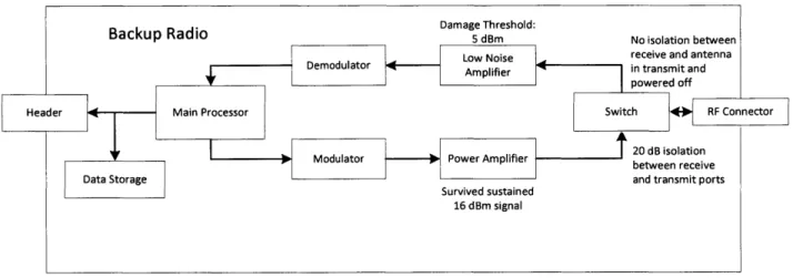
Figure 10: Summary of the Backup Radio's Thresholds ... 43
Figure 11: M iRaTA model used for Antenna Isolation tests ... 45
Figure 12: M icron Radio Power Test Set Up ... 46
Figure 13: Cadet Radio with Protection Highlighted... 48
Figure 14: External Bandpass Filter Characteristics... 49
Figure 15: M icron Radio with Protection Highlighted ... 51
Figure 16: Block Diagram of the M icron Radio Limiter Test ... 52
Figure 17. M icron Radio Functional Testing Block Diagram ... 53
Figure 18: Bandpass and M icron Radio Block Diagram ... 55
Figure 19: Cadet Ground Station Block Diagram... 56
Figure 20: Block Diagram of the Combined EM Radios Test ... 63
Figure 21: Partially Assembled M ass M ockup with Both Radios... 64
Figure 22: EM Combined Radios Test Setup...65
List of Tables
Table 1: M iRaT A's Frequencies ... 21Table 2: EyeStar Replacement Trade Study... 31
Table 3: W ire Antenna Isolation Tests ... 45
Table 4: EM Antenna Isolation Tests ... 45
Table 5: M ax Power Output... 46
Table 6: Power Input to the Radio... 46
Table 7: Data from M icron Radio Limiter Test ... 54
Table 8: M icron and Filter Data ... 55
Table 9: EM Combined Radios Test Component Serial Numbers ... 63
Key Nomenclature
MiRaTA UHF MicroMAS-AAU LEO GMSK Kbps MHz MIT SSL MIT LL Mbps OQPSK RF NASA ESTO GPSRO NORAD TLE Cadet ADCS EPS BPSK SWaP VHF NSL COTS DPDT FCC NTIA PPM dBm LNA SNR dB EM PA DevTool TIB LED ASCII 1Microwave Radiometer Technology Acceleration Ultra High Frequency
Micro-Sized Microwave Atmospheric Satellite Aalburg Unversity
Low Earth Orbit
Gaussian Minimum Shift Keying kilobits per second
Megahertz
Massachusetts Institute of Technology Space Systems Lab
MIT Lincoln Laboratory Megabits per second
Offset Quadrature Phase Shift Keying Radio Frequency
National Aeronautics and Space Administration Earth Science Technology Office
Global Positioning System radio occultation North American Aerospace Defense Command two-line element
L-3 Communications Cadet-U nanosat radio
Attitude Determination and Control System Electrical Power System
Binary Phase Shift Keying Size, Weight, and Power Very High Frequency NearSpace Launch custom off the self
Double Pull Double Throw
Federal Communication Commission
National Telecommunications and Information Administration Pluggable Processor Module
milliwatts in decibels low noise amplifier
signal to noise ratio Decibels
engineering model power amplifier Development Tool Top Interface Board Light Emitting Diode
SDL Space Dynamics Laboratory
USRP Universal Software Radio Peripheral
UART Universal Asynchronous Receiver/Transmitter
USB Universal Serial Bus
1
Introduction
1.1 Introduction
Cubesats are an inherently risky enterprise; there are many opportunities for failure. The communication system is as susceptible to failure as any other subsystem, and a total communications failure leads to complete mission failure. Of failures for the first 100 CubeSats,
17% were attributed to the communication subsystem and 45% were no contact (Swartwout 2013).
It is reasonable to assume a significant portion of the no contacts were from communication failures. Another alternative is a power subsystem failure, which would mean the radio would be incapable of starting. In no contact scenarios, it is impossible to separate failures, between communications and other subsystems. Communication failures can be caused by a variety of circumstances, for example power amplifier failure, insufficient link, and antenna deployment failure. In Sections 1.2.1-3, we describe real examples of CubeSat failures: AAU-1, CAPE-1, and MicroMAS-1.
1.2 Examples of CubeSat Failures
1.2.1 AAU-1Aalburg University (AAU) in Denmark launched AAU-1, a 1U CubeSat, in 2003. Its purpose was to hold a simple camera payload as a technology validation of their CubeSat concept. The ground segment was an amateur radio design. It was launched into Low Earth Orbit (LEO). It transmitted Gaussian Minimum Shift Keying (GMSK) at 9.6 kilobits per second (kbps) at 437 Megahertz (MHz), the UHF amateur band, and used two dipole antennas. The AAU-1 team had trouble with their radio contractors being unable to provide a working product and changed radios
late in the process. This resulted in less time spent ground testing. On orbit, the AAU- 1 team had difficulties closing the link with their satellite. AAU- I's radio had the ability to beacon and the team was able to use data from beacon packets to determine the cause of failure. AAU- 1 used a connection oriented version of the AX.25 protocol, which is more complex than the connection less variation because of the greater handshaking. The satellite and ground station were not establishing consistent enough contact to complete initial handshaking. This led the satellite to appear unresponsive. The team was able to salvage some mission goals through a small subset of commands that did not require the full handshaking protocol because of an established back door, but they could not fully complete their mission. The troubleshooting and lessons learned would not have been possible without the beacon capability, though they concluded they did not include all of the essential housekeeping (Ostergaard 2004).
Figure 1: AAU-1 Cubesat (AAU, n.d.)
1.2.2 CAPE-1
The Cajun Advanced Picosatellite Experiment (CAPE-1) was designed and built at the University of Louisiana and launched in 2007. CAPE-1 was a 1U CubeSat using Frequency Shift Keying at a frequency of 437.245 MHz (Klofas 2016). The team spent significant effort trying to make their CC 1020 radio chip transmit with a protocol that worked with a set of custom off the self (COTS) amateur radio equipment for their ground station. The CAPE team did not spend enough time and testing on making the receive capabilities function while on the ground. The team
-had spent too much time on the downlink capability of the radio because they were attempting to use the transmitter out of its design parameters. Using a different transmitter that was designed to work with the ground station amateur components would have let the team prioritize time differently. Close to launch, the team started testing the radio's receive functions and learned that was not capable of receiving. The satellite was not capable of receiving commands when launched
(CAPE, n.d.).
Figure 2: CAPE-1 (CAPE, n.d.)
1.2.3 MicroMAS-1
The Micro-Sized Microwave Atmospheric Satellite (MicroMAS-1) was a CubeSat designed and built by the Massachusetts Institute of Technology (MIT) Space Systems Lab (SSL) and MIT Lincoln Laboratory (MIT LL). MicroMAS was a 3U CubeSat that used the L-3 Cadet-U Radio. The uplink was 9.6 kbps FSK at 450 MHz and the downlink was 3 Megabits per second (Mbps) Offset Quadrature Phase Shift Keying (OQPSK) at 468 MHz. The ground station is the 18 meter at Wallops Flight Facility, Wallops Island, Virginia. The purpose of MicroMAS was a technology demonstration of a rotating microwave radiometer for measurements of atmosphere
conditions primarily around and inside convective thunderstorms, tropical cyclones, and hurricanes (Blackwell 2013).
Figure 3: MicroMAS-1 (Blackwell 2013)
The MicroMAS operations team was able to successfully communicate with their satellite for only three passes. The successful passes were March 4, 5, and 9 of 2015. After March 9, the operations team were unable to hear a response from MicroMAS. The team examined all aspects of the communication chain. They were able to determine that the uplink chain was working by commanding the satellite into a high drag profile and measured a noticeably increased orbit decay. This troubleshooting testing and received telemetry from the earlier passes indicated there was a failure in the transmit chain.
The MicroMAS team investigated possible causes of the failure. One suspected case was during ground testing. While attached to other spacecraft components, the flight model radio transmitted uncommanded while the radio's radio frequency (RF) connector was not properly terminated. The signal was then reflected back into the radio causing significant damage to both
the radio, particularly the power amplifier, and the rest of the connected components. The radio was sent back to the vendor for inspection and repair, and they replaced the power amplifier. Other components in the spacecraft were also evaluated, tested, and replaced. The MicroMAS team then acceptance tested the radio and reinstated its flight model status. The MicroMAS team concluded that it was possible that the subsystem may have still had degraded or damaged components that
could have contributed to the on-orbit transmit failure.
The cause of failure was determined from the power data collected during the three successful overpasses. One solar panel's telemetry was not matching the curve of generated power in the power model created by the MiRaTA Power Team. There was a second anomaly in the telemetry; one of the Earth Horizon Sensors in the ADCS showed no change in value, likely meaning it was either malfunctioning or obscured. The Power Team altered the power model to determine what the curve should look like if the solar panel was only partially deployed at different angles. The on orbit telemetry matched closest with the panel deployed 20 degrees from the spacecraft body (Hein 2016). MicroMAS-l's antenna was stored underneath the antenna in question. If not properly deployed, the antenna might have suboptimal characteristics, such as reflecting a higher percentage of the outgoing signal back into the radio. If the reflected signal is strong enough, it could damage the PA over time leading to complete failure of the PA. The MicroMAS team decided this is the most likely cause of the MicroMAS failure, though the ground test failure might have contributed.
MicroMAS-1, AAU-1, CAPE-1 are only a representative sample of CubeSat
communication failures though they represent three different types of failure: failure to establish an on-orbit link, issues in ground testing, and inability to transmit on orbit.
1.3 MiRaTA Overview
MicroMAS was the predecessor to the Microwave Radiometer Technology Acceleration (MiRaTA). The MiRaTA mission is funded by National Aeronautics and Space Administration
(NASA) Earth Science Technology Office (ESTO) to use a 3U CubeSat for technology
demonstrations of an all-weather sounding microwave radiometer for measurements of temperature, humidity, and cloud ice, as well as a Global Positioning System radio occultation (GPSRO) receiver for calibration of the radiometer. The GPSRO payload is the Compact TEC/Atmosphere GPS Sensor (CTAGS) and is developed by Aerospace Corporation (Blackwell 2014). MicroMAS and MiRaTA are the first steps towards an eventual fleet of larger CubeSats that provide weather observations with greater geospatial coverage and more frequent revisits than a large monolithic weather satellite. The Time-Resolved Observations of Precipitation structure and storm Intensity with a Constellation of Smallsats (TROPICS) mission is a MIT LL lead project planned for that purpose.
The measurements and calibration are accomplished during MiRaTA's science maneuver. MiRaTA's normal operations orientation is the payload in the ram direction with radiometer's aperture pointing towards the Earth. The GPSRO antenna in this orientation points in the zenith direction. To begin the science maneuver, MiRaTA pitches up so that the radiometer can measure signals emitting through the atmosphere above the Earth's horizon. The spacecraft continues to pitch up in order for the GPSRO instrument, CTAGS, to be able to see at least 4 GPS satellites through the same region of the atmosphere. At the end of data collection, MiRaTA pitches back down and returns to its normal operations orientation. Figure 4 shows this maneuver. One of the payloads can produce up 60 kbps during the 15 minute science maneuver, resulting in a significant amount of data. If the satellite only executes one pass per day, it needs to downlink more 700
Megabits per day. The need for a significant downlink rate is a driving requirement of the communication system.
* 15 minute maneuver
0.5* I sec rate
44
1 roJave sounding Atmospheric GPS Radio OcUlt &
Figure 4: MiRaTA Nominal Science Operations Maneuver'
1.4 Redundant Communication Systems
Because of the high rate of failure and the fact that communications failures often lead to complete mission failure, the MiRaTA team decided to include a redundant communication system. The desire is to prevent complete mission failure and at a minimum be capable of downlinking spacecraft status and troubleshooting the primary radio if needed. In this section, we discuss possible ways to include redundancy on the MiRaTA mission and rationale for each.
1.4.1 Primary Radio and Secondary Beacon Architecture
The team explored three possible options for redundant communication systems. This simplest is the primary radio and a beacon architecture. This is a common choice for CubeSats.
'Blackwell 2014, using the edited version from Cordeiro 2015
According to Bryan Klofas' table of CubeSat communication systems, 28 of the first 100 CubeSats with radios specified had both a radio and a beacon. Those that only had beacon were not counted (Klofas 2016). A beacon is a simplex radio that transmits periodically. These transmits are used to assist in locating the satellite and, in many cases, receiving small amounts of spacecraft status packets. This is very useful for CubeSats which normally rely on North American Aerospace Defense Command (NORAD) two-line element (TLE) sets for location data (NORAD 2016). TLE sets can accumulate significant amounts of error and were not intended to be used as the primary source of orbit determination data (Riesing 2015). Beacons are typically small, because they only have a transmit chain, and therefore take relatively less volume than a standard spacecraft radio. Beacons have low data rates in the singles of kbps to close the link, minimize bandwidth to aid frequency approval, and spacecraft housekeeping data can typically be sent with the low data rate.
A beacon increases the ability of the operations team to locate the satellite and determine possible
causes of failure if they have not heard from the primary radio.
1.4.2 Primary High Speed Radio and Low Speed Back Up Radio Architecture Another architecture option is a primary high speed radio and low speed back up radio. This architecture is seen often in CubeSats, for example, Planet Labs' more than 70 Dove spacecraft (Klofas 2016). The advantages of this architecture are that the low speed radio is smaller than the high speed radio, it has uplink and downlink capabilities, and it is low cost, mass and power compared to a high speed radio. A low speed data radio normally will have a similar power draw as a beacon though they are generally larger because they also have receive components. The disadvantages of this approach are that the radio cannot replace the primary radio completely, and it requires additional mitigation and complexity as will be discussed later in Section 3.3. For CubeSats with primary radios that have a low data rate, this architecture is the same as adding a
second primary, therefore the CubeSat is following the next architecture which is discussed in Section 1.4.3.
1.4.3 Two Full Capability Radios Architecture
The third case we considered for redundant communications is two fully capable radios, whether they are the same or different models. This set up has the most capability and completely prevents mission failure in the case when the "primary" radio stops working. This approach requires the most volume, mass, and cost. This architecture is generally avoided by CubeSat teams because part of the CubeSat philosophy is that CubeSats are supposed to accept higher risk than larger satellites in order to drive down cost and schedule and it may be difficult to accommodate within the allocated budgets.
1.5 MiRaTA's Radio Architecture Decision
1.5.1 Overview
To meet project goals while working within volume, mass and cost constraints, the MiRaTA team selected the primary high speed radio and back up low speed back up radio architecture. The primary radio is the L-3 Communications Cadet-U nanosatellite radio (Cadet) that is a revised version of the only radio on MicroMAS-1. While the Cadet failed on orbit, its capability of 3 Mbps downlink is needed for mission success because of the large amount of data produced by both payloads on orbit. The Cadet's footprint, 74 by 69 millimeters, and thermal dissipation needs led us to design a board in the avionics stack to interface with the Cadet and housing (Kneller 2012). The avionics stack also includes the Attitude Determination and Control System (ADCS), the Electric Power System (EPS) board, the battery, the motherboard, and a second interface board. For the backup radio, we decided to use an in house altered radio design
U
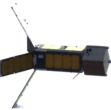
based the design of Planet Labs' Low Speed Transceiver, which is labeled D3-400-T in Bryan Klofas' table. The MIT version of the radio is named the Micron Radio. The Micron Radio is a simple design and through a simultaneous redesign of the spacecraft motherboard, was able to be positioned within the avionics stack on the motherboard. The communication system is designed so that each radio is independent of the other and therefore MiRaTA has a monopole antenna for each radio. The antennas are placed on ram face and extend 180 degrees from each other, as can be seen in Figure 5. They are placed so that they can be stowed between the solar panels and the
spacecraft chassis during launch.
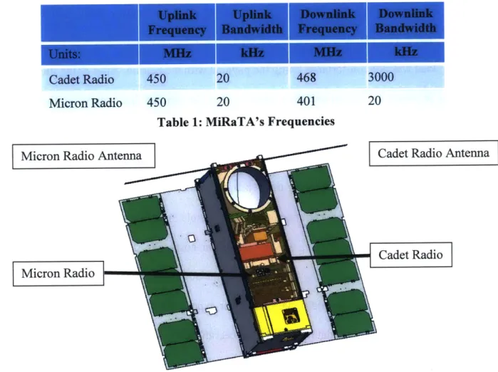
Uplink Uplink Downlink Downlink
Frequency Bandwidth Frequency Bandwidth
Units: MHz kHz MHz kHz
Cadet Radio 450 20 468 3000
Micron Radio 450 20 401 20
Table 1: MiRaTA's Frequencies
Micron Radio Antenna Cadet Radio A
Micron Radio
ntenna
1.5.2 Rationale Against Beacon and Primary Radio Architecture
At the beginning of the MiRaTA project, a beacon was added to the satellite design, the NearSpace Launch (NSL) EyeStar Beacon. The beacon outputs 200 mW at 1616.25 MHz. The signal is 36 bytes per second Binary Phase Shift Keying (BPSK). Its form factor is 44 mm x 80
mm x 8 mm. NSL designed the EyeStar Beacon to work with the GlobalStar satellite constellation.
The advantage of this beacon was that Globalstar satellites would see it multiple times per orbit.
If a Globalstar satellite could have heard the beacon, the data would have been piped to a website
that the team would have had access to. The service was paid for by megabyte and therefore would have been more expensive than the standard downlink with an amateur radio ground station (NearSpace, n.d.). The problem with this beacon was that the contractor that was designing the GPSRO payload was not comfortable flying the payload with the beacon. After doing the analysis on coupling between the beacon and their receiver, they determined that even when the GPSRO payload was turned off there was a possibility that part of the payload could be degraded when EyeStar Beacon transmitted because the frequencies were too close.
The full trade study for replacing the beacon with the Micron Radio will be discussed in Section 2.1. During this process we learned that it was possible to replace the beacon with a backup radio with only adding minimal size, weight and power costs. We decided that the additional capability of being able command the spacecraft and the ability to possibly troubleshoot and fix the primary radio was worth the additional cost. After experiencing a transmit chain failure with MicroMAS-1, the ability to get data off of the spacecraft was prioritized. Our eventual solution was a backup radio that was implemented with even less size, weight, and power (SWaP) than the original beacon.
1.5.3 Rationale Against Two Fully Capable Radios Architecture
The two full capable radios architecture did not work for multiple reasons. Primarily, there were not any radios with data rates above 1 Os of kbps that would fit in the spacecraft along with the primary radio. With two payloads and only 3U of volume, MiRaTA is volume limited. Also, in addition to not being able to fit a second Cadet, the team did not think that adding a second Cadet would significantly improve the risk of a full communications failure on orbit.
1.5.4 UHF Band Conflict
Both of MiRaTA radios transmit and receive in the UHF band. This adds additional complexity compared with when the project had a UHF radio and an L-band beacon. Antenna gain characteristics change based on frequency. When two radios have frequencies that are sufficiently different, the gain of an antenna for the other radio's frequency is so low that the other radio's signal is negligible. The exception to this is if the antenna is close to a harmonic, or multiple of the base frequency, of the other radio. At close harmonics, the antenna would have a small but significant gain.
For projects that have the ability to use radios with sufficiently different frequencies different frequencies and without being near harmonics of each other, the mitigation and testing covered in this thesis are not necessary. S band radios will typically not interfere with UHF radios.
S band radios are able to use patch antennas which don't need to be deployed, and are more
directional than monopole antennas. The disadvantages of S band are that most radios designed for CubeSats are intended to be a primary radio, their shapes and size of the radio are larger, and the S band is a higher frequency leading to more path length loss. Due to COTS S-band radios being larger that the spaces available in MiRaTA's design, the only options for a backup radio
were UHF and Very High Frequency (VHF). For a team that can use an S band radio, it had advantages over UHF and VHF.
VHF and UHF are common choices for CubeSats because of the amateur radio bands around 145 MHz and 437 MHz. Using one of each might not provide enough isolation for both radios because the UHF band is close to the third harmonic of the VHF band. The other disadvantage of VHF is the required length of the monopole antenna. Monopole antennas are supposed to be a quarter of the wavelength in order to resonant effectively with the signal near a ground. The satellite chassis acts as an imperfect ground. A quarter wavelength for 145 MHz is 52 cm which is longer than every side of the 10 cm x 10 cm x 35 cm satellite. This means that MiRaTA would require a more complex antenna, have to settle for an inefficient antenna, or find a different means of securing the antenna during launch. These disadvantages led the team away from using VHF for the backup radio or beacon.
Having two UHF radios has some advantages. UHF monopole antennas are shorter than the length of 3U making stowing during launch easier. The strong majority of CubeSats have UHF radios. There are many options with a wide range in complexity, form factor, and output power. Having two UHF radios also raised the possibility of having a shared ground station, if the ground station could close the link (have enough gain) for both UHF downlink frequencies; the mission does not intend to ever operate both radios at the same time, however.
1.5.5 Methods for Mitigating Interference with Multiple UHF Radios
There is a very significant disadvantage of using two UHF radios. It is likely for one radio to damage the other due to interference and sensitivity unless properly mitigated. In this thesis, we investigated two basic methods for mitigation: the switch based method and the filter/limiter based method.
1.5.5.1 Switch Based Method
A switch based method protects the radios by grounding their RF connection when the
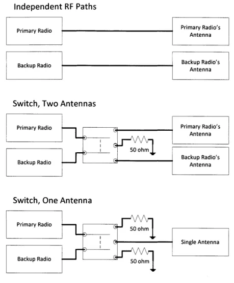
switch is set to the other radio. If the radios have separate chains, a double pole double throw (DPDT) switch is best for most architectures because it forces the inactive radio to ground when the primary radio is connected to the antenna. A switch can be implemented with one antenna or two antennas. Figure 6 outlines both switch implementations. Two antennas can add complexity beyond that added by the DPDT switch by forcing two independent RF paths to intersect, which could be cumbersome if the RF paths do not run close to each other. A single antenna approach is easier to implement because the RF paths have to intersect. The principle is the same with one antenna, but the switch has only one output that leads to the antenna. The other disadvantages of a switch, for either implementation, are that it needs to be powered and it increases the complexity of flight software with timing code. Switches also add an additional single point failure. If the switch fails with the antenna connected to the low data rate radio and the primary radio grounded, a mission like MiRaTA would be unable to complete all of its mission objectives despite a working primary radio.
Independent RF Paths
Primary Radio Primary Radio's
Antenna
Backup Radio Backup Radio's
Antenna
Switch, Two Antennas
Primary Radio Primary Radio's
Antenna
Backup Radio's
Backup Radio Antenna
Switch, One Antenna Primary Radio
Single Antenna
Backup Radio
Figure 6: Switch Configurations
1.5.5.2 RF Component methods
The other method involves using radio frequency (RF) components to protect the radios. The primary options are limiters and filters. Limiters are components that have attenuation values that are dependent on input power. Larger inputs cause a larger amount of attenuation leading to a limiter to limit the power to a certain maximum value. Filters are RF components that are dependent on frequency and can be selected to have high attenuation at one radio's output frequency and low attenuation at the other radio's frequencies. The limiter/filter method requires testing and analysis to determine how much attenuation is required.
1.5.6 MiRaTA's Two Radio Interference Mitigation Approach
To minimize software complexity and to have two completely independent communication paths, the MiRaTA team decided to use the limiter/filter method. The objective of this thesis is to analyze the interference between the two MiRaTA radios, to determine the best filter/limiter approach to mitigating interference, to describe necessary tests for verification and validation, and to document the process in case other teams find it useful.
2 Approach
In order to meet the purpose of this thesis, we will cover the decision to determine the backup radio and the approach for determining the possibility that either radio could damage the other. This information is used to determine the needed mitigation. The mitigation is tested to demonstrate the communication system should function on orbit.
2.1 Micron Radio Decision
The decision to use the Micron Radio over other options was driven by size, input power, ability to close the link, availability of frequency bands, ground station receive interference, COTS availability, responsiveness of vendors, and ground station requirements. As said in Section 1.5, size was the greatest limiting factor. Before a radio was seriously considered, its dimensions and mounting details were sent to the structures lead for a confirmation it could fit.
2.1.1 Key Factors in Backup Radio Decision
2.1.1.1 Power
Because of their comparatively small surface area, CubeSat missions are often power limited. MiRaTA has double deployable solar panels to maximize surface area, but still requires periodic battery charging periods to stay power positive. Any radio decision should try to minimize the power draw necessary to transmit. Most radios have the ability to select an output power so input power has to be considered with radio efficiency and the output power required to close the link. Once the team had narrowed it down to two or three options and calculated link budget for each, input power was an important consideration.
2.1.1.2 Frequency
As discussed in Section 1.5.4, the output and input frequencies determine the interference between the radio and the primary radio. The frequencies also determine antenna type and size.
2.1.1.3 Heritage
How much heritage and what kind of heritage a radio has is a very important factor, which is true for any space component. Ground testing can capture many different aspects of the space environment, such as temperature fluctuations, vacuum conditions, and the radiation environment. It is not possible to perfectly replicate the space environment on Earth, though. Thus proof a design
is robust and effective in space is important.
2.1.1.4 Licensing
Licensing is important but not a deciding factor. The MiRaTA team had a preference for previously licensed radios, which overlaps with both whether or not a radio has heritage as well as frequency bands and ground station interference. The advantages of selecting a radio that has already had a license approved are that there is a better chance the Federal Communication Commission (FCC) or National Telecommunications and Information Administration (NTIA) will approve the radio as they have approved similar. Some vendors included licensing within the purchase price, such as the Eyestar beacon, which substantially reduces the amount of effort required. The biggest influence in terms of licensing was that there is a general climate that the
FCC would stop approving amateur band radios unless the satellites were capable of adding
something to amateur radio community (SpaceNews 2013). While these bands have been historically used by the majority for CubeSats (Klofas 2016), MiRaTA's back up radio would have to deal with licensing issues if it were an amateur band radio. The amateur band has advantages as
well. Amateur radio operators have been historically extremely supportive of helping to locate and track CubeSats.
2.1.1.5 COTS versus Custom
COTS versus custom is significant factor in CubeSat engineering. Most CubeSat programs,
including MiRaTA, prefer to purchase COTS components when they are available and within budget. The approach can reduce costs by purchasing a component manufactured in larger numbers instead of spending time and money to design a component from scratch. It also should minimize the testing needed by the project team because the manufactures test the components before delivery and can provide test reports. This makes COTS more desired in most cases, but custom can also have advantages. Custom components can meet program specific requirements with more efficient designs. Custom components are able to be tailored to different form factors and can save on size, mass and power.
2.1.1.6 Vendor Responsiveness
Another factor is vendor responsiveness. It is undesirable if it is difficult to get information when needed it or if the documentation is not polished enough. The MiRaTA team wanted to avoid this situation so we considered how fast a vendor responded to our questions into our decision.
2.1.1.7 Ground Station
We also weighed the ground station requirements that each radio would have. The main consideration is how much additional work would be necessary to design the ground station electronics. Radios that came with some portions of the ground architecture designed or built were preferred over radios that came with no ground support. Having portions of the ground station
available to incorporate into integration and functional testing saves schedule and reduces risk compared with having to use a from-scratch or temporary ground station configuration.
2.1.2 Radios Considered
The team considered four options: a custom version of the Planet Labs Low Speed Transceiver, the AstroDev Lithium (Astronautical, 2008), the Stensat Radio Beacon (Stensat, n.d.), and the Funcube radio (AMSAT-UK, 2010). We initially considered the Astrodev Beryllium but did not pursue it due to concerns at the time about heritage and the difficulty of fitting an external power amplifier and input low noise amplifier. The following table outlines the four considered radios with their major features and highlights the main issue or issues with the radio.
Duplex or Simplex RF Power Frequency (MHz) DC Power Size (mm) Weight Data Rate to Ground Cost Heritage Stensat Radio Beacon Simplex 1-3 W 144-148 / 420-450 5-12Vdc
@
2A Tx, 40mA idle 44.45 x 78.74 50g 9.6kb/s AX.25 Funcube Half-Duplex 0.4 W 145 (TX)/ 435 (RX) 6.8-8.2Vdc 90 x 96 9.6kb/s AX.25 AstroDev Lithium Half-Duplex 1-4 W 130-450 1OW:5-9Vdc@
1.5A 3.3Vdc @ 70mA 32 x 62 x 8.07 50g 76.8kb/s AX.25$750 per radio - $5000 per radio
CanSat Funcube, RAX-1 & 2,
M-UKUBE-1 Cubed, CSSWE,
CSBN, CubeBug-1, Perseus,
GRIFEX
Table 2: EyeStar Replacement Trade Study
Planet Labs LST Half-Duplex 0.6-1 W 391-464 3.3Vdc
@
IA 10 x 10 x 2 1og 2.4kb/s custom $1000 per spin 71 Planet Labs Doves2.1.2.1 Stensat Radio Beacon
The Stensat Radio Beacon was considered because it was the second choice when the MiRaTA team was deciding on a beacon at the beginning of the project. When we had to remove the EyeStar from the design, we were going to replace it with the Stensat Radio Beacon. After we expanded the trade study to transceivers not just beacons, Stensat was kept as a comparison for size, mass, and power to minimize requirement creep for the team. Stensat was less expensive than any of the half-duplex radios, but it had similar size, mass and power values (Stensat). It was middle of the road for data rate and used the AX.25 data protocol like most of the options. AX.25 protocol is the standard protocol for amateur radio and Stensat's frequencies are in the amateur band (AX.25). By the end of the trade study we had determined that a low data rate back up radio was the best solution, for the reasons discussed in Section 1.5.2, and because the Stensat Radio Beacon was a simplex radio, it was ruled out as an option.
2.1.2.2 FUNcube Radio
The MiRaTA team also considered the Funcube Radio. Funcube was a satellite built by
AMSAT-UK, an amateur satellite community in the United Kingdom (AMSAT-UK 2010). The
main advantage of the Funcube Radio is that it came with the Funcube Dongle. The Funcube Dongle is a COTS ground station board. It was designed to work with the Funcube Radio but is now sold for use in other projects (AMSAT-UK). This was the Funcube Radio's major advantage. It also uses the amateur frequencies and protocol and had some heritage. The Funcube Radio's transmit power was a bit lower than other options. The documentation needed some improvement, and is the reason for the missing parameters in Table 2. It was also not clear what the production and purchasing would be like, and the author notes that the third-party website that was selling the radio does not appear to be doing so any longer. In addition, its uplink and downlink frequencies
were different band and it had a larger volume. Having multiple frequencies in multiple bands means that MiRaTA would need two antennas for one radio. If it shared one antenna with the primary radio, that would add the complexity of a switch in addition to the complexity of multiple antennas that include both VHF and UHF.
2.1.2.3 The Astronautical Development, LLC Lithium Radio
The Astrodev Lithium ended up being the second choice for the MiRaTA team. It has the most direct heritage. The Lithium has flown on at least ten satellites with missions that lasted longer than a month (Klofas 2016). It supported the highest power output and the firmware was capable of the widest range of data rates, up to 76.8 kbps, though we did not have enough link margin for that. It was close to the volume of space that was available for the backup radio. The minor drawbacks for the Lithium radio were its cost, which is low for a primary radio but more expensive than the other backup radio options, and the responsiveness from Astrodev. Astrodev did provide well-made documentation for the Lithium (Astronautical, 2008).
2.1.2.4 Planet Labs Low Speed Transceiver
Planet Labs was generous in providing the design for their Low Speed Transceiver to the MiRaTA project. Planet Labs has launched over 71 Dove satellites that use the Low Speed Transceiver as a secondary radio. The radio has a lower transmit power than the Lithium and Stensat and it has the lowest data rate for all the options. Having the schematic and layout of the board meant that we were able to take advantage of having a "custom" component, while still reducing the amount of work that would have been necessary. With the large number of Doves that have the used the radio, its design has more heritage than the Lithium, but because the layout was altered, the Micron Radio cannot be considered to have all of that heritage. The support we
received from Planet Labs was also a factor. Beyond providing the design, they were responsive to the team's questions, provided a ground station board and its schematic and layout, and gave us the code that they had been using to command to the ground station board. Planet Labs is in the process of open-sourcing the radio, expecting to do so by the end of 2016. We decided that making a custom board based on their design was the best choice.
2.2
Implementing the Micron Radio
2.2.1 Options
The MiRaTA project had three options for implementation of our version of the radio. The simplest was minimally changing the board and securing it where the team had planned for the backup radio to be mounted. For reasons discussed in Section 3.3.2, this would not have been significantly better in terms of heritage because it became necessary to significantly alter the board's layout, though we did not know that at the time of the decision. All layout work was accomplished by the Avionics team, and experts at MIT LL reviewed their design.
The second and third options required a redesign of the motherboard as well. The motherboard originally was a Pumpkin Pluggable Processor Module (PPM). The PPM had a great deal of capability that was not necessary for MiRaTA. The Avionics team determined that they would be able to simplify the board enough to include the parts from the Low Speed Transceiver. The second option included the redesigned motherboard with the radio sitting on top of the motherboard as a separate daughterboard. This freed up space in the ram section of the spacecraft that would have been used for the other radios. This redesign did require a significant amount of time and effort from the MiRaTA Avionics and Flight Software teams. The third option was including the radio components directly on the motherboard. This would have additional complications with separating RF and analog components and preventing interference.
2.2.2 Decision
The team decided that the best course of action was the second option. It freed up volume in the spacecraft and simplified the motherboard to the necessary components. The third option
did not gain the project anything over option two; it added additional complication and required
more time to develop.
2.3 Damage Analysis Approach
2.3.1 Basic Radio Design
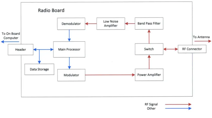
In order to motivate a discussion of what kinds of interference or damage the radio could be susceptible to, we describe the basic components in a radio, as shown in Figure 6.
Radio Board
Demodulator lie- -- Band Pass Filter
To On Board
Computer To Antenna
Header Main Processor Switch RF Connector
Data Storage
Modulator Power Amplifier
RF Signal
Other
Figure 7: Basic Radio Schematic
The main processor of the radio is the core component of the radio. It controls all of the radio's active components, communicates with the spacecraft processor and handles data storage if the radio is designed to support data and storage management. Beyond the processor, the radio can be broken into two major parts: the transmit chain and the receive chain.
The transmit chain starts with the main processor sending a data string to the modulator. The modulator creates the signal based on the data string. Modulators normally have low output power. For example, the CCl1 01 's maximum output power is 12 dBm, or 16 mW (Texas Instruments 2015). This is much lower than standard 27 to 33 dBm for a CubeSat radio, as shown in Table 2. Following the modulator is a power amplifier, in order to increase the signal power to the desired level. Some radios have filters or other RF components to manipulate the signal before it reaches the switch and exits the radio.
Incoming signals go through the switch to a bandpass filter or low noise amplifier (LNA).
A bandpass filter is used to increase the signal to noise ratio (SNR) by removing out of band noise.
A LNA is used to set the SNR and boost the power to aid with demodulation. The signal is
converted to bits by the demodulator and the bits are sent to the main processor.
Many components can be combined. A chip like the CC I101 can be the main processor, the demodulator and the modulator.
2.3.2 Assessing Damage Potential
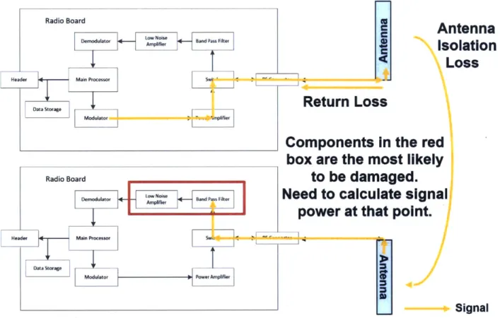
After deciding on a radio, analysis was performed to determine to what extent one radio could damage the other. There are multiple paths for the signal from one radio to reach the other. The main path is the signal radiated from one antenna to the other. The signal output from the antenna and so the power is relatively high for the opposite radio's receiver. Another path for interference is from coupling between the coaxial cables that connect the radios to their antennas, which is typically much lower than -30 dB below the signal.
The two characteristics that were tested for were the radios' damage threshold and the signal power they experience when the other radio is transmitting. When trying to determine the damage threshold of the radio, each major component should be looked at, starting at the RF
antenna connector. The transmit chain normally has a higher damage threshold because they are designed to withstand part of the signal being reflected back into the power amplifier by a load that is not perfectly matched. The radio's damage threshold is often set by the first component in the receive chain. Usually, the LNA is the most sensitive to damage due to its high gain and location in the signal path. The signal path between the radios is shown in Figure 8 with the most likely area of damage outlined in the figure. Figure created by author.
Radio Board
Demodulator Band Pass Filter
Main Processor Swi,
Lr Modulator .nplifier
Radio Board
I ow Noise Br Pslie
1eodlator ndastAplifierr
Header Main Processor
DOata Storage
Modulator Power Amplifier
I ________________________________________
Antenna
Isolation
Loss
Return Loss
Components in the red
box are the most likely
to be damaged.
Need to calculate signal
power at that point.
__ Signal
Figure 8: Signal Path That Risks Damage
2.3.3 Determining Damage Thresholds
Determining the limiting component can be done in two ways: through vendor-supplied information and through testing. Vendor-supplied information is the easier method. Most data sheets include the component's damage threshold. With a little analysis, components that are further from the switch can have their damage thresholds expressed in terms of power input into
Header
the radio. Testing is the more difficult method to determine damage threshold, because it can be difficult to determine if a part is actually damaged. Complete failure is noticeable but determining the damage threshold and how to protect a radio is more difficult. We are defining the damage threshold as where repeated application of the signal will significantly shorten the radio's lifetime, which shortens the spacecraft's mission. This threshold can be determined by extensive testing to prove the failure point over many cycles with multiple radios, which is too expensive for a CubeSat project. The threshold can be approximated from the complete failure point with some margin of safety, but this does not have more fidelity than using vendor supplied numbers. When a part is being tested for an atypical condition, an approximation based on testing is the best available option.
Part of the analysis focused on the switch state, whether it was set to transmit, receive, or powered off. While not used for MiRaTA, turning the radio's internal transmit/receive (TX/RX) switch to transmit could potentially give the radio enough margin to protect its sensitive components while the other radio is transmitting. We investigated the isolation between the receive and transmit ports and between the antenna and receive and transmit ports on both radios. Another portion of the testing investigated how much isolation existed if the switch was powered off and not set in either direction. The radios have electronic switches so, unlike mechanical switches, the neutral state does not necessarily direct the full signal to one chain. This method has many complications and risks. First, the radios must have hardware capable of powering off only the switch and the firmware to command it. Second, this adds complexity to the flight software by requiring it to send correctly timed series of commands to protect the radios during every transmit. Third, it adds many undesirable failure modes for the spacecraft. If the switch is unable to be turned on correctly, a transmit would cause significant damage if the signal has no means of exiting the
radio. If there is a software error and the switch does not turn off, then a transmit would damage the other radio. This method is a software solution and the MiRaTA team preferred hardware solutions.
2.3.4 Determining Expected Power Input
After determining the damage thresholds of a radio's components, the expected power of the signal needs to be determined. There are two aspects to this. The first is the output power of the each radio. The maximum output should be measured and used for this assessment even if the program is planning on using a lower power level on orbit as a conservative measure. The program might need to use maximum power if there are issues closing the link on orbit, so it is best to plan around this worst case. This data is collected by connecting the radio to a power meter and adding attenuation as needed for the measurement. The power is determined by adding the amount of attenuation to the power value recorded when the radio is transmitting at max power.
The second value needed is the isolation between the antennas. This is measured by creating a model of the spacecraft. This model does not need to be a high fidelity mockup, just the correct shapes. Holes and inconsistencies significantly smaller than a tenth of the radios' wavelength are not important, nor are internal components. For MiRaTA, the important parts were the two antennas, the 3U structure, and the deployed solar panels, which were modeled by a single sheet of metal. The antennas were tuned before the testing to maximize output from each transmitter. Improperly tuned antennas would make the antenna isolation appear higher than would be experienced on orbit. We used a network analyzer to transmit a carrier over one antenna and measured how much returned on the other antenna. This value was repeated for both antennas with their respective transmit frequencies.
With the antenna isolation values and radio power values, the power seen at the other radio is able to be calculated. If it is higher than the damage threshold of the other radio, then mitigation is necessary. The difference between the power seen and the damage threshold is the minimum that must be mitigated, but the 5 to 10 dB should be added as a factor of safety.
2.3.5
Mitigation Methods
As discussed in Section 1.5.5.2, there are two main components that can be used to protect radios: limiters which have attenuation values that scale with input power to limit the maximum power and filters that have attenuation dependent on frequency. Limiters are best when the only concern is minimizing power level at a certain point. For example, a limiter would counterproductive if it is in the transmit chain where the desire is to maximize power. A limiter does not work outside of the radio, because it would limit the transmit signal to the antenna, which means that limiters are not a possibility when trying to protect a COTS radio such as the Cadet, whose internal layout and components we are not able to easily modify. Filters are generally larger components than limiters but can be designed to let one signal through with minimal attenuation, have a set amount of attenuation for another frequency, and can be employed between the radio
and its antenna.
Another mitigation method is to lower the output power of one or both of the radios. This option can make it difficult to close the link and because it is likely a software fix, it adds an operation risk of commanding too much power. If only a few dB are needed to protect the radios, this is the simplest method and has no hardware changes. The method with filters or limiters is lower risk than lowering the power.
3 Mitigation Analysis and Decision
MiRaTA has two UHF radios. The MiRaTA team needed to determine if they were at risk of damaging each other. The main analysis for this thesis is determining the damage thresholds of the two radios, the power delivered from one radio to the other, and the needed mitigation for MiRaTA to survive on orbit operations. In Section 3.3.3 and Section 5.3, we discuss other possible mitigation approaches that we could not use with MiRaTA but which may be useful for other programs.
3.1 Determining Damage Thresholds
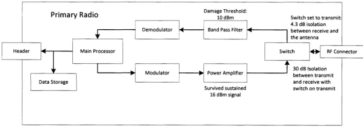
3.1.1 L-3 Cadet-U Radio
The first step in determining the required mitigation is defining the damage threshold of each radio. We assume a representative value that might be appropriate for the damage threshold
of the Cadet for this example, such as 10 dBm. We decided to test the power amplifier and the atypical switch conditions because they were not experiencing the signal under normal conditions. The team was able to purchase same power amplifier component as the Cadet's power amplifier (PA). The output was connected to a signal generator and a load was put on the input. The power amplifier was powered on and the signal generator was set to transmit at 401 MHz. The signal generator was turned on and the output power was progressively increased to 16 dBm. The input current to the power amplifier was carefully watched to detect any abnormalities. The signal generator was then disconnected from the PA's input and attached to the input. The output of the power amplifier was connected to 50 dB of attenuation and a spectrum analyzer. A 468 MHz signal at 5 dBm was input into the PA and produced a 34 dBm signal. This was in family with PA data
taken at other times. We concluded that the Cadet's power amplifier could withstand up to a 16 dBm signal.
While exploring the possibility of turning the switch into different configurations, the MiRaTA team tested the switch in different configurations. An evaluation board for the Cadet's switch was purchased. The configuration was when the switch was set to transmit. A network analyzer was connected to the receive line of the switch and to the switch's output. The network analyzer measured 4.3 dB of isolation with the switch set to transmit. The network analyzer was connected to receive and transmit ports on the switch. When the switch was set to transmit, the network analyzer measured 30 dB of isolation. The below figure summarizes the findings.
Primary Radio D 10 T d Switch set to transmit:
4.3 dB isolation Demodulator Band Pass Filter 4 between receive and
the antenna
Header Main Processor Switch *0- RF Connector
7
T - 30 dB IsolationModulator -- Power Amplifier between transmit
Data Storage and receive with
Survived sustained switch on transmit 16 dBm signal
Figure 9: Summary of the Primary Radio's Thresholds
Without considering the switch state, we considered the representative damage threshold of the Cadet to be 10 dBm as this was the lower of the values representing the receive and the transmit lines. The damage threshold is compared against the power that is input into the Cadet Radio during a Micron Radio transmit. The switch data is used during the discussion for possible mitigation methods.