HAL Id: hal-01511071
https://hal.archives-ouvertes.fr/hal-01511071
Submitted on 20 Apr 2017
HAL is a multi-disciplinary open access
archive for the deposit and dissemination of
sci-entific research documents, whether they are
pub-lished or not. The documents may come from
teaching and research institutions in France or
abroad, or from public or private research centers.
L’archive ouverte pluridisciplinaire HAL, est
destinée au dépôt et à la diffusion de documents
scientifiques de niveau recherche, publiés ou non,
émanant des établissements d’enseignement et de
recherche français ou étrangers, des laboratoires
publics ou privés.
conformance relations
Anais Guignard, Jean-Marc Faure, Gregory Faraut
To cite this version:
Anais Guignard, Jean-Marc Faure, Gregory Faraut. Model-based testing of PLC programs with
appropriate conformance relations. IEEE Transactions on Industrial Informatics, Institute of Electrical
and Electronics Engineers, 2017, �10.1109/TII.2017.2695370�. �hal-01511071�
Model-based testing of PLC programs with
appropriate conformance relations
Anais Guignard, Jean-Marc Faure, Member, IEEE, Gregory Faraut, Member, IEEE,
Abstract—Numerous theoretical results have been obtained in the field of conformance testing, a very promising formal tech-nique to improve dependability of critical systems. Nevertheless, developing on this basis PLC test techniques that produce correct conformance verdicts requires to take into account the real technological features of PLC. This paper proposes conformance relations that meet this objective. Examples illustrate the benefits of the contribution.
Index Terms—Conformance test, Programmable Logic Con-troller, Critical systems, Test verdict, Test duration, Mealy machine
I. INTRODUCTION
Since around twenty years, numerous researches have been carried out to improve PLC1(Programmable Logic Controller)
programs development by using formal methods based on well-defined models ([1], [2]). These works have yielded several worthwhile results in the domains of design ([3], [4], [5]), verification ([6], [7], to name a few) or implementation ([8]) of PLC programs. Whatever the benefits of these works, they are not integrating experiments on real PLC and assume that the whole program, in an IEC 61131-3 language for instance, is known, at the end of design or before verification or implementation. This knowledge is not the main concern of the end-users of critical automated systems. On the other hand, these users want to be sure that the PLC that executes this program behaves as specified, on the basis of experiments; this means that, whatever the current values of the PLC inputs and outputs and the sequence of inputs that is sent to the PLC, it generates the sequence of outputs that is planned in the specification. This explains why conformance testing is gaining a strong interest in industry and is advocated ([9], [10], for instance) for controllers of critical systems, like railway transport, power production and distribution.
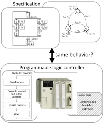
The overall aim of conformance testing is indeed to check experimentally whether an implementation, seen as a black-box with inputs and outputs, behaves as specified. In this paper, the implementation will be a PLC which executes cyclically a control code that may have been generated automatically2from
the specification or not. The objective of this test technique
A. Guignard, J.-M. Faure and G.Faraut are with LURPA, ENS Cachan, Univ. Paris-Sud, Universit´e Paris-Saclay, 61 avenue du Pr´esident Wilson, F-94235 Cachan France, e-mail: [email protected]
1The acronym PLC, in the singular form, will be used throughout this
article to represent a unique controller or a set of controllers.
2When the PLC code has been automatically generated from the
specifica-tion, testing permits to check the correctness of the generator, i.e. to check whether the semantics implemented in this generator is the same than the one which is understood by the designer of the specification, which is often not the case.
(Figure 1) is to check whether the execution of this code by the PLC conforms to the specification, only by observing the output changes in response to the input changes; the code itself is unknown (black-box approach). It must be underlined that, compared to test techniques based on simulation [11], conformance testing does not require to build a model of the controlled plant; hence, the test results are more generic.
Fig. 1. Objective of conformance test of a PLC
Several worthwhile theoretical results have been obtained in the domain of model-based conformance testing by using different formal specification models: Mealy machines -or finite state machines- ([12], [13]), Petri nets [14], labeled transitions systems [15]. They have been mainly applied to test communication protocols [16]. More recently, conformance testing of PLC that control critical systems has been addressed [17], [18]; in this work, the specification is represented as a Mealy machine, a formalism for Discrete Event Systems with inputs and outputs which is well-suited to describe the external behavior of a PLC. This formal specification can be obtained from a model in a tailor-made language, as presented in [19]; another example of such a translation of a model
in an industrial language into a formal model may be found in [20]. Selecting this formalism implies that only non-timed systems will be considered in what follows. A timed model, in the form of a timed automaton for instance, may be indeed non-deterministic, e.g. because the time intervals that define the guards of two concurrent transitions starting from the same state are overlapping. To be selected as the specification of a controller, which must be compulsorily deterministic, such a model shall be previously determinized, by using for instance the formal techniques presented in [21]. However, these worthwhile theoretical results are rather new and will be only considered in further work on model-based testing of PLC.
The aim of this paper is to improve the previous results on model-based conformance testing of PLC by proposing two conformance relations that allow correct test verdicts to be delivered in a reduced time. In the previous works indeed [22], the conformance verdict was delivered after a predetermined time that corresponded to the longest computation time of all outputs, for every test step; hence, the overall duration of the test was unnecessarily long. The core idea of this paper is to base the conformance verdict on a variable-length sequence of observations of the outputs for several consecutive PLC cycles and not on a unique observation after a fixed time. The number of observations that will appear in the proposed conformance relation will permit to determine the lower bound of the duration of each test step, and consequently of the whole test duration. A beneficial consequence of this choice is that the conformance verdicts are more reliable because incorrect evolutions which lead to a correct state are detected, which was not the case with the previous approach. This article extends the work presented in [23] so that several transitions may be fired sequentially for a unique change of the input values. Moreover, more detailed examples of testing of correct and flawed implementations are given to illustrate the benefits of our proposal.
The outline of the article is the following. A reminder on conformance test of Mealy machines is proposed in the second section. The experimental conditions of test execution on PLC are given at section III. Section IV permits to define conformance relations that lead to correct conformance verdicts; these relations are exemplified on cases of correct and flawed programs. Concluding remarks and prospects are drawn up in the last section.
II. BACKGROUND
A. Formal model of the specification
This work assumes that the industrial specification has been translated into a Mealy machine, a widespread formalism to represent the specification in conformance testing of non-timed systems, as presented in [22], for instance. Formally, a Mealy machine is a 6-tuple M = (IM, OM, S, sinit, δ, λ) where:
• IM is the input alphabet, finite set of input events iM • OM is the output alphabet, finite set of output events oM • S is a finite set of states s
• sinit ∈ S is the initial state
• δ : S × IM → S is the transition function
• λ : S × IM → OM is the output function
The following assumptions will be made to build a confor-mance test sequence from this specification model:
• The transition function is complete and deterministic (i.e. every transition δ(s × iM) with s ∈ S and iM ∈ IM is
defined once and only once).
• The Mealy machine which describes the specification
is minimal. This implies that every state is reachable from the initial state and distinguishable. More details on minimization of Mealy machines can be found in [24], [25], for instance.
• There is no unstable cycle, sequence of more than one transition, all labeled with the same input event, that returns to a state after having left this state. The absence of unstable cycle is a special variant of livelock freedom. It must be noted that self-loops are possible because a self-loop includes only one transition; hence, it is not considered as an unstable cycle.
B. Faults model
When the specification and the implementation are both represented by Mealy machines which satisfy the previous assumptions, the implementation conforms to the specifica-tion iff their I/O languages are equivalent; hence, language equivalence is the conformance relation. This relation is not satisfied when the implementation contains at least one of the following faults:
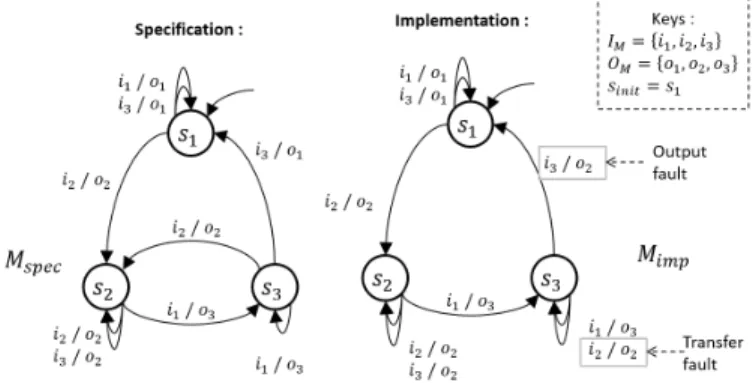
• output faults: when a transition is fired, the correct state is reached but the output event which is emitted is not that expected (output label of the transition in the specification model);
• transfer faults: when a transition is fired, the state which is reached is not that expected (destination state of the transition in the specification model) even if the right output event is emitted.
These two types of faults are illustrated at Figure 2 where the specification model Mspec contains 3 states SM =
{s1, s2, s3}, and is defined from an input alphabet IM =
{i1, i2, i3} and an output alphabet OM = {o1, o2, o3}; this
machine satisfies the above assumptions. The implementation Mimpis defined on the same alphabets but includes one output
fault and one transfer fault.
C. Minimum-length test sequence construction
Two phases must be sequentially performed to test the absence of transfer and output faults in the implementation:
• Construction of a test sequence from the specification
model. This sequence is an ordered list of test steps where a test step includes a couple of an input value that will be applied to the implementation and an output value that is expected. A test objective that defines the coverage percentage of the test must be mandatorily defined before building this sequence.
• Execution of the test sequence by a test-bench, electronic device that sends inputs to the implementation, observes its responses and compare these responses to those expected. Comparison of the observed outputs to the expected ones requires a conformance relation (language equivalence or that proposed in [26] or [27]) has been clearly defined previously.
The first phase is detailed in this subsection; the second phase is described at section III when the implementation is a PLC that executes a control program.
Formally, a test sequence is an ordered list of elementary test steps et = (ss, Iexp, sd, Oexp) where:
• ss×sd∈ S ×S where ssis the source state of a transition
and sd is the destination state of this transition
• Iexp∈ IM, Oexp∈ OM where Iexp (Oexp) is the input
(output) event of the transition in the specification
• sd = δ(ss, Iexp) where δ is the transition function of the
specification
• Oexp= λ(ss, Iexp) where λ is the output function of the
specification
It will be assumed in what follows that the implementation model has the same number of states than the specification. In this case, the strategy to build the test sequence, called T-method [12], is to take at least once each transition of the Mealy machine that represents the specification; the test coverage is called ”all-transitions” in this case. When the im-plementation model includes more states than the specification, other strategies are to be selected [28], [29]. Furthermore, if the implementation is a PLC, it is possible to build one continuous sequence that covers all transitions because it is always possible to return to the initial state from any state, by issuing a reset event that restarts the PLC.
Construction of the test sequence that meets this objective while being minimum-length3 is a well-known optimization problem which can be solved by applying the Chinese postman algorithm to the machine [30]. Moreover, if the implementa-tion under test is a PLC that executes a control code, it is possible to reduce somewhat this sequence [17]. The input events correspond indeed in that case to combinations of logic inputs; when two successive transitions of the Mealy machine share the same input event, for instance the transition (ss, Iexp,
sd , Oexp) and the transition (sd, Iexp, sd , Oexp), self-loop
on the destination state of the previous transition, it is possible to test these two transitions in only one test step because the
3The minimum-length sequence is the sequence that meets the test objective
in a minimum number of test steps.
values of the inputs of the PLC are not modified during this step.
The complete test sequence T S obtained from the specifi-cation model of Figure 2 is given below:
T S = ((s1, i1, s1, o1), (s1, i2, s2, o2), (s2, i1, s3, o3),
(s3, i2, s2, o2), (s2, i3, s2, o2), (s2, i1, s3, o3),
(s3, i3, s1, o1)) (1)
It can be easily verified that this sequence meets the test objective (every transition of the specification is taken at least once) while it comprises 7 test steps and the Mealy machine 9 transitions. This comes from the selected strategy; the transitions (s1, i2, s2, o2) and (s2, i2, s2, o2), for instance,
may be both tested during the second test step. This strategy may be used for every self-loop on a state which is labeled by an input event that is also the label of an incoming transition of this state.
Last, it must be noted that a test sequence does not define the duration of each test step, delay between the occurrences of the input events of two consecutive test steps, that must be greater than the delay between the occurrence of the input event of the first step and the occurrence of the expected output event of this step. This issue really matters however when testing real controllers that are not infinitely reactive; it will be addressed in section IV.
III. TEST SEQUENCE EXECUTION
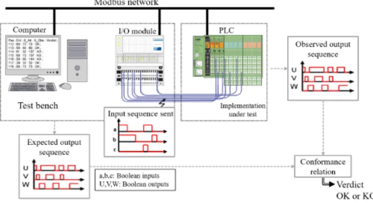
Once a test sequence has been constructed, it must be executed by using the experimental facility which is depicted Figure 3. This figure shows that:
• The test-bench includes a computer that executes the test program and an I/O module. Both devices are connected via a fieldbus.
• The logic inputs of the PLC under test are connected to the logic outputs of the I/O module of the test-bench.
• The PLC is also connected to the computer via the
fieldbus.
Fig. 3. Experimental facility for test execution
The structure of the programs which are executed by the PLC and the computer is shown at Figure 4. The PLC executes
a classical I/O scanning cycle (Fig. 4a) and sends to the computer, through the fieldbus, its output values at the end of every cycle. It must be noted that the control code that corresponds to the computation of the variables (second phase of the cycle) is a priori unknown (black-box approach) and that no additional piece of code is added (non-intrusive approach). For each test step, the test program (Fig. 4b):
• sends to the I/O module an input combination that
cor-responds to the input event of this step, as detailed at section IV-A;
• observes the sequence of outputs that are generated at the end of every cycle by the PLC in response to this input change; the definition of the minimal duration of this observation is the topic of section IV-C;
• elaborates a test verdict on the basis of the observed and expected output sequences and according to the conformance relations which will be defined in section IV-D; once the verdict obtained, the input combination which corresponds to the next test step is sent to the I/O module if the verdict is positive (OK). Test execution is stopped otherwise (verdict KO).
Fig. 4. Structure of the PLC and test programs
To sum up, the PLC under test and the computer commu-nicate via the I/O module and the network; the inputs of the PLC are sent by the computer via the I/O module and the outputs of the PLC at the end of every cycle are transmitted to the computer via the fieldbus.
It must be noted that all inputs of the PLC are changed synchronously by the test-bench and are read synchronously, but not necessarily at the same time, because the I/O module can modify its outputs at any moment of the PLC cycle; hence, the input vector read by the PLC is identical to the input vector defined by the test program. Last, it will be assumed in the sequel of this paper that the internal states of the implementation are observable by the PLC outputs, i.e. a different combination of outputs is associated to every state.
IV. CONFORMANCE RELATIONS
A. Defining alphabet from I/O combinations
Before building the conformance relations, it is important to note that usually a PLC is not an event-driven component but is time-driven, with time stamps defined by the I/O scanning, and does not receive/emit events but logic variables. Hence, the input and output events introduced in the definition of the Mealy machine must be defined from combinations of these variables, as follows.
Let VI (resp. VO) be the set of Boolean input (resp. output)
variables of the PLC. The input alphabet IM (output alphabet
OM) of the Mealy machine that describes the specification is
composed of all the combinations of input (output) variables. The dimension of IM (OM) is |IM| = 2|VI|(|OM| = 2|VO|)
and each element of the input (output) alphabet is represented by a minterm4 defined on V
I (VO).
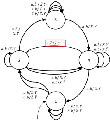
An example of a Mealy machine that represents, with these definitions, the expected behavior of a PLC with 2 input variables VI = {a, b} and 2 output variables VO =
{X, Y } is given at Figure 5. This machine includes 4 states S = {1, 2, 3, 4} and 16 transitions which are all labeled with Boolean combinations5of the input and output variables. This
model will be used as the specification throughout this article.
Fig. 5. Specification of the considered example
An example of correct implementation of this machine in Structured Text language is given at Figure 6.
B. PLC cycle and consequences
Only mono-tasking (or single threaded) PLC which are commonly integrated in automated systems will be considered
4A minterm defined on a set of n Boolean variables is the conjunction of
all these variables in their positive or complemented form.
5(.) represents the operator of conjunction and ( ) represents the
Fig. 6. Example of correct implementation of the Mealy machine of the Fig.5 in PL7Pro
in this work. In this case, the control code is executed according to a cyclic I/O scanning (Fig. 4(a)) that can be periodic or not and comprises 4 phases:
• Inputs reading (R),
• Internal and output variables computation (C),
• Output values updating and transmission (U),
• Waiting time until the end of the period, if the cycle is periodic.6
The two well-known consequences of this scanning are that:
• The response time (delay between the occurrence of an input change and the occurrence of the corresponding output change) is not equal to zero obviously and is variable.
• Asynchronous changes of input variables may be detected as synchronous.
The second issue appears when the PLC is connected to sensors that measure different non-correlated variables; when changes of several of these variables occur at different times during a PLC cycle, they are detected synchronously at the beginning of the next cycle. This is not the case when testing conformance of a PLC because all outputs of the test-bench (inputs of the PLC) are changed synchronously (Figure 7) at the beginning of a test step; therefore, this phenomenon need not to be considered in this work.
Fig. 7. Example of evolutions of input variables during test execution
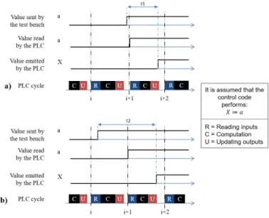
The first issue is illustrated at Figure 8. The response time stands between one (the input change occurs just at the end
6This waiting time is equal to zero for a cyclic but not periodic I/O scanning,
as this is the case in the Fig. 4(a)
of cycle i and is detected just after, at the beginning of cycle i + 1) and two (the input change occurs just at the beginning of cycle i and is detected only at the beginning of cycle i + 1) cycles. The lower and upper bounds of this delay are then one and two periods, if the scanning is periodic, or once and twice the maximal value of the cycle otherwise.
Fig. 8. Minimum (t1) and maximum (t2) response times
C. Duration of a test step
It has been underlined, at the end of II-C, that a minimum-length test sequence obtained from previous works on confor-mance testing of Mealy machines does not define the duration of each test step. The objective of this part is to determine the minimal duration, in term of number of PLC cycles, of each step for three cases:
• test of a self-loop
• test of a transition whose source and destination states are different,
• test of successively fired transitions.
The conformance relation will be stated at the next section from the results of these three analyses.
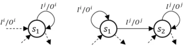
Test of a self-loop: Testing a self-loop means that, from the active state (S1 in Figure 9.(a)), the input values are changed
(from Ii to Ij, Ii ∈ I
M, Ij ∈ IM and Ii 6= Ij in the figure,
assuming that the previous test step was that of the leftmost transition)7 and the expected output is that of the self-loop,
while the active state remains the same. This value is identical to that of the previous test step because the destination state is the same for both transitions and the same output is associated to all transitions leading to a given state to distinguish every state.
According to the discussion of the previous section on the response time of a PLC, the minimum duration of a test step
7The labels of the transitions in this figure and the following ones are
noted as couples of input and output events, for readability reasons, but it is reminded that they correspond to couples of combinations of input and output variables of the PLC.
Fig. 9. (a) A generic self-loop; (b) A transition with different source and destination states
of a self-loop is equal to 2 PLC cycles, to be sure the input change has been correctly detected. This step will include two observations of the output values; these observations must be identical to deliver a positive conformance verdict.
Test of a transition whose source and destination states are different: A similar reasoning can be made for such a transition (Figure 9.(b)); at least 2 PLC cycles are compulsory to test the transition from S1 to S2 after the input values are
changed (from Ii to Ij, assuming that the previous test step was that of the self-loop on S1).
However, when there is a self-loop with the same input value on the destination state, it is possible to test during only one test step both the transition to S2 and the self-loop, as
mentioned at II-C; if the values of the inputs of the PLC are not modified indeed, a correct control code will execute sequentially the two transitions. It is obvious in that case that the test step must last at least 3 PLC cycles (2 for the transition which changes the active state, to be sure that the input change has been detected, and 1 for the self-loop on the destination state, because the firing of this self-loop does not require any input change).
Test of successively fired transitions : The above reasoning can be extended to more than 2 transitions. This will be illustrated on the case of the Mealy machine with three successively firable transitions presented at Figure 10. This structure where a state (S2 in this figure) is both source and
destination of two different transitions that share the same input label may be found when translating a specification in a tailored-made language into a Mealy machine [23].
An input change from Ii to Ij, from the active state S 1,
may provoke the successive firing of three transitions: from S1 to S2, from S2 to S3 and the self-loop on S3. However,
the new input value must remain the same during at least 4 PLC cycles to be sure to observe this sequence of firings; this is the minimum duration of the test step for this input change.
Fig. 10. Example of successively firable transitions
More generally, if a change of the input value may lead to the successive firing of m transitions in the specification model, the test step for this sequence of firings must last at least (m + 1) PLC cycles; the test verdict will be based on the sequence of the (m + 1) output values observed.
D. Definitions
The discussion of the previous section has permitted to de-fine the minimum duration, in term of number of PLC cycles, of a test step. It is now possible to propose a conformance relation based on the sequence of observed outputs at the end of each one of these cycles.
Let sc be the current active state, let Ii ∈ IM and Oi ∈
OM be the current values of the input and output (Boolean
combinations of the input and output variables of the PLC), let Ij be the input value for the considered test step, let Obs =
(Oi, Oj, ...) be a sequence of consecutive observed outputs
and let m be the number of successively firable transitions when the input is changed from Ii to Ij,
Definition 1. The PLC under test is said conform to the specification when a unique transition is tested if the relation (2) is satisfied: Obs = (Oi, Oj) or Obs = (Oj, Oj) withOj such asλ(sc, Ij) = Oj (2)
Then, the new active state of the Mealy machine is defined as sd= δ(sc, Ij).
Definition 2. For the others cases, the PLC under test is said conform to the specification if the relation(3) is satisfied:
Obs = (Oi, O1, ..., Om)
such as
∀Ol, l = 1..m, there is:
λ(sl, Ij) = Ol with s0= sc and sl= δ(sl−1, Ij) or Obs = (O1, ..., Om+1) such as
∀Ol, l = 1..m + 1, there is:
λ(sl, Ij) = Ol with
s0= sc and sl= δ(sl−1, Ij)
(3)
Then, the new active state of the Mealy machine is defined as sd= sm.
The relation (2) must be selected for the test of a unique transition (self-loop or transition with different source and destination states) and the relation (3) for a sequence of m successively firable transitions. In both cases, the minimum sequence of consecutive observations Obs is given for the two cases discussed at IV-B. Observation sequences for a given input change that lead to a positive conformance verdict can be obtained by adding to the right of this sequence any number of observed values which are identical to the last one (Oj for the relation (2) for instance); these sequences are
not minimum-length, however. The benefit of these definitions will be shown in the next section by application to correct and flawed implementations that will be compared to the specification of Figure 5.
E. Examples
From the specification model of Figure 5, the test sequence (4) which starts from the initial state 1 can be built by using the technique presented in section II-C.
T S = (a.b, a.b, a.b, a.b, a.b, a.b, a.b, a.b, a.b, a.b) (4) It is important to note that this sequence is not described in the general form of a test sequence (relation (II-C)); the source and destination states as well as the expected output value, for each test step, are not given. The states have been omitted only for readability reasons; they can be easily determined from the knowledge of the model and the sequence of inputs, if the initial state is known. On the other hand, the absence of the expected output value is explained by the definition of the conformance itself; as this definition is based on a sequence of observations and not only one observation, introducing a unique value does not make sense.
This test sequence contains only 10 terms but meets the objective (every transition is taken at least once) because several transitions are taken sequentially during some steps. The first step is the test of the self-loop on the initial state for the combination where both input variables are True; the minimum duration of this step is two PLC cycles. The transitions from state 1 to state 2, then from state 2 to state 4, then the self-loop on this state are fired during the second step; the minimum duration of this step is four PLC cycles. The longest sequence of successively firable transitions after an input change contains m = 3 transitions (steps 2, 5, 7 and 10).
Case of a correct implementation: The results of the ex-ecution of this sequence with a correct implementation, for instance the ST programm of Fig. 6, are presented at Table I8 where the combination of input variables that is applied
to the PLC, the source and destination states of the sequence of transitions (may be equal to only one transition) which is tested, the intermediate states, if any, the minimum-length observation sequence that is 2, 3 or 4 PLC cycles long and the test verdict are given, for each test step.
Case of flawed implementations: Two flawed implementa-tions will be tested according to the definition of conformance in this section; the first one (Figure 11) includes an output fault, the second one a transfer fault (Figure 12).
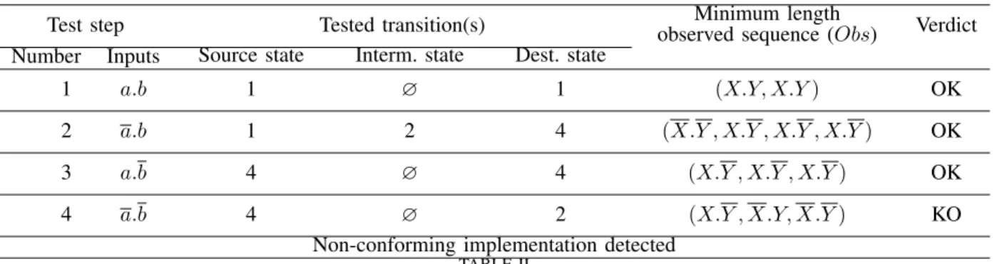
In the model of Figure 11, the output associated to the transition from state 4 to state 2 is X.Y whereas X.Y is expected. The results of the execution of the test sequence (4) on this implementation are given at Table II. The first three test steps provide positive verdicts but for the fourth one that tests the transition from state 4 to state 2 as well as the self-loop on state 2 for the input combination a.b the sequence of output combinations is (X.Y , X.Y, X.Y ) and does not satisfy the relation (3) in the definition of conformance. Obs should be (X.Y , X.Y , X.Y ) or (X.Y , X.Y , X.Y ) according to this relation. The output error is detected; the implementation does not conform the specification.
It must be clearly highlighted that a conformance relation that is based only on the last observation X.Y , as this is the case in previous works, would lead to a positive verdict because the output fault would not be detected. This verdict
8In the following tables, in the column Verdict, OK means that the test is
passed, for the considered test step, KO that the test has failed and ! that the test is non-conclusive. Moreover, the symbol ∅ (empty set) means None.
Fig. 11. A flawed implementation with an output fault
would be non-valid, however; a flawed implementation would be declared correct. This remark shows the benefit of a conformance relation based on a sequence of observations, the only solution to detect flaws during sequences of transitions.
Test step Tested transition(s) observed sequence (Obs)Minimum length Verdict Number Inputs Source state Interm. state Dest. state
1 a.b 1 ∅ 1 (X.Y, X.Y ) OK 2 a.b 1 2 4 (X.Y , X.Y , X.Y , X.Y ) OK 3 a.b 4 ∅ 4 (X.Y , X.Y ) OK 4 a.b 4 ∅ 2 (X.Y , X.Y , X.Y ) OK 5 a.b 2 4 1 (X.Y , X.Y , X.Y, X.Y ) OK 6 a.b 1 ∅ 1 (X.Y, X.Y ) OK 7 a.b 1 2 3 (X.Y , X.Y, X.Y, X.Y ) OK 8 a.b 3 ∅ 3 (X.Y, X.Y ) OK 9 a.b 3 ∅ 3 (X.Y, X.Y ) OK 10 a.b 3 4 1 (X.Y, X.Y , X.Y, X.Y ) OK
TABLE I
CONFORMANCE TEST EXECUTION OF A CORRECT IMPLEMENTATION
Test step Tested transition(s) observed sequence (Obs)Minimum length Verdict Number Inputs Source state Interm. state Dest. state
1 a.b 1 ∅ 1 (X.Y, X.Y ) OK 2 a.b 1 2 4 (X.Y , X.Y , X.Y , X.Y ) OK 3 a.b 4 ∅ 4 (X.Y , X.Y , X.Y ) OK 4 a.b 4 ∅ 2 (X.Y , X.Y, X.Y ) KO
Non-conforming implementation detected
TABLE II
CONFORMANCE TEST EXECUTION OF THE IMPLEMENTATION OFFIGURE11
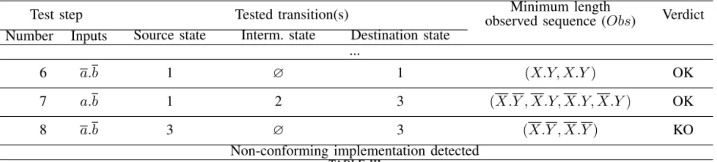
The model of Figure 12 includes a transfer fault9; the transition going from state 2 to state 3 and labeled with the input combination a.b in the specification has been replaced by a self-loop on state 2 with the same input variables combination. The results of the execution of the test sequence (4) are given at Table III. The first six test steps provide positive verdicts, which is quite normal because the part of the implementation which is tested during these steps conforms to the specification; they have been omitted in this table for space reasons. The seventh test step also provides a positive verdict even if the observations are obtained by firing the transition from state 1 to state 2 then the self-loop on state 2 labeled with the input combination a.b and not the sequence from state 1 to state 3 through state 2; but, as the output is the same (X.Y ) for the correct and erroneous transitions, the transfer fault is not detected at this step. It is detected at test step eight where the sequence of observations (X.Y , X.Y ) does not satisfy the relation (2).
9This fault corresponds to a dead code because the state 3 is not reachable.
F. Discussion
To sum up, this section has shown that a conformance relation based on a sequence of observations for several PLC cycles must be used to detect every output and transfer fault during the execution of the conformance test of a PLC.
With this conformance relation, the minimum duration of the whole test sequence, in term of number of PLC cycles, is given by:Pn
i=1mi where n is the number of test steps and
mi the minimal number of PLC cycles for the ithtest step.
The minimal duration of the test sequence (4), for instance, is equal to (5 ∗ 2 + 1 ∗ 3 + 4 ∗ 4) = 29 PLC cycles, because mi is equal to 2 for 5 test steps, 3 for one step and 4 for the
remaining four steps.
The minimum duration defines a realistic lower bound of the duration of the test and not a too pessimistic overestimation obtained by defining a constant value for the duration of every step, as this has been made in previous works.
The values mi are computed off-line, i.e. before test
ex-ecution. Computing mi requires to determine the number of
transitions of the Mealy machine that are successively fired for the considered test step, as exemplified in IV-C. A Mealy machine which describes a specification does not contain any
Test step Tested transition(s) observed sequence (Obs)Minimum length Verdict Number Inputs Source state Interm. state Destination state
...
6 a.b 1 ∅ 1 (X.Y, X.Y ) OK
7 a.b 1 2 3 (X.Y , X.Y, X.Y, X.Y ) OK
8 a.b 3 ∅ 3 (X.Y , X.Y ) KO
Non-conforming implementation detected
TABLE III
CONFORMANCE TEST EXECUTION OF THE IMPLEMENTATION OFFIGURE12
cycle of successively firable transitions; this would mean that the controller is totally unstable for some combination of the input variables, which is surely never expected. Hence, the length of the longest possible sequence of successively fired transitions is equal to |S| (cardinality of the set of states). This sequence crosses indeed once and only once every state and therefore comprises |S| − 1 transitions from the source state to the destination state; the self-loop on this last state must then be fired. Consequently, even if this case is very rare, the maximal computational cost of this off-line analysis is a linear function of the number of states. Our approach scales correctly.
V. CONCLUSION
The numerous and worthwhile theoretical results obtained in the domain of conformance testing of Mealy machines are helpful to develop model-based testing methods of PLC then to improve dependability of critical systems, but must be adapted to take into account the technological features of these automation components that are not infinitely reactive but are based on a cyclic I/O scanning. This paper has shown that, at each test step, the conformance verdict must be based on a sequence of observations of the outputs for several consecutive PLC cycles, to detect every transfer and output fault.
The proposed conformance relations permit us to define the minimum duration of each test step, in terms of number of PLC cycles. Therefore, this work contributes to reduce the time, then the cost, of test, while meeting the test objective and providing reliable verdicts.
On-going work is aiming at extending these results to validation of PLC by using HIL (hardware-in-the-loop) tech-niques. In this case, the PLC is not connected to a test-bench but to a software simulation of the plant to form a closed-loop system. Hence, the state space to analyze is not that of the implementation in isolation but the state space of the implementation constrained by the plant, which is smaller. Up to now, only non-exhaustive simulation has been considered in this approach. Our objective is to investigate whether formal analysis techniques which have been developed for conformance testing of PLC can be used to check completely the correctness of the implementation from sequences of observations of the inputs and outputs of the simulated plant.
ACKNOWLEDGMENT
This work has been funded by the French Research Agency as part of the VACSIM project.
REFERENCES
[1] G. Frey and L. Litz, “Formal methods in PLC programming,” in Systems, Man, and Cybernetics, 2000 IEEE International Conference on, vol. 4, 2000, pp. 2431–2436.
[2] T. L. Johnson, “Improving automation software dependability: A role for formal methods?” Control Engineering Practice, vol. 15, no. 11, pp. 1403 – 1415, 2007.
[3] E. Estevez and M. Marcos, “Model-based validation of industrial control systems,” IEEE Transactions on Industrial Informatics, vol. 8, no. 2, pp. 302–310, May 2012.
[4] V. Vyatkin, “Software engineering in industrial automation: State-of-the-art review,” IEEE Transactions on Industrial Informatics, vol. 9, no. 3, pp. 1234–1249, Aug 2013.
[5] M. Obermeier, S. Braun, and B. Vogel-Heuser, “A model-driven ap-proach on object-oriented PLC programming for manufacturing systems with regard to usability,” IEEE Transactions on Industrial Informatics, vol. 11, no. 3, pp. 790–800, June 2015.
[6] M. Rausch and B. Krogh, “Formal verification of PLC programs,” in American Control Conference, 1998. Proceedings of the 1998, vol. 1, Jun 1998, pp. 234–238.
[7] B. F. Adiego, D. Darvas, E. B. Viuela, J. C. Tournier, S. Bliudze, J. O. Blech, and V. M. G. Surez, “Applying model checking to industrial-sized PLC programs,” IEEE Transactions on Industrial Informatics, vol. 11, no. 6, pp. 1400–1410, Dec 2015.
[8] F. Basile, P. Chiacchio, and D. Gerbasio, “On the implementation of industrial automation systems based on PLC,” Automation Science and Engineering, IEEE Transactions on, vol. 10, no. 4, pp. 990–1003, Oct 2013.
[9] IEC 60880, Nuclear power plants - Instrumentation and control systems important to safety - Software aspects for computer-based systems performing category A functions, 2nd ed. International Electrotechnical Commission, 2006.
[10] IEC 61850-10, Communications Networks and Systems in Substations -Part 10: Conformance testing, 2nd ed. International Electrotechnical Commission, 2005.
[11] M. Barth and A. Fay, “Automated generation of simulation models for control code tests,” Control Engineering Practice, vol. 21, no. 2, pp. 218–230, 2013.
[12] D. Lee and M. Yannakakis, “Principles and methods of testing finite state machines-a survey,” Proceedings of the IEEE, vol. 84, no. 8, pp. 1090–1123, Aug. 1996.
[13] R. Dorofeeva, K. El-Fakih, S. Maag, A. R. Cavalli, and N. Yevtushenko, “FSM-based conformance testing methods: A survey annotated with experimental evaluation,” Inf. Softw. Technol., vol. 52, no. 12, pp. 1286– 1297, Dec. 2010.
[14] H. Zhu and X. He, “A methodology of testing high-level Petri nets,” Information and Software Technology, vol. 44, no. 8, pp. 473–489, 2002. [15] E. Brinksma and J. Tretmans, “Testing transition systems: An annotated bibliography,” in Modeling and Verification of Parallel Processes, ser. Lecture Notes in Computer Science, vol. 2067, 2001, pp. 187–195. [16] C. Jard and T. Jeron, “Tgv: theory, principles and algorithms, a tool for
the automatic synthesis of conformance test cases for non-deterministic reactive systems,” Software Tools for Technology Transfer (STTT), vol. 6, Oct 2004.
[17] J. Provost, J.-M. Roussel, and J.-M. Faure, “Testing programmable logic controllers from finite state machines specification,” in Dependable Control of Discrete Systems (DCDS), 2011 3rd International Workshop on, June 2011, pp. 1–6.
[18] J. Provost, J. M. Roussel, and J. M. Faure, “Generation of single input change test sequences for conformance test of programmable logic controllers,” IEEE Transactions on Industrial Informatics, vol. 10, no. 3, pp. 1696–1704, Aug 2014.
[19] J. Provost, J.-M. Roussel, and J.-M. Faure, “A formal semantics for Grafcet specifications,” in 7th IEEE Conference on Automation Science and Engineering (IEEE CASE 2011), Trieste, Italy, Aug. 2011, pp. 488– 494.
[20] C. Seidner and O. Roux, “Formal methods for systems engineering behavior models,” Industrial Informatics, IEEE Transactions on, vol. 4, no. 4, pp. 280–291, Nov 2008.
[21] N. Bertrand, A. Stainer, T. Jeron, and M. Krichen, “A game approach to determinize timed automata,” in Foundations of Software Science and Computational Structures, ser. Lecture Notes in Computer Science, M. Hofmann, Ed. Springer Berlin Heidelberg, 2011, vol. 6604, pp. 245–259.
[22] J. Provost, J.-M. Roussel, and J.-M. Faure, “Translating grafcet speci-fications into Mealy machines for conformance test purposes,” Control Engineering Practice, vol. 19, no. 9, pp. 947–957, 2011.
[23] A. Guignard and J.-M. Faure, “A conformance relation for model-based testing of PLC,” in 12th IFAC / IEEE International Workshop on Discrete Event Systems (2014), vol. 47, no. 2, 2014, pp. 412 – 419. [24] A. Gill et al., Introduction to the theory of finite-state machines.
McGraw-Hill, 1962.
[25] N. Chandrasekaren and M. Umaparvathi, DISCRETE MATHEMATICS:. Prentice-Hall of India Pvt.Limited, 2015. [Online]. Available: https://books.google.co.in/books?id=Uiy-CAAAQBAJ
[26] S. von Styp, H. C. Bohnenkamp, and J. Schmaltz, “A conformance testing relation for symbolic timed automata.” in FORMATS, 2010, pp. 243–255.
[27] H. Ponce de Leon, S. Haar, and D. Longuet, “Conformance relations for labeled event structures,” in Tests and Proofs, ser. Lecture Notes in Computer Science, vol. 7305, 2012, pp. 83–98.
[28] T. S. Chow, “Testing software design modeled by finite-state machines,” IEEE Transactions on Software Engineering, vol. SE-4, no. 3, pp. 178– 187, May 1978.
[29] G. B. G. Luo and A. Petrenko, “Test selection based on communicating nondeterministic finite-state machines using a generalized wp-method,” IEEE Transactions on Software Engineering, vol. 20, no. 2, pp. 149–162, Feb 1994.
[30] S. Naito and M. Tsunoyama, “Fault detection for sequential machines by transitions tours,” in Proceedings of the IEEE fault tolerant computer symposium, 1981, pp. 238–243.
Anais Guignard received the M.Sc degree in com-plex systems engineering from Ecole Normale Su-perieure de Cachan, France, in 2012 and PhD degree in Electrics, Electrontechnics and Automatics from Ecole Normale Superieure de Cachan, France in 2015. Since 2015, she is working for the engineering society Systerel on topics of Simulation and Formal Methods.
Gregory Faraut received M.Sc. degrees in Elec-tronic, Electrotechnic and Automatic from the Uni-versity of Nice-Sophia Antipolis in 2006 and the Ph.D. degree in Automatic Control from INSA Lyon, Ampere Lab. in 2010. Since 2011, he is associate Professor of Automatic Control at LURPA, ENS Cachan, France. His research interests concerns the field of formal methods and models of Discrete Event Systens (DES). Application focus on identifi-cation and Ambient Assisted Living (AAL).
Jean-Marc FAURE (M’11) received the Ph.D. de-gree from the Ecole Centrale de Paris, Chatenay-Malabry, France, in 1991. He is currently Professor of Automatic Control and Automation Engineering at the Institut Suprieur de mecanique de Paris, Paris, France and Researcher at cole Normale Superieure de Cachan (ENS Cachan), Cachan, France. His research fields are modeling, synthesis and analysis of Discrete Event Systems (DES) with special focus on formal verification and test methods to improve dependability of critical systems. He is an Associate Editor of the Journal T-ASE since 2012. He is chair of the steering committee of the IFAC workshops series ”Dependable Control of Discrete Systems”. He has served in many committees of IFAC and IEEE conferences.