A Case Study on an Attribute-Based Design
Method Selection Framework
By
Ephraim Chen
Master of Science, Aerospace Engineering Georgia Institute of Technology, 2013
Bachelor of Science in Engineering, Mechanical and Aerospace Engineering Princeton University, 2009
Submitted to the System Design and Management Program in Partial Fulfillment of the Requirements for the Degree of
Master of Science in Engineering and Management
at the
MASSACHUSETTS INSTITUTE OF TECHNOLOGY
February 2018
@ 2018 Ephraim Chen, MMXVIII. All Rights Reserved.
The author hereby grants to MIT permission to reproduce and to distribute publicly paper and electronic copies of this thesis document in whole or in part in any medium now known or hereafter created.
Signature redacted
Signature of Author: .Certified By
V
...Ephraim Chenystem Design and Management Program January 3, 2018
: .
...
Warren Seering, PhD Weber-Shaughness Professor of Mechanical Engineering and Engineering Systems Co-Director, System Design and Management Program Thesis Supervisor
zignature
redacte
A ccepted B y : ... ... Joan Rubin Executive Director and Seniir Lecturer, System Design and Management Program
MASSACHUSES INSTITUTE OF TECHNOLOGY
JUN 2
0
2018
LIBRARIES
ARCHIVES
.S
Signature redacted
(THIS PAGE INTENTIONALLY LEFT BLANK)
MIT SDM Thesis
A Case Study on an Attribute-Based Design
Method Selection Framework
By Ephraim Chen
Submitted to the System Design and Management Program on January 3, 2018 in Partial Fulfillment of the Requirements for the Degree of
Master of Science in Engineering and Management
Abstract
This work demonstrates the effectiveness of using the concept of attributes or properties to identify, compare, and select methods for the design of aerospace systems. Growing product development cost trends for these complex systems have been alarming to the aerospace industry. To curb rising development costs by improving the product design actions that drive them, the issue is viewed from a "design system" perspective that distinguishes between the product design process - the set of tasks or problems to solve to produce a design - and the set of problem-solving techniques or methods used to complete the tasks. Support of a structured approach for designers to select their methods would help ensure that methods meeting the specific quality, budget and schedule needs of each unique design situation are utilized in a manner that is transparent to the whole design team.
This thesis develops a conceptual framework for method selection decision support that combines a multi-form design process-methodology model with a general collection of attributes for characterizing any method. The model and attribute framework enable the discovery and comparison of alternative design methods relative to a given design task's requirements. The framework was validated by a case study on the early system-level conceptual design phase of a recent industry flight vehicle development program. By employing graphical and matrix
modeling techniques, primary research and interviews with members of the industry design team empirically substantiated the overall efficacy of the framework, indicated four particular attributes that are especially important for comparing methods, and revealed six contextual factors that influence the attribute-based characterization of a method.
Thesis Supervisor: Warren Seering, PhD
Title: Weber-Shaughness Professor of Mechanical Engineering and Engineering Systems
MIT SDM Thesis
(THIS PAGE INTENTIONALLY LEFT BLANK)
MIT SDM Thesis
Acknowledgements
To my advisor and comrade-in-arms in the quest for continuous improvement and holistic thinking, Professor Warren Seering, I thank you. Your thoughtful and sincere guidance, wealth of experience, and patient encouragement throughout the research process in all of our
memorable conversations made all the difference in the world.
To my colleagues at The Boeing Company for your time and support as I conducted this case study on a real program, I thank you: Roger Lacy, Dan Newman, Eric Hathaway, Perry Ziegenbein, Dave Mason, Mark Spano, Joe Nickerson, Jamie Dryfoos.
To the members of the SDM program and the MIT community who have made this a truly cutting-edge and accommodating educational experience for me, I thank you.
To my family, for your steadfast love, I thank you.
I dedicate this work to the Creator God, the Giver of Life and the Greatest Designer.
MIT SDM Thesis
(THIS PAGE INTENTIONALLY LEFT BLANK)
MIT SDM Thesis
Table of Contents
A b s tra c t ... 3 Acknowledgements...5 T a b le o f C o nte nts ... 7 L ist o f F ig u re s ... 1 0 L ist o f T a b le s...1 1 N o m e n c la tu re ... 1 2 1 Improving Aerospace Product Development by Supporting Design Method Selection ... 131.1 Impact of Design on Aerospace Development Costs ... 13
1.2 Defining Methodology within the Design System ... 15
1.3 Choosing the Right Design Methods ... 17
1.4 An Illustrative Example ... 18
1.4.1 Determining Available Method Options ... 18
1.4.2 Comparing Methods by Their Attributes ... 19
1.5 Thesis Organization...21
2 Literature Survey and Theoretical Framework... 23
2.1 Aerospace Affordability...23
2.1.1 Scope of Research Problem ... 23
2.1.2 Aerospace Development Cost Trends and Implications... 24
2.1.3 Causes of Development Cost Growth ... 25
2.2 Design Research ... 28
2.2.1 Design Science and the Product Development Context... 28
2.2.2 Product Development Projects as Systems: The Design System...34
2.2.3 Model of Design ... 39
2.2.4 Design Method Transfer and Selection ... 52
3 Motivation and Thesis Formulation ... 59
3.1 Fighting Cost Growth by Improving Design and Design Methodology ... 59
3.2 The Need for Method Selection Decision Support ... 62
3.2.1 The Objective: Recognizing and Expanding the Method Space ... 62
3.2.2 The Strategy: Attribute-Based Selection ... 66
3.2.3 Gap in Literature and Practice... 69
3.3 Research Question and Formal Problem Statement... 71
3.4 Research Objectives ... 73
3.5 Research Approach... 74
4 Case Study: Development ... 76
4.1 Conceptual Framework for Method Selection ... 76
4.2 Program Overview ... 78
4.3 Model of Baseline Conceptual Design Strategy ... 79
4.3.1 General Modeling Approach... 79
4.3.2 Elements of the Design Strategy Model... 83
4.3.3 Integrated Model Progression ... 90
4.3.4 Model Development Suggestions...98
4.4 Discovering Method Alternatives ... 99
4.4.1 The Space of Available Design Methods ... 99
4.4.2 Design Strategy Matrix Analysis...100
4.4.3 Generating Alternative Methodologies via Multi-Domain Matrix...102
4.4.4 Candidate Alternate Design Methods in Case Study ... 107
4.4.5 Descriptions of Alternate Methods for Case Study...111
4.5 Characterizing Methods with Attributes ... 112
4.5.1 Sources of Method Attributes ... 112
4.5.2 A Generic Method Attribute Framework ... 114
4.5.3 Attributes Relevant to Method Selection ... 118
4.5.4 Method Use Context Drivers of Attribution ... 120
4.5.5 Attribution of Methods in Case Study ... 122
4.6 Method Selection Tradeoffs...126
4.6.1 Case Study Method Comparisons through Attribute Differencing...126
4.6.2 Method Selection as Trades...126
4.6.3 Approaches for Conducting Trades to Choose Methods...127
5 Case Study: Results ... 132
5.1 User feedback on design strategy modeling ... 132
5.2 Towards agreement on a set of method attributes ... 133
5 .2 .1 M e th o d In p uts ... 13 3 5.2.2 Method Outputs...133
5.2.3 Method-Supplied Quality of Output ... 134
MIT SDM Thesis
5.2.4 M ethod Im plem entation Costs...134
5.3 Im portance of attribution context ... 137
5.3.1 Design Task ... 137
5 .3 .2 P ro d u c t ... 1 3 7 5.3.3 Nature of M ethod Enablers ... 137
5.3.4 Nom inal Method Output Quality ... 138
5.3.5 Current Stance towards Methods...138
5.3.6 Nom inal M ethod Im plementation Cost ... 138
5.4 Perspectives on an Attribution Scale...139
6 Conclusions and Recom mendations ... 140
6.1 Research Contributions ... 140
6.2 Research Findings...141
6.3 Recom m endations for enacting design m ethod selection support ... 142
6.4 Future W ork...144
7 A p p e n d ix ... 14 7 7.1 Design Strategy Modeling Interview Process and Q uestions...147
8 Bibliography ... 149
MIT SDM Thesis
List of Figures
Figure 1: Thesis motivation "chain"... 13
Figure 2: Approximate trends of product lifecycle costs ... 14
Figure 3: Design system domains...15
Figure 4: Thesis structure ... 22
Figure 5: Notional product lifecycle as context for product development... 30
Figure 6: Multiple technology development processes feeding into the product development p ro c e s s ... 3 4 Figure 7: The product development project's interacting domains ... 36
Figure 8: Product Development System, with primary interactions between domains of product development projects shown and research scope circled ... 37
Figure 9: A notional design process composed of design artifacts and design activities ... 44
Figure 10: The notional design process reduced to graph form ... 44
Figure 11: The notional design methodology ... 48
Figure 12: Notional design Process and Resources domain interactions, depicted using OPM s y n ta x ... 5 0 Figure 13: A decomposition of the design method space revolving around method selection ... 65
Figure 14: Design process modeling workflow ... 83
Figure 15: Domain Mapping Matrix of baseline design process model ... 91
Figure 16: Directed graph of baseline design process model... 92
Figure 17: Object-Process Diagram of baseline design process model, with legend ... 92
Figure 18: Domain Mapping Matrix of model of baseline design methods mapping to design a c tiv itie s ... 9 4 Figure 19: Multi-Domain Matrix of baseline design strategy model ... 96
Figure 20: Object-Process Diagram of baseline design strategy model, with legend and a n n o ta tio n s ... 9 7 Figure 21: Abstract summary of multi-domain matrix of baseline design strategy model...101
Figure 22: Use of multi-domain matrix for evaluating method compatibility, on excerpt of design s tra te g y ... 1 0 3 Figure 23: Baseline (above) and alternative (below) method combinations compatible with d e s ig n ta s k 7 ... 1 0 7 Figure 24: Baseline (above) and alternative (below) method combinations compatible with d e s ig n ta s k 2 5 ... 1 0 8 Figure 25: Baseline (above) and alternative (below) method combinations compatible with d e s ig n ta s k 1 7 ... 1 0 9 Figure 26: Baseline (above) and alternative (below) method combinations compatible with d e s ig n ta s k 2 0 ... 1 10 Figure 27: Aggregate design methodology requirements traceability ... 129
MIT SDM Thesis
List of Tables
Table 1: Excerpt of design tasks with associated lead groups and baseline methods ... 81
Table 2: Method use context influences on method attribute states...121
Table 3: Baseline and alternative method attributes comparison for Task 7. ... 124
Table 4: Baseline and alternative method attributes comparison for Task 25. ... 124
Table 5: Baseline and alternative method attributes comparison for Task 17. ... 125
Table 6: Baseline and alternative method attributes comparison for Task 20. ... 125
Table 7: Design task-method attributes com parison...130
MIT SDM Thesis
Nomenclature
AIDA Analysis of Interconnected Decision Areas DBD Document-Based Design
DMM Domain Mapping Matrix DSM Design Structure Matrix IPT Integrated Product Team MAU Multi-Attribute Utility MBD Model-Based Design MDM Multi-Domain Matrix MMM Munich Model of Methods
OPM Object-Process Methodology PBD Point-Based Design
PDP Product Development Process PoMM Process-oriented Method Model
QFD Quality Function Deployment
RCDSA Rapid Custom Domain-Specific Analysis SBD Set-Based Design
SME Subject Matter Expert
TRIZ Teoriya Resheniya Izobretatelskikh Zadach (Theory of Inventive Problem-Solving)
MIT
SDM
Thesis
I
Improving Aerospace Product Development by Supporting Design
Method Selection
This chapter provides an executive summary of the contents of this thesis, including the rationale and background behind the work - roadmapped at a high level in Figure 1 - and a simplified illustration of the concept underpinning the thesis statement. The organization of the rest of the thesis is also described.
heavily determines
influences
D s ehd
Figure 1: Thesis motivation "chain"
1.1 Impact of Design on Aerospace Development Costs
U.S. aerospace industry development costs have been steadily rising over the past several decades, as explored in more detail in section 2.1. Such trends have serious ramifications for the armed forces' readiness and ability to procure new aircraft, rotorcraft, spacecraft and other defense systems, for commercial airlines to predictably perform aircraft fleet planning to serve new routes and markets, and for the economic outlook of aerospace manufacturers.
While several causal factors for development cost growth - many of which are dynamically coupled and interdependent - have been identified by multiple sources, the inadequacy of legacy design practices to cope with the growing complexity of modern aerospace systems is a prominent recurring theme. As portrayed in Figure 2, most of a system's total lifecycle costs are determined during the design phase; after that, it becomes increasingly expensive to address design flaws. Therefore, the design organization's capabilities have profound leverage on controlling development costs and handling mounting system complexity.
MIT SDM Thesis
Costs committed
Costs incurred
Product Lifecycle Stage Figure 2: Approximate trends of product lifecycle costs
Ephraim Chen Page 14 of 152
MIT SDM Thesis
0 C.)
1.2 Defining Methodology within the Design System
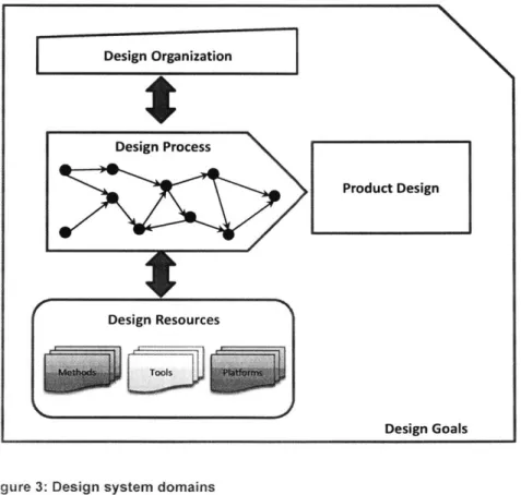
A holistic approach to evaluating legacy design practices for improvement begins with the realization that an entire system is at work during the design of a new aerospace product. As section 2.2 explains, this system - the design system - consists of five domains: the design goals, the product design, the design process, the design organization, and the design resources, as depicted in Figure 3. The design process is the set of tasks undertaken by the design organization to produce the product design. To accomplish this, the design organization utilizes design resources, a domain that includes three elements: design methods, design tools, and design-enabling platforms.
Design Organization
Design Process
Product Design
Design Resources
Design Goals
Figure 3: Design system domains
A design method is the fundamental problem-solving technique used to tackle a design task, while a design tool is a particular implementation of the method that the designer interacts with. If an enterprise is developing a novel aircraft configuration to meet new customer needs, a
MIT SDM Thesis
design tool will be handicapped by an underlying design method that is ill-equipped to deal with the new physics or complexity. A deficient design tool will in turn inhibit the designer who wields it from fulfilling the design task with a deliverable of satisfactory quality or at acceptable cost. A flawed task deliverable can impact downstream tasks and propagate design errors that are
expensive to correct if not discovered early enough.
A design methodology is a set of methods collectively used to execute a design process and form the overall product design. A methodology dominated by inadequate legacy design methods causes the design process to deliver a deficient product design and results in poor quality, cost and schedule outcomes. This assertion is born from a systemic view of design and
its various facets.
MIT SDM Thesis
1.3 Choosing the Right Design Methods
Enormous potential for improving design quality and development project performance is found in a structured approach to design methodology and, in particular, a framework for designers to select which design methods to deploy to solve tasks. The designer always chooses their methods, consciously or unconsciously. Even if the design methodology is openly formulated and not relegated to implicit decisions, many design organizations succumb to the inertia of legacy methods. It is easy to default to the existing methodology without basing that choice on the actual requirements of the design situation in a transparent decision-making process involving all relevant parties of the design team.
What is needed is a framework to support the designer's consideration of a broad range of applicable design methods and selection of methods that meet each unique design context. Method selection decision support that helps the designer cope with and efficiently search and assess the plethora of methods in existence can be accomplished through an attribute-based approach. By rigorously characterizing methods with relevant attributes while accounting for contextual factors, methods can be systematically evaluated for compatibility with design tasks, and the attribute differences of compatible methods can be compared against the needs of the situation to make a selection.
MIT SDM Thesis
1.4 An Illustrative Example
To demonstrate the concept of attribute-based method selection for the development of aerospace products, consider the following flight vehicle control law design task: "Tune the control law design parameter for a particular flight control system feedback loop." The premise of the task is that some control law architecture has already been defined and now a junior,
less-experienced control law engineer has been charged with tuning a specific parameter of that architecture, e.g. a feedback gain, to achieve desired closed-loop vehicle performance. The method selection framework assists the engineer in discovering control law tuning method alternatives and comparing these alternatives prior to a final choice of method to use.
1.4.1 Determining Available Method Options
As described in general in subsection 2.2.3 and section 4.4, the flight control law parameter tuning task can be decomposed into a set of input information (or "design artifacts") transformed
into output information:
Input Artifacts: closed-loop performance criteria, and the control law loop transfer function
* Transformation (or "design activity"): control law parameter tuning, which involves "basic activities" such as simulating, analyzing and adjusting
* Output Artifact: tuned design parameter value
Let the engineer's baseline method be the so-called root-locus method. Using compatibility-relevant method attributes, it is evident that the root-locus method is certainly a fit for the task at hand since it converts the input artifacts of controller performance criteria and loop transfer function information into a tuned design parameter value output artifact by performing the "control law parameter tuning" design activity.
One alternative method that is also compatible with this design task is the frequency-response method. The frequency-frequency-response technique also uses design criteria and the control
MIT SDM Thesis
law loop transfer function to come up with a tuned feedback gain via the "basic activities" of simulating, analyzing and adjusting. Of course, the principles, procedures and mathematical tools employed by the root-locus and frequency-response techniques to analyze dynamical systems are different, but all that is required for both of these methods to be applicable to the same design task is for the methods and task to share the same input artifacts, output artifacts, and basic activities.
1.4.2 Comparing Methods by Their Attributes
As discussed in detail in sections 4.5 and 4.6, several comparison-relevant method attributes can be utilized to determine the pertinent differences between the root-locus and frequency-response methods:
" Method Inputs: The root-locus method typically takes closed-loop performance criteria in the form of desired pole-zero locations, whereas frequency-response design criteria usually involve bandwidth and stability margin (gain margin, phase margin) specifications. If one form is easier to obtain than the other depending on, say, the particular vehicle or product context involved, that may influence the final choice of tuning method.
* Method Outputs: no difference (tuned design parameter value)
* Quality of Method Outputs: The frequency-response method may yield more accurate tuning answers than root-locus, but with lower precision and in a less accessible format (time domain vs. frequency domain) due to control law tuning tool availability and the engineer's experience level and skillset, even for the same time and effort spent on each method and after accounting for some initial frequency-response method training for the user (though more method training may change this attribution). However, the precision and accessibility concerns may not be important if there is an overriding need for
MIT
SDM
Thesis
accuracy due to dependencies of downstream design tasks on this feedback gain tuning task.
* Method Implementation Cost: Switching to the frequency-response method will entail some upfront tool setup and user training costs (e.g. time, labor, software procurement) - not to mention intangible experience building - that staying with root-locus does not involve. However, it may take longer to execute the root-locus technique each time to come up with a tuned feedback gain relative to the frequency-response method, if both methods were held to a given quality level (e.g. accuracy). And root-locus could involve higher "maintenance" costs over the long run to let it work with multi-parameter control loops and to compensate for its lower average accuracy. Nonetheless, the nonrecurring startup costs associated with choosing the frequency-response method may be an overriding concern if there is a strict schedule constraint on this tuning task.
This example illustrates how the use of key attributes to compare candidate methods in multiple dimensions can be readily correlated against governing constraints on the overall design task to efficiently yield a fairly complete understanding of the important tradeoffs involved in picking one method over the other. For this flight control law gain tuning task, the junior engineer may elect to switch from root-locus to the more accurate and lower recurring-cost frequency-response method because performance criteria input information in bandwidth/stability margin format is readily available and the design team, based on the transparent method comparison provided by this framework, decides to budget in sufficient method familiarization time and infrastructure setup to facilitate the transition. Even this relatively simple case demonstrates the complex and multifaceted issues present in these method selection decisions, which up to now have often occurred tacitly without team involvement or holistic considerations.
MIT SDM Thesis
1.5 Thesis Organization
The structure and relationships between the remaining sections of this thesis are depicted in Figure 4. Chapter 2 Literature Survey and Theoretical Framework provides the background and context for the thesis motivation (sections 3.1 and 3.2), and both serve as the foundation for the rest of the work. The research question (3.3) immediately follows from the motivation, and research objectives (3.4) are crafted to answer the research question. A research approach (3.5) is developed to gather data for and address the research objectives. From the thesis
formulation, section 4.1 Conceptual Framework for Method Selection proposes a construct for directing the case study. Section 4.2 Program Overview sets the backdrop for the rest of the case study. The bulk of the development of the case study (sections 4.3, 4.4, 4.5 and 4.6) is in close alignment with the method selection framework, and the case study results are presented in Chapter 5. The contributions of the work (6.1) in achieving the research objectives are summarized, and based on the case study results the research findings (6.2) are reported to answer the research question. Finally, recommendations going forward (6.3) are offered.
MIT SDM Thesis
Recommendations (6.3) Research Findings (6.2) Research Contributions (6.1) Research Approach (3.5) 0E Research U Objectives (3.4) L6
Queso r(3.3) Program Overview (4.2)
Motivation (3.1, 3.2) Literature Survey (2)
Figure 4: Thesis structure
MIT SDM Thesis
2 Literature Survey and Theoretical Framework
A more thorough treatment of the background on this work's field of study is contained in
this chapter: the issue of aerospace product development cost growth and the area of design science research. Summaries of the literature and definitions are given to provide the context and vocabulary for the thesis motivation, formulation, analysis and discussion that follow.
2.1 Aerospace Affordability
2.1.1 Scope of Research Problem
This thesis is concerned with the broad problem area of rising development costs in the U.S. aerospace industry. The situations in question have several common traits:
* Development projects: Systems or technologies are being designed and produced predominantly for the first time. A detailed treatment of the nature of product
development is covered in section 2.2 below.
* Complex systems: As aerospace products are developed to meet increasingly demanding customer requirements, the complexity and scale of the products have grown accordingly.
* Large organizations: Companies and enterprises coordinate multiple groups of people, complicated processes, and vast pools of resources to execute these projects.
* High and mounting costs: The rest of this section expounds on this trait of recent aerospace development project.
It is worth mentioning that even the wide-ranging problem of aerospace development costs has an even broader context: cost is but one of many possible measures of project performance. The classic triple constraint on quality in project management considers scope and schedule in addition to cost. Ulrich and Eppinger (2012, pp. 2-3) lay out five profitability-related measures of a product development project's performance: product quality, product cost, development time, development cost, and development capability. Note the attention paid in this list to production
MIT SDM Thesis
(not just the development period) and to the organization's resulting product development competence (not just that particular project's product). All of these dimensions affect each other; this thesis chooses to highlight cost overruns simply to exemplify the challenges currently facing aerospace system development.
2.1.2 Aerospace Development Cost Trends and Implications
New product development costs - in contrast with unit procurement or flyaway prices - are generally those associated with activities starting from program initiation and ending with delivery of the first operational unit (Eskew, 2000, p. 213). As a general rule of thumb, Ulrich and Eppinger (2012, p. 5) state that product development costs are roughly proportional to the number of people involved and the duration of the project; thus, cost overruns and schedule delays go hand in hand. They use the Boeing 777 as an example of a large-scale development effort on a spectrum of other engineered, discrete products.
The pervading consensus is that U.S. aerospace system development costs are skyrocketing. The overall picture can be painted by a series of sources:
* "The duration and cost of [aerospace and defense] system development efforts... has experienced rapid exponential growth over time" (DARPA, 2009, p. 5).
" "The cost of Defense procurement is on a seemingly ever escalating cycle in the West. In the United States programs are now measured in the hundreds of billions of dollars. Cost increases from initial estimates can rise more than 60%." (Furuhjelm et al., 2017, p.
1)
* "The time required to execute large, government-sponsored systems development programs has more than doubled over the past 30 years, and the cost growth has been at least as great" (Committee on Pre-Milestone A Systems Engineering, 2008, p. 14) * "The set of 96 major weapon system development programs currently underway have
overrun by a total of $296 billion, with an average development cost growth of 42%, and
MIT SDM Thesis
an average delay of 22 months... This is not a new phenomenon, but it appears to be worsening. Current defense system developments, projected to completion, are overrunning 78% in cost and 63% in schedule." (Collopy and Hollingsworth, 2009, p. 1) These rising development program costs are troubling in several ways. In the case of defense systems, resulting schedule delays impact the Warfighter and cost overruns ultimately hurt the taxpayer. Annual aircraft unit cost increases have been found to be greater than inflation indices, which when combined with relatively fixed defense investment budgets -implies fewer aircraft procured over time and forces a drop in government procurement rates and inventories (Arena et al., 2008). Augustine (1986, p. 143) humorously predicted, "In the year 2054, the entire defense budget will purchase just one aircraft. This aircraft will have to be shared by the Air Force and Navy 3-1/2 days each per week except for leap year, when it will be made available to the Marines for the extra day."
For commercial enterprises, cost growth and schedule delays hurt profitability. There is significant incentive to "break the cost curve." As Krishnan (1993, p. 8) notes, "...higher performance companies can reap huge cost benefits by more creative and efficient utilization of resources, smaller work-in-process and reduced development time." A survey of aerospace and defense industry and government sectors reported that more than 40 percent believed the aerospace development project performance problem to be at least as serious as the
2007-2008 housing and banking crises (Deloitte, 2009, p. 1).
2.1.3 Causes of Development Cost Growth
2.1.3.1 General Discussion
When considering what the underlying causes are for the alarming trends in aerospace and defense development costs, DARPA (2009) puts the spotlight on inadequate design practices. While system complexity has increased rapidly by several orders of magnitude, the systems engineering approach and design process applied to develop these systems have remained
MIT SDM Thesis
essentially unchanged. When design organizations fail to cope with growing complexity, project performance inevitably suffers.
A more multifaceted exposition presents five causes of rising development costs: technical complexity, talent shortage, supply chain challenges (e.g. outsourcing, coordination), politics (e.g. perceptions), and program management challenges (e.g. leadership turnover) (Deloitte, 2009). Complexity and, by extension, the systems engineering competence to address it are again called out.
Arena et al. (2008) attribute one-third of military aircraft unit cost increases to "economy-driven" factors (e.g. insufficient competition) and two-thirds to "customer-"economy-driven" factors (e.g. aircraft complexity, procurement program instability). They single out complexity as well -mostly driven by the desire for greater system capabilities, new build aircraft, and engineering change orders - labeling it the biggest single contributor to cost escalation.
Ulrich and Eppinger (2012, p. 6) record several challenges that affect the success of product development: the existence of tradeoffs instead of clear optimums, dynamic and uncertain environments, far-reaching sensitivity to technical details, time pressure, and the need for economic viability. Inadequate design capacity to deal with technical complexity could allow many if not all of these challenges to contribute to rising development costs.
It is important to keep in mind that development costs (and durations) are an emergent property or outcome of the underlying project dynamics. In classic system dynamics applications in project management (Lyneis et al., 2001), normal or initial work (non-rework) accomplishment is distinguished from rework (e.g. errors) and scope growth that drive up total duration and costs. Staff changes (e.g. productivity), management actions (e.g. staffing levels, overtime) and domino effects between projects can drive vicious cycles of declining project performance that obscure the root cause - namely, the introduction of rework due to quality issues such as design errors. At the very least, the recognition of these coupled dynamics at
MIT SDM Thesis
work within the project should motivate the pursuit of "design process improvement" as one prong in a multifaceted approach to addressing the growth of development costs.
2.1.3.2 The Importance of a Good Design
Therefore, it is clear that product design is a key influence on the performance of the overall product development effort. Design determines what system is to be implemented and eventually fielded and operated, and as such it has significant leverage on the total cost to develop the system. The Committee on Pre-Milestone A Systems Engineering (2008, p. 21) states, "...about three-quarters of the total system life cycle costs are influenced by decisions made before the end of the concept refinement phase..." And according to Krishnan (1993, p.
8), "A major fraction of a product's manufacturing costs - anywhere between 60-80% - are
determined at the product design stage and it has been suggested that the decisions made at this stage be of higher quality."
The literature affirms the importance and potential that lies with improving design capabilities in order to manage product complexity and development costs. One form of the argument asserts that manufacturing performance among firms is converging, thus raising pressures to gain competitive differentiation via product design aptitude (Krishnan, 1993, p. 8). Another highlights how globalization and new information and communication technologies are driving shorter product lifecycles and increased product complexity, which requires the adoption of flexible and optimized product development practices (Birkhofer et al., 2002, p. 1).
First-time quality of the system design contributes to less downstream rework and an overall faster and lower cost development cycle. If inadequate design is performed, the product
implementation period will be more costly as test and evaluation reveals design flaws and introduces rework (re-design, re-build, re-test). Even worse, if design flaws are not revealed during testing, any deficiencies relevant to the customer will be exposed after deployment during operational use when it will be even more expensive to correct issues.
MIT SDM Thesis
2.2 Design Research
2.2.1 Design Science and the Product Development Context
Research on design science studies structured approaches to design. The definition from Cross (1993, p. 21) says, "...design science refers to an explicitly organised, rational and wholly systematic approach to design; not just the utilisation of scientific knowledge of artefacts, but design in some sense as a scientific activity itself." Hubka and Eder (1996, p. 73) present a similar definition: "The term Design Science is to be understood as a system of logically related knowledge, which should contain and organize the complete knowledge about and for designing." They propose organizing design science around four types of knowledge based on whether the subject deals with the act of designing or the designed system itself, and whether it takes the form of descriptive statements (theory) or prescriptive statements (practical knowhow). The subject of this thesis is related to design research concerned with understanding and improving the act of designing.
Design is an essential component of the endeavor known as product development. Ulrich and Eppinger (2012, p. 2) define product development as "the set of activities beginning with the perception of a market opportunity and ending in the production, sale, and delivery of a product." Before further exploring the internal structure of product development, it is useful to first recall that product development occurs in the context of the overall lifecycle of the product. Pahl et al.
(2007, p. 3) describe the product lifecycle with several stages: " Needs/goals " Product planning * Design/development * Production/assembly/test * Marketing/sales * Use/consumption/maintenance
MIT SDM Thesis
* Recycling * Disposal
The generic system lifecycle model from INCOSE (2011) has the following stages: * Exploratory Research * Concept " Development * Production * Utilization * Support * Retirement
There are many other models of the generic product lifecycle, including the "generic product development process" by Crawley et al. (2016) (described shortly) that appears to be broad enough to encompass the entire product lifecycle. One way to consolidate these models for an aerospace product is the following set of lifecycle stages:
1. Birth: A product begins with an idea or opportunity, from market needs and/or the goals of the enterprise developing the product.
2. Business Development: During this stage, market and competition analysis occur, as well as business modeling and financial analysis activities that refine the product opportunity that should be pursued.
3. Design: This stage is traditionally broken up into conceptual design, preliminary design,
and detailed design sub-stages. Note that this refers to a stage in the lifecycle, not the product Design function in the organization.
4. Prototyping: During this period, the development of the product is mainly characterized
by fabrication, assembly/integration, and test and evaluation occurring on pre-production
versions of the system.
MIT SDM Thesis
5. Production: Full-scale production of the product can commence once the product design and its implementation are sufficiently mature.
6. Deployment: Sale and delivery of the product to the end user typically initiates after the Production stage (#5) has begun but then continues for as long as there are produced products to deploy.
7. Operation: The product is eventually in the hands of the end user and operating for its intended purpose, while the manufacturer provides support and maintenance services, perhaps long after the Production (#5) and Deployment (#6) stages end.
8. Evolution: Improvements to the original production version of the system can be based on, for example, user feedback after some period of operation and rolled into subsequent production releases.
9. Retirement: The product is eventually removed from general use and disposed of. Figure 5 portrays this lifecycle model using a representation consistent with that of a complex aerospace system - e.g. most of the product's design is accomplished prior to large-scale distribution and operation of the product.
---Birth D
DeveloprttentII
eve Design Prototyping Production---
;
Main Role of Product Development Evolution
Deployment
(Stage durations not necessarily to scale)
Operation Retirement
lime
Figure 5: Notional product lifecycle as context for product development
Product development's place within the overall product lifecycle is also depicted in Figure 5. Note that its primary scope includes not only the Design and Prototyping stages of the product,
MIT SDM Thesis
but also relevant aspects of the Business Development that births the product and the transition to full-rate production.
Product development is traditionally represented as a process - the product development process (PDP), which captures "the terminology, phases, milestones, schedules, and lists of tasks and outputs" of product development (Crawley et al., 2016, p. 184). Ulrich and Eppinger (2012, p. 13) suggest three interpretations of the PDP:
* The PDP initially creates a wide set of alternative product concepts and then narrows the set of alternatives down and provides an increasingly detailed specification of the product until it is ready to be produced.
" The PDP is an information processing system that transforms inputs such as strategic opportunities, corporate objectives, technologies and production capabilities into outputs such as production and sales plans.
* The PDP is a risk management system that identifies, prioritizes and reduces uncertainties and their effects.
They also point out several reasons for having a PDP: quality assurance, coordination between functions, planning to allow for scheduling, a basis for management monitoring, and support of improvements in future development efforts (Ulrich and Eppinger, 2012, pp. 12-13).
Examples of PDPs abound. Pahl et al. (2007, p. 130) propose the following PDP steps:
1. Plan and clarify the task
2. Develop solution principle (conceptual design)
3. Develop the construction structure (embodiment design, part 1)
4. Define the construction structure (embodiment design, part 2)
5. Prepare production and operating documents (detail design)
Crawley et al. (2016, p. 188) organize their relatively wide-ranging "generic PDP" around different categories of product development activities rather than a strict timeline:
1. Conceive: determine what will be built
MIT SDM Thesis
a. Mission
b. Conceptual design
2. Design: define what is to be implemented
a. Preliminary design
b. Detailed design
3. Implement: convert the design into reality
a. Element creation
b. Integration, test, positioning
4. Operate: operate the real system to deliver value
a. Lifecycle support
b. Evolution
The "complex system" version of the generic PDP from Ulrich and Eppinger (2012) uses the
following steps:
1. Planning
2. Concept development
3. System-level design
4. Design and test (multiple subsystems in parallel)
5. Integrate and test
6. Validation and production ramp-up
Cross (2008, p. 207) reproduced the PDP from British Standard (BS) 7000, 'Guide to Managing
Product Design', which is similar to the "generic PDP" from Crawley et al. (2016) in the extent of
its scope:
1. Motivation/Need
a. Trigger
b. Product Planning
c. Feasibility Study
MIT SDM Thesis
2. Creation a. Design
b. Development
c. Production (manufacture, assembly, test)
3. Operation
a. Distribution (packaging, transport, installation, commissioning)
b. Operation (use) 4. Disposal
Before moving on, the distinction between product development and technology development is made. Whereas an enterprises uses product development to create something to sell to external customers, technology development is predominately concerned with creating artifacts that can be utilized by product development within the enterprise or perhaps sold to other enterprises. Technology development leans in a more scientific direction than the aerospace industry's engineering design-oriented notion of product development. While not necessarily of immediate benefit to consumers in and of themselves, technologies are key ingredients in the products that are valuable to consumers. Put another way, there is a difference between flight and manufacturing technology selection (which is under the purview of product development) and flight/manufacturing technology development. This is depicted by Figure 6, which illustrates how several technology development efforts could be ongoing to mature those technologies sufficiently to eventually include them in the development of the product.
MIT SDM Thesis
Flight Tech Dev Processes
Technolog aturation
Technology Pool
Product Development Process
Technolog aturation
Manufacturing Tech Dev Processes
Figure 6: Multiple technology development processes feeding into the product development process
2.2.2 Product Development Projects as Systems: The Design System
Just as there exists the familiar concept of a Production System that consists of all the raw
materials, storage and distribution centers, tooling, assembly rigs, workers, and other elements
responsible for producing the product, it is helpful to regard Product Development itself as a
system of elements working together to develop the product. The Product Development System
includes the PDP but is more than just the PDP; process is only one aspect of product
development.
There is substantial basis for this viewpoint in the literature. Browning et al. (2006, p. 107)
reference the ZOPH model that identifies the product, process, agent (organization,
technologies, resources, methods, tools, etc.), and goal domains that make up any project or
program.
Danilovic and Browning (2007) show the agent domain divided into separate
Organization and Tool domains. Crawley et al. (2016) describe a "global PDP" that moves
beyond the process to consider all of the following attributes of the product, the product design
activity, and the product implementation activity:
MIT SDM Thesis
" Needs " Goals * Function/process methods/flow * Form/tools * Behavior/schedule * Operator/team * Costs
Any project is a system consisting of five domains, and project development projects are no exception. An overview of the project domains and the interactions between them are depicted in Figure 7 in the style of Danilovic and Browning (2007). These domains make up the Product Development System:
* Goals: This domain houses the objectives (e.g. product performance goals, development cost measures, design team capability targets) and constraints (e.g. product price cap, development schedule limits, manufacturing constraints) pertaining to the other domains. * Product: The primary desired outcome of the Product Development System, the product
has at least two versions: the product design (information) and the built product (reality). The Product domain is created by the Process domain.
* Process: The Process domain is interchangeable with the PDP and consists of the series or sequence of transformations and tasks that eventually yield the product. Also, upstream activities in the process define downstream activities. A traditional PDP can be used to structure the Process domain. The Process domain is enabled by the Resources and Organization domains.
* Resources: This domain covers the enablers (tools, equipment, etc.) and controls (policies, standards, etc.) - in IDEFO terminology (Menzel and Mayer, 2006) - that embody the Process domain and are wielded by the Organization domain, such as
MIT SDM Thesis
design methods, manufacturing technology and integration/test assets. Resources are mapped or assigned to elements of the Process. Note that the term 'Tools domain' from Danilovic and Browning (2007) is intentionally not used here, and replaced with the more generic term 'Resources', in order to allow for less confusing subsequent usage of the term 'design tools' (to be defined).
Organization: Those involved in the product development project are organized into teams, groups, etc. by this domain. Members of the Organization are mapped to and perform elements of the Process and they use Resources - indeed, many times groups deem themselves as belonging to a particular segment of the Process and claim certain Resources as their own. This domain considers team skills, functions, work assignments, and staffing levels.
Figure 7: The product development project's interacting domains
Although in principle each domain interacts with every other domain in the project, as shown in Figure 7, in practice some transformations and assignments are more prominent than others, as portrayed in Figure 8 in the style of Danilovic and Browning (2007). In Figure 8, the "generic PDP" from Crawley et al. (2016) is used to decompose the Process domain into Conceive,
MIT SDM Thesis
Design, Implement and Operate sub-domains; the process Conceives and Designs the product design and Implements and Operates the built product. The Organization domain is mapped or "designed" to execute the Process domain. Resources such as design tools and manufacturing equipment are assigned to facilitate the Process. Thus, the PDP is not only decomposable into phases - the traditional understanding of product development - but it also interfaces with the other domains of the Product Development System. Within the Process domain, upstream tasks define the exact form of downstream tasks, as in the case of downstream design work planning, manufacturing process design, supply chain decisions, and integration/test planning.
manufacturing/ sourcing/ integration/test process design downstream design work planning roduct conception, flight technology select
product desig Pro ecs i Project 1
Organization
I
organization designProcess
Built DesignConceive Design Implement Operate
Product
in
design methodology manufacturing technology,
selectio test asset selection
Resources
goal formulationGoals
Figure 8: Product Development System, with primary interactions between domains of product development projects shown and research scope circledRefocusing back on product conception and design (circled in Figure 8 and referred to
collectively as "product design"), it is now evident that there is a product design "cross-section"
that can be viewed across the Product Development System, as depicted in Figure 3. The
product design elements of the Process domain are essentially "cast" to the other domains,
MIT SDM Thesis
~
n
generating a viewpoint of all product design facets of the Product Development System. This product design perspective is not just the "design phase" of the PDP - it includes all the aspects of and interactions between the project development project domains that are geared towards product design activities. This cross-domain "product design subsystem", or simply design system, is subordinate to the overall Product Development System and is comprised of the design Goals, the Product design itself, the design Process, the design Resources, and the design Organization. As shown in Figure 3, there are three types of design Resources in particular that are important to differentiate:
* design methods (discrete problem-solving approaches), * design tools (implementations of methods), and
* design-enabling platforms (generic assets used to build tools).
This design system framework reinforces the point that design is essential to yet distinct within product development. Cross (2008, p. 204) states, "...it is important to realize that 'design' is only a part of a larger process of product planning and development." The PDPs previously described all designate design as a distinct step(s). Design is placed next to Marketing and Manufacturing as three key functions that participate together in product development, where the Design function conducts design of the product itself (as opposed to the Manufacturing function's design of the production system, or other forms of "designing" that take place during product development) (Ulrich and Eppinger, 2012, p. 3). Furthermore, design exists at different levels of product/system abstraction and along various "planes of decomposition" (e.g. Crawley et al. (2016, p. 302)) - high-level total aircraft aerodynamic performance design is different from (though it may be coordinated with) low-level airframe stringer structural design.
The concept of the design system also provides a basis for applying lessons from design science research. If product design in product development is essentially a system, the
implication is that the design system itself can be "designed". This notion is usually referred to as "design process improvement", but the more precise terminology of the design system
MIT SDM Thesis
framework prevents a narrow focus on Process (tasks) by explicitly counting Goals, Resources and Organization as well. Scenarios can be posed to demonstrate instead how "design system improvement" can be reasoned through; for example, from a design Resources standpoint:
* Fixing everything else constant (e.g. design goals, design staff experience level, productivity), what tradeoffs (in terms of project performance measures like cost or duration) exist for various possible design tool configuration choices?
* After selecting the design tools, do you then adjust the design organization? Or the design process? Or should both be adjusted simultaneously? Or should you pick tools simultaneously with formulating the organization and process?
* How can you improve design method/tool integration within the design Resources domain, to alleviate the manual labor burdens of complex system development and control quality? Are more integrated (interconnected, not necessarily "un-modular") methods/tools better than simpler tool connections? How should one decide whether design tools should be unified, federated, or unconnected? What is the right methods "structure" or set of connections between methods?
* Should design method choices always follow the prior establishment of the design process? Or can the design methodology drive the design process in some cases?
2.2.3 Model of Design
2.2.3.1 Defining 'Design'
To explore avenues for applying guidance from design research on the design systems employed by aerospace development projects, it is illuminating to take a step back and recall some common definitions for the general term "design" and some basic models of design. Ulrich (2011, p. 2) states, "Design is conceiving and giving form to artifacts that solve problems." Crawley et al. (2016) would portray design as the transformation of an ambiguous information vector (influences on system architecture) into the precise information vector ("the design")
MIT SDM Thesis
describing the product to be implemented. According to Hubka and Eder (1996, p. 4), "The task of the designing consists of thinking ahead and describing a structure, which appears as (potential) carrier of the desired characteristics (properties, particularly the functions). One can express this statement also in process terms: designing is defined as the transformation of information from the condition of needs, demands, requirements and constraints (including the demanded functions) into the description of a structure which is capable of fulfilling these demands."
Most general models of design address the process of designing. WNynn and Clarkson (2005) use several dimensions to categorize these design models based on whether the model is:
* Stage-based (project lifecycle phases, chronology, morphology) vs. activity-based (iterative problem-solving, cyclical, rework-intensive, day-to-day)
* Problem-oriented vs. solution-oriented
* Abstract (generic), Procedural (specific), or Analytical " Descriptive vs. Prescriptive
* Design-Focused (improve product) vs. Project-Focused (improve design management) Using these dimensions, they recognize patterns among the design models in the literature, such as:
* Stage-based models are usually problem-oriented * Procedural approaches are usually problem-oriented * Abstract approaches are usually activity-based
As an example of a design process model, Cross (2008) presents an "integrative" model with the following stages:
1. Overall problem 2. Sub-problems
MIT SDM Thesis
3. Sub-solutions
4. Overall solution
Wynn and Clarkson (2005) provide several examples of these design process models from the literature that can be used to find patterns in an aerospace system design process:
* Jones's model has three activities that flow in serial order: first analysis, then synthesis, then evaluation. It is an example of an abstract, problem-oriented, activity-based model. * Cross's 1994 model has four serial activities - exploration, generation, evaluation,
communication - with iteration between generation and evaluation. It is also abstract, problem-oriented, and activity-based.
" Darke's model has three serial activities: generator (solution to a subset of design objectives), conjecture (full solution based on generator results), analysis (improvement on full solution). It is an abstract, solution-oriented, activity-based model.
" March's model is an abstract, solution-oriented, activity-based cycle of three activities:
1. Production: abductive reasoning; propose a candidate solution based on available information
2. Deduction: deductive reasoning; apply physical principles to determine the performance of the candidate solution
3. Induction: inductive reasoning; identify possible means of improving the performance
of the current candidate solution
Of course, there are also many domain-specific and enterprise-specific design process models.
In the end, Wynn and Clarkson (2005, p. 35) admit, "Despite the extensive research undertaken since the 1950s, there is no single model which is agreed to provide a satisfactory description of the design process."
Now, the design system framework (referring back to Figure 3 and subsection 2.2.2) reveals that product design is comprised of the design aspects of the domains that make up the product
MIT SDM Thesis
development project. However, each of the design system domains presents different opportunities for improvement:
* Design Goals: usually predetermined by the development program
* Product design: this is the deliverable of the design system to be ultimately improved * Design Process: With many variations and debates on how to improve the design
Process proper (e.g. see Krishnan (1993), Eppinger et al. (1989), Unger (2003)), the way forward on Process domain improvement is many ways clearer than that for design Resources; nonetheless, it is important to model the design Process when pursuing design system improvement.
" Design Resources:
o Methodology: this thesis explores significant opportunities here
o Toolset: the value of a design tool is driven by the value of its underlying design method
o Design-Enabling Platforms: frequently more adeptly handled by the software/hardware developers
* Design Organization: much existing discussion on how to improve this as well
2.2.3.2 Design Process
Again, it is usually important to model the particulars of the design Process at hand during a design system project improvement effort because the design Process is the main mechanism
by which design Resources and the design Organization affect the product design. The design
process can be modeled as a network of objects and transformations on those objects, not dissimilarly to Object-Process Methodology:
* Design Artifact: This is information (an object) about or leading to the product design that can be converted from or into other artifacts, usually denoted by a noun. Example
artifacts:
MIT SDM Thesis
o Customer brief o Market data
o Solution concept description o Concept analysis results
* Design Activity: This is a transformation or conversion experienced by an artifact, usually denoted by a verb. Example activities:
o Interpreting o Collecting o Synthesizing o Analyzing
* Design Task: This is a particular transformation of information - the combination of a design activity with its corresponding input and output design artifacts. One finds that common text labels or descriptions for tasks are frequently unable to capture all of the inputs and outputs involved in a task. Example task labels:
o Interpret customer brief o Collect market data
o Synthesize solution concept o Analyze solution concept
Hence, the design Process consists of design artifacts and design activities combined to form tasks. Figure 9 illustrates a notional design process using the defined syntax, including complete task descriptions (in graphical, not text, form). Note that multiple tasks could interact with the same artifact (e.g. both tasks 2 and 3 contribute to outputting artifact 6 while task 4 uses artifact 6 as an input), but each task has only one activity. Artifacts from external sources that are not created by any activity in the design process are known as exogenous inputs, such as Artifacts 1, 2 and 4 in Figure 9.