READ THESE TERMS AND CONDITIONS CAREFULLY BEFORE USING THIS WEBSITE. https://nrc-publications.canada.ca/eng/copyright
Vous avez des questions? Nous pouvons vous aider. Pour communiquer directement avec un auteur, consultez la première page de la revue dans laquelle son article a été publié afin de trouver ses coordonnées. Si vous n’arrivez pas à les repérer, communiquez avec nous à [email protected].
Questions? Contact the NRC Publications Archive team at
[email protected]. If you wish to email the authors directly, please see the first page of the publication for their contact information.
NRC Publications Archive
Archives des publications du CNRC
This publication could be one of several versions: author’s original, accepted manuscript or the publisher’s version. / La version de cette publication peut être l’une des suivantes : la version prépublication de l’auteur, la version acceptée du manuscrit ou la version de l’éditeur.
Access and use of this website and the material on it are subject to the Terms and Conditions set forth at
Robust Corner Tracking for Real-Time Augmented Reality
Malik, S.; Roth, Gerhard; McDonald, C.
https://publications-cnrc.canada.ca/fra/droits
L’accès à ce site Web et l’utilisation de son contenu sont assujettis aux conditions présentées dans le site LISEZ CES CONDITIONS ATTENTIVEMENT AVANT D’UTILISER CE SITE WEB.
NRC Publications Record / Notice d'Archives des publications de CNRC:
https://nrc-publications.canada.ca/eng/view/object/?id=a720ec20-3b6a-4863-b657-dd5264684380 https://publications-cnrc.canada.ca/fra/voir/objet/?id=a720ec20-3b6a-4863-b657-dd5264684380
National Research Council Canada Institute for Information Technology Conseil national de recherches Canada Institut de technologie de l'information
Robust Corner Tracking for Real-Time Augmented
Reality *
Malik, S., Roth, G., McDonald, C.
May 2002
* published in Vision Interface 2002. pp. 399-406. Calgary, Alberta, Canada. May 2002. NRC 45860.
Copyright 2002 by
National Research Council of Canada
Permission is granted to quote short excerpts and to reproduce figures and tables from this report, provided that the source of such material is fully acknowledged.
Robust 2D Tracking for Real-Time Augmented Reality
Shahzad Malik
1, Gerhard Roth
2, Chris McDonald
11
School of Computer Science, Carleton University, Ottawa, Canada, K1S 5B6
2
Computational Video Group, IIT, National Research Council, Ottawa, Canada, K1A 0R6
http://www.cv.iit.nrc.ca/research/ar
Abstract
Vision-based registration techniques for augmented reality systems have been the subject of intensive research recently due to their potential to accurately align virtual objects with the real world. The downfall of these vision-based approaches, however, is their high computational cost and lack of robustness.
This paper describes the implementation of a fast, but accurate, vision-based corner tracker that forms the basis of a pattern-based augmented reality system. The tracker predicts corner positions by computing a homography between known corner positions on a planar pattern and potential planar regions in a video sequence. Local search windows are then placed around these predicted locations in order to find the actual subpixel corner positions. Experimental results show the robustness of the corner tracking system with respect to occlusion, scale, orientation, and lighting.
Keywords: Corner tracking, pattern tracking, blob finding, robust, computer vision, augmented reality.
1 Introduction
Unlike virtual reality, which encompasses a user in a completely computer-generated environment, augmented reality is a technology that attempts to enhance a user’s view of the real environment by adding virtual objects, such as text, 2D images, or 3D models, to the display in a realistic manner.
Clearly, the realism that a user will experience in an augmented reality environment is directly related to the stability of the registration between the virtual and real-world objects; if the virtual objects shift or jitter, the effectiveness of the augmentation is lost.
Vision-based augmented reality systems rely on extremely accurate optical trackers in order to obtain the required registration stability. Additionally, these accurate trackers must operate in real-time.
One of the most promising vision-based augmented reality techniques involves tracking a planar pattern in real-time and then augmenting virtual objects on top of the pattern
based on its pose. In [5, 7, 9, 10, 14], black and white planar patterns are tracked resulting in relatively stable registrations, but the tracking algorithms fail to provide any robustness to partial pattern occlusions. Specially arranged coloured blobs are tracked in [8] that can handle partial occlusions for a brief period of time via Kalman filtering, but the blob centroids are less reliable at different scales or plane orientations. Other techniques address robustness and occlusion, but only in hybrid configurations involving expensive magnetic or inertial trackers and stereo configurations [1, 2, 12].
In this paper we describe the implementation of an optical corner tracker for an augmented reality system that is precise, fast, and robust, and which can be implemented using a standard, consumer-level camera and PC. In Section 2 planar homographies are first reviewed since they form the mathematical core of the 2D tracker. Section 3 then provides a description of a fast and reliable region detector that allows the system to self-identify predetermined planar patterns consisting of black and white corners. Section 3.2 then proposes an accurate corner tracker which uses a robustly computed homography to predict corner positions that are then refined using localized search windows. Experimental results are then presented in Section 4, which show the tracker’s stability and robustness to occlusion, scale, orientation, and lighting changes. Additionally, a comparison between corner tracking and commonly used blob tracking techniques is made.
2 Planar Homographies
Tracking planar patterns are advantageous since they define a convenient world coordinate space that can be used for augmentations (Figure 1).
Since we will be tracking such planar patterns, we can make the assumption that they are located on the Z=0 plane in world (pattern) coordinates. Thus we can associate our original pattern with the viewed pattern in a video frame by a 2D-to-2D projective warp. In other words, if x = (x, y, 1) is a homogeneous coordinate in pattern space, and x΄ = (x’,
y’, 1) is the associated coordinate in image space, x ↔ x΄ defines a correspondence that is related by
=
1
1
'
'
y
x
H
y
x
where the 3x3 matrix H is a planar homography. This gives us
x’ (h31x + h32y + h33) = h11x + h12y +h13
y’ (h31x + h32y + h33) = h21x + h22y +h23 where hij is the i,j-th element of H.
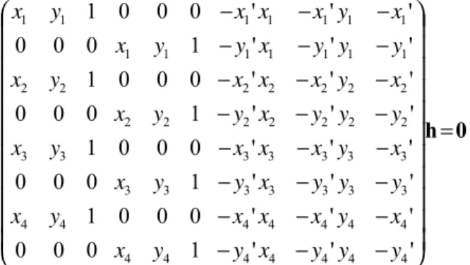
Given at least four such correspondences, we obtain a system of eight linear equations that can be used to solve for the elements of H:
0
h
=
−
−
−
−
−
−
−
−
−
−
−
−
−
−
−
−
−
−
−
−
−
−
−
−
'
'
'
1
0
0
0
'
'
'
0
0
0
1
'
'
'
1
0
0
0
'
'
'
0
0
0
1
'
'
'
1
0
0
0
'
'
'
0
0
0
1
'
'
'
1
0
0
0
'
'
'
0
0
0
1
4 4 4 4 4 4 4 4 4 4 4 4 4 4 3 3 3 3 3 3 3 3 3 3 3 3 3 3 2 2 2 2 2 2 2 2 2 2 2 2 2 2 1 1 1 1 1 1 1 1 1 1 1 1 1 1y
y
y
x
y
y
x
x
y
x
x
x
y
x
y
y
y
x
y
y
x
x
y
x
x
x
y
x
y
y
y
x
y
y
x
x
y
x
x
x
y
x
y
y
y
x
y
y
x
x
y
x
x
x
y
x
where h is a 9-element vector containing the hij elements in
the form h = [h11 h12 h13 h21 h22 h23 h31 h32 h33]T.
Since this matrix equation is in the form of Ah=0, the solution is the null space of A and can thus be computed using known methods, such as singular value decomposition [13].
The next section outlines how the proposed system makes use of such homographies in order to track known planar patterns in video sequences.
Figure 1 – World space defined by a planar pattern
3 System Outline
In our 2D tracker, planar patterns are identified in a live video stream, and predetermined corner features for the detected pattern are found within each frame of video and
tracked in real-time. Figure 2 shows some example patterns.
Figure 2 – Example of 2D planar patterns used for augmentations.
Patterns consist of a thick black border, inside which white rectangles are evenly distributed. The corners of the white rectangles are stored in a data file that is associated with the pattern upon system startup. Although no strict arrangement of rectangles is enforced, it is important to generate patterns that are uniquely identifiable with respect to other existing patterns, as well as under 90 degree rotations. Black and white patterns are preferred over colour due to their high contrast, which is important for region detection and extraction purposes.
The following sections cover the 2D tracker in more detail. There are two modes of operation for the tracker: Search
Mode, and Tracking Mode.
3.1 Search Mode
Before known individual corner features can be tracked from frame to frame, the system must first uniquely identify any valid pattern(s) within the video frame. This is known as Search Mode, and is the initial state of the augmentation system. Using a method similar to [10], the search proceeds as follows:
! Threshold the frame into a binary image. Dynamic thresholding provides the best results, but static threshold values are also sufficient in known environments.
! Find connected regions of black pixels and only accept regions whose bounding boxes meet size and aspect ratio thresholds of our known black-bordered patterns (in order to reject invalid regions).
! Find the four strongest black corner pixels of the connected region and generate a polygon consisting of these vertices in clockwise order.
! Compute a homography from the known boundaries of the original pattern to the polygon corners.
! Using this homography, create a new image consisting of unwarped pixels from the video frame.
World (pattern) coordinates
Camera coordinates Image coordinates
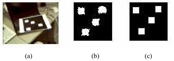
! Find the best matching pattern by comparing the unwarped image with images of the known patterns (via simple binary image subtraction).
Figure 3 shows an example of unwarping the pixels within a connected region, and finding the best matching original pattern. Note that four homographies must be computed for each region, followed by four image comparisons, since there are four potential orientations of the original pattern. As mentioned earlier, the orientation of the original pattern should be unambiguous when viewed at 90, 180, and 270 degrees.
Figure 3 – (a) Captured video frame, (b) unwarped region from video, (c) best matching known pattern.
Once we have successfully identified a valid region and its associated pattern, we are ready to begin local tracking of the individual corner features.
3.2 Tracking Mode
Tracking Mode consists of the following three steps:
Corner Prediction, Corner Detection, and Homography
Refinement.
3.2.1
Corner Prediction
Based on the homography computed in the previous frame, we transform all known corner positions for the detected pattern from world space into the current image space. Each of the transformed positions defines a predicted corner location, but these are not always exact due to inaccuracies in the homography. Therefore a local search window is placed around the predicted corner location, and the actual corner must be in this window.
Assuming temporal coherency, the search window for each corner is also translated by an amount equal to any motion that corner experienced in the previous two frames. The search box size represents how much pixel movement the tracker can tolerate from frame to frame, assuming smooth motion. Increasing the search box allows for more movement, but increases the chances of multiple corners being found in the search box (as discussed in the next section). Conversely, decreasing the search box size reduces the chance of multiple corners, but increases the
chance of tracker failure due to rapid motion of the pattern. Our system works well with 9x9 boxes on normalized 320x240 images, with the overall augmentation system operating at 20 Hz.
3.2.2
Corner Detection
To find the actual corner locations with subpixel accuracy, we do the following for each predicted corner location: ! Apply a Harris corner finder [6] with subpixel accuracy
on the local search window (see Appendix A). An approximation to the Harris corner finder, as presented in [3], can be used which increases performance due to the removal of a square root operation for each pixel location in the search window.
! Extract the strongest corner within the subwindow to determine the actual corner position that corresponds to the original corner from the pattern. If no corner is detected, mark the corner’s tracking status as having failed for this frame. This could occur due to the corner being off the edge of the screen or temporarily
occluded.
Note that at far distances, the subwindow may overlap more than one corner feature from the original pattern (as depicted in Figure 4). Extracting only the strongest corner from the Harris corner finder would thus cause different pattern corners to incorrectly correspond to the same image location. In this case, choosing the closest corner to the predicted location is a slightly better heuristic. For optimal results, neighbouring corner positions and edge properties from the original pattern should be taken into account to determine the best corner location, as outlined in [4].
Figure 4 – Multiple potential corners in a single predicted search window.
3.2.3
Updating the Homography
Using the set of subpixel corner locations found in the current frame, a new set of corner correspondences, {x ↔
x΄}, from the original pattern into image space is computed.
Using the well-known RANSAC approach as outlined in [11], a new homography is determined as follows:
! Randomly sample four non-collinear x ↔ x΄ correspondences.
! Compute H using this sample.
! For all correspondences, compute the distance between
x΄ and Hx.
! Count the number of pairs for which the distance is below some threshold. A value between 2.0 and 4.0 works well for our system.
! Store the H which has the highest number of inliers IH. ! Refit the homography H using these inliers.
The motivation behind random sampling is to remove inaccurate or mismatched corner locations from the homography computation. This allows the homography to be robust to partially occluded features, which is important for subsequent corner predictions.
The number of random samples is capped at the maximum number of known corners Imax for the detected pattern. Most of our patterns consist of four to eight white rectangles, resulting in 16 to 32 corners. In order to reduce the number of samples, however, a threshold is set which allows random sampling to stop if the highest number of inliers IH is above the following threshold
max Q
H
T
I
I
≥
×
where TQ defines a quality measure between 0 (low) and 1 (high). A value above 0.75 seems to provide relatively stable homographies.
The best homography computed after random sampling is then used as the corner predictor in the next frame. Note that random sampling can also fail under the following instances:
! There are less than 4 non-collinear x ↔ x΄ correspondences.
! The best computed H fails to meet our TQ criteria ! IH falls below 4, which is the minimum number of
correspondences required for computing H in the next frame.
In such cases, the tracking system reports tracker failure and reverts back to Search Mode.
The basic idea behind refining the homography via random sampling is to increase the robustness of the pattern tracker. With multiple corners being tracked simultaneously, occlusions of a subset of the feature points should have little or no effect on the corner prediction in the next frame. For example, if a detected pattern consisting of 24 corners is being tracked, the homography should still be able to predict corner positions for the next frame even if approximately 16 corners are currently occluded by a user’s hand. The assumption is that the other 8 corners interspersed around the pattern area are sufficient to
accurately determine the pattern’s current orientation. In fact, 4 unoccluded, non-collinear corners are all that is necessary. The predicted locations for the occluded corners will still be searched in upcoming frames so as soon as the occlusion stops (i.e. the user’s hand is removed from the pattern) all 24 corners will be detected again.
3.3 Tracker Summary
Figure 5 outlines the basic operation of the 2D tracking system.
Figure 5 – Block diagram of the augmentation system
Upon initialization, the system is in Search Mode and is continuously attempting to find a known planar pattern in each frame of video. Once a valid pattern is detected, a homography is computed from the four corners of the original pattern and the detected four corners of the region in the video. The system then enters Tracking Mode, which uses the previous homography to predict the locations of the corner features for the pattern. These corners are then used to compute a new homography for the next frame, even if the pattern is experiencing significant occlusion. Upon tracking failure, the system returns to Search Mode, which attempts to recover the entire pattern again for further tracking.
MPEG videos of the tracking process can be found on our web site. The software itself can also be downloaded from this page, along with the patterns to enable anyone to test the operation of the tracking and augmentation system.
4 Results and Discussion
4.1 Performance
One of the major design goals of our augmented reality system is real-time performance on standard PCs using off the shelf USB camera hardware. The current implementation of our tracking system uses OpenGL to augment simple 2D textures and 3D objects onto the planar patterns at 20Hz on an Intel Pentium 3 800MHz PC equipped with an ATI Rage128 Video card and an Intel CS110 USB camera. Augmentations are currently displayed on a desktop monitor, but for immersive applications we will eventually attach the camera to a head-mounted display.
In order to obtain an accurate estimate of the Search Mode time, we modified the implementation to always remain in
Search Mode and use the computed homography to augment 2D polygons onto the pattern.
The current breakdown of average processing time per frame when viewing a static planar pattern consisting of 24 corners is as follows:
Search Mode: 29.1ms Tracking Mode: 10.7ms Augmentation Time: 2.1ms
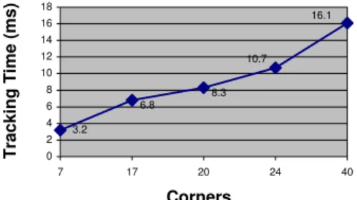
Clearly, the global search method is significantly slower than tracking 24 localized corner features. However, the system is usually in Tracking Mode so performance is directly related to the number of corners being tracked; the more corners we have, the longer it takes for the tracker to operate. Figure 6 shows tracking times for a set of patterns with varying corner counts. As can be seen, processing time increases approximately linearly with respect to the number of corners that need to be tracked.
3.2 10.7 8.3 6.8 16.1 0 2 4 6 8 10 12 14 16 18 7 17 20 24 40 Corners T racki ng T im e (m s)
Figure 6 – Corner Tracking Performance
4.2 Tracking Accuracy
The stability and accuracy of the homography is directly related to the stability and accuracy of the augmented
objects. In other words, if the homography cannot accurately recreate the orientation of the pattern in screen space, then the pose computations will be similarly affected. In order to test the stability of the system, all original pattern corners x are transformed by H, and the distance between the computed position Hx and the detected position x΄ is determined. The average of these distances over all correspondences is the average reprojection error REavg, represented mathematically as
N
H
'
RE
N i i i avg∑
=−
=
0x
x
where N is the total number of corner correspondences. Our current implementation exhibits an average reprojection error between 0.8 and 1.4 pixels with various patterns (all corners being tracked successfully), which is quite good for our normalized 320x240 images and a standard USB camera. Scale and orientation of the pattern have no apparent effect on the error, provided all corners continue to be tracked successfully. As soon as some corners become occluded, however, the reprojection error begins to increase.
4.2.1
Occlusion Handling
One of the main advantages of our tracking approach is the ability to handle significant amounts of occlusion. Figure 7 shows a 17 corner pattern experiencing approximately 30% occlusion. The tracker can still detect enough corners so that a virtual 2D image can be correctly augmented onto the plane.
Figure 7 – Successful augmentation onto a partially occluded pattern
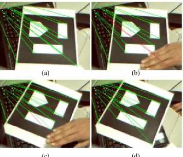
Even under motion, the prediction scheme allows corners to be correctly recovered after temporary occlusions. Figure 8a shows a pattern with all of its 17 corners being tracked successfully (indicated by green lines). Figure 8b then shows a hand occluding two of the corners, with red lines denoting the predicted locations. While occluded, the pattern is rotated slightly such that one of the occluded corners becomes visible again. The non-occluded corner is then recovered, as depicted in Figure 8c. Note that the other corner is still being occluded, but the predicted
location has changed after rotation. After removing the hand from the scene, the predicted location for the remaining corner allows it to be recovered, as depicted in Figure 8d.
One interesting observation was the gradual decrease in the stability of the homography as more corners become occluded. Predicted locations for corners begin to jitter significantly when the corner counts fall below 10 or so.
Figure 8 – Corner recovery from occlusion after pattern motion
4.2.2
Effects of Scale
The major advantage in using corners for tracking is that corners are invariant to scale. The corner tracker can thus continue to track patterns at a large range of distances from the camera. This is where a tradeoff must be considered between allowable viewing distances and allowable motion. To allow viewing at large distances, the search box should be small to reduce the chance of multiple corner detection. However, this affects the ability to track fast movements of the pattern when viewed close-up. On the other hand, if the search box size is set too large, significant motion is allowed from frame to frame but the corner finder will fail when viewing the pattern further away.
One possible approach to solving this problem is computing a dynamic search box size which changes based on a pattern’s distance from the camera. If the pattern is determined to be far from the viewer, reduce the search box size under the assumption that 1) significant motion of the pattern has a smaller effect in screen space, and 2) corners in the pattern will be closer together. If the pattern is found to be close to the camera, increase the search box size since
the chance of multiple corner detections is low and pattern motion has more effect in screen space.
Currently, patterns must be visible in at least 25% of the view, with no occlusions, in order for Search Mode to lock onto the pattern. This can be adjusted based on size and aspect ratio thresholds. Once the system proceeds into
Tracking Mode, the pattern is still able to be tracked when it occupies between 10% and 150% of the video image on average, depending on the number and distribution of the corner features.
4.2.3
Effects of Orientation
Due to perspective distortion, a square on the original pattern does not necessarily remain square when viewed at a sharp angle and projected into image space. Thus, corners will change their shape which affects the corner finder’s detection ability. However, this is not a problem since the Harris corner detector relies on finding intensity changes in two directions, which are still evident even at severe orientations [13].
Figure 9 – Tracking under severe rotation
The major source of orientation problems is once again the search box size. It plays a key role since corner features on a planar region begin to converge onto other corners in screen space. For example, Figure 9 shows a 24-corner pattern undergoing a gradual rotation of 90 degrees. As can be seen, the corner detection begins to deteriorate since corners are beginning to enter search boxes for other corners. As expected, the average reprojection error of the homography begins to increase as more corners begin to converge. However, as Figure 9 shows, the tracking continues up to almost 75-80 degrees, which is quite robust for many types of augmentations.
(a) (b)
(a) (b) (c) (d)
4.2.4
Variable Lighting Conditions
Another favourable property of the corner feature for tracking purposes is its robustness to lighting. Since intensity changes in two directions form the basis of corner finding, no special considerations need to be taken into account from the tracker’s perspective in order to handle significant lighting changes or shadows. Therefore, as long as the black and white features on the planar pattern are somewhat distinguishable, the corner tracker continues to compute an accurate homography, even under dramatic changes in lighting.
4.3 Comparison to blob trackers
The homography-based tracking approach described in this paper could work with black and white blob features on planar patterns just as it does with corners. However, we have found corners superior to blobs due to their occlusion, scale, orientation, and lighting advantages.
Up till now, blob-based trackers were the most popular tracking primitive for vision-based augmented reality systems. Therefore we conducted a set of experiments aimed at comparing blob trackers with the corner tracking system.
4.3.1
Blob Performance
The most obvious reason for using blobs over corners involves performance. Detecting corners has traditionally been considered an expensive operation, while blob finding algorithms are known to be very fast since they primarily deal with finding connected regions of similar pixels. By replacing the “Corner Detection” component of Tracking
Mode with a “Blob Detection” system (Figure 5), the overall tracking time should theoretically be reduced. Implementation results, however, showed no significant changes in tracking time. This is largely due to the larger search box requirement of blobs, since blobs are typically larger than the 9x9 window used for corners.
4.3.2
Blob Occlusion
Figure 10 shows a finger partially occluding a blob. As a result, the centroid location for the occluded blob will become offset from its correct location. If the foreground pixels are added to the search area of the occluded blob, then the blob’s pixel set is the union of occluding object pixels and actual blob pixels. On the other hand, if the occluding object adds background pixels to the blob when overlapping it, the blob’s pixel set will fail to contain all pixels that are needed to properly represent the blob (as in Figure 10). In each instance, the blob’s position, size, and orientation computation has significant error. A blob-based tracker that handles partial occlusions by using two-colour
blobs (an inner blob surrounded by a different coloured outer ring) is described in [12]. This allows the system to more uniquely detect blobs in a scene, as well as predict the entire blob shape when it is partially occluded (assuming the two colours are partially visible). The disadvantage with this approach is the fact that colour image thresholding must be used, which is prone to errors.
4.3.3
Blob Scale
As the camera’s distance from a blob increases, the blob’s pixel set decreases. Thus, the same blob has less representation in pixel space leaving less accuracy for characteristics such as position, shape and relative size in the image. At greater distances the pixel set can even be empty, leaving no traceable feature. Corners, on the other hand, are robust to scale as discussed in Section 4.2.2 (the search box issues are a separate matter that would also be apparent in a blob-based tracking scheme.)
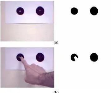
Figure 10 – Blob detection and centroid location (left image is original video frame, right image is after binary thresholding): (a) no occlusion, (b) partial occlusion has shifted the centroid (the white crosshair)
4.3.4
Blob Orientation
Similarly, orientation of the camera also degrades a blob’s pixel set by reducing the representation of the blob in the image compared to that in real space. Additionally, for large blobs being viewed at close range, the computed centroid position does not take perspective distortion into account. Thus the actual centre of a blob in world space and the corresponding blob centre in image space may not necessarily correspond. This would affect relative blob positions on a planar pattern, resulting in inaccuracies in homography computation.
(a)
4.3.5
Blob Lighting
Since blob detection typically involves thresholding each frame into a binary image, a blob-tracker would thus have to implement a dynamic thresholding scheme similar to what is required for our tracker’s Search Mode. The simplest approach involves computing a histogram for a grayscale representation of the video frame, and choosing the threshold to be at the local minimum between the two peaks of the histogram. While this approach works well, it is not as convenient as the automatic light and shadow handling exhibited by a robust corner detector.
5 Conclusion
In this paper we described a robust solution for vision-based augmented reality tracking that identifies and tracks, in real-time, known planar patterns made up of corners. The major advantages of tracking corners are their detection robustness at a large range of distances, their reliability under severe planar orientations, and their tolerance of lighting changes or shadows. An overview of the tracking system was described, and experiments demonstrated the feasibility and reliability of the system under various situations, most significantly under partial pattern occlusion. Additionally, a comparison between corner-based tracking and blob-based tracking was made.
References
[1] Thomas Auer, Axel Pinz. “The Integration of Optical and Magnetic Tracking for Multi-User Augmented Reality”. Computer & Graphics 23, 1999. pp 805-808.
[2] Azuma, R., Neumann, U., You, S. “Hybrid Inertial and Vision Tracking for Augmented Reality Registration”. 1999
[3] A. Benedetti, P. Perona. “Real-time 2D Feature Detection on a Reconfigurable Computer”. Proceedings of the IEEE Conference on Computer Vision and Pattern Recognition, 1998.
[4] Stefan Brantner, Thomas Auer, Axel Pinz. “Real-Time Optical Edge and Corner Tracking at Subpixel Accuracy”. Proceedings of 8th International Conference on Computer
Analysis of Images and Patterns CAIP ’99. Springer, F. Solina, A. Leonardis (eds.), 1999. pp. 534-541.
[5] Mark Billinghurst, Hirokazu Kato, Ivan Poupyrev. “The MagicBook: A Transitional AR Interface”. Computer &
Graphics. Issue 25, 2001. pp. 745-753.
[6] C. Harris, M. Stephens. “A Combined Corner and Edge Detector”. In Alvey Vision Conf, 1998. pp. 147-151.
[7] Hirokazu Kato, Mark Billinghurst. “Marker Tracking and HMD Calibration for a Video-based Augmented Reality Conferencing System”. Proceedings of 2nd IEEE and ACM International Workshop on Augmented Reality IWAR ‘99, 1999. pp. 85 -94.
[8] Jose Molineros, Rajeev Sharma. “Real-Time Tracking of Multiple Objects Using Fiducials for Augmented Reality”. Real-Time Imaging 7, 2001. pp. 495-506.
[9] Ivan Poupyrev, Desney Tan, Mark Billinghurst, Hirokazu Kato, Holger Regenbrecht, Nobuji Tetsutani. “Developing a Generic Augmented-Reality Interface”. IEEE Computer, March 2002. pp 44-50.
[10] Jun Rekimoto. “Matrix: A Realtime Object Identification and Registration Method for Augmented Reality”.
Proceedings of Computer Human Interaction. 3rd Asia Pacific. pp. 63-68.
[11] Gilles Simon, Andrew Fitzgibbon, Andrew Zisserman. “Markerless Tracking using Planar Structures in the Scene”. Proceedings. IEEE and ACM International Symposium on Augmented Reality ISAR 2000, 2000. pp 120-128.
[12] A. State, G. Hirota, D. Chen, W. Garrett, M. Livingston. “Superior Augmented Reality Registration by Integrating Landmark Tracking and Magnetic Tracking”. http://www.cs.unc.edu/~us/hybrid.html
[13] Emanuele Trucco, Alessandro Verri. Introductory
Techniques for 3D Computer Vision. Prentice-Hall, 1998. [14] James R. Vallino. Interactive Augmented Reality. PhD
Thesis, University of Rochester, Rochester, NY. November 1998.
[15] Andrew Zisserman. “Geometric Framework for Vision I: Single View and Two-View Geometry”. Lecture Notes, Robotics Research Group, University of Oxford.
A. Subpixel Corner Detection
The corner finder computes a corner strength value λ for each pixel p in a search window, where λ represents the smaller of the two eigenvalues for a neighbourhood of pixels around p. Non-maximal suppression is used to locate the strongest corner position s = (x, y) in this neighbourhood, but a subpixel location can be computed based on weighting the corner strengths of the 4-connected neighbours
where λi represents the corner strength of pixel i in Figure
11. ) λ λ 2 λ ( 2 ) λ λ ( 5 . 0 _ a s b b a x x sub + − − + + = ) λ λ 2 λ ( 2 ) λ λ ( 5 . 0 _ c s d d c y y sub + − − + + = Figure 11