READ THESE TERMS AND CONDITIONS CAREFULLY BEFORE USING THIS WEBSITE.
https://nrc-publications.canada.ca/eng/copyright
Vous avez des questions? Nous pouvons vous aider. Pour communiquer directement avec un auteur, consultez la première page de la revue dans laquelle son article a été publié afin de trouver ses coordonnées. Si vous n’arrivez pas à les repérer, communiquez avec nous à PublicationsArchive-ArchivesPublications@nrc-cnrc.gc.ca.
Questions? Contact the NRC Publications Archive team at
PublicationsArchive-ArchivesPublications@nrc-cnrc.gc.ca. If you wish to email the authors directly, please see the first page of the publication for their contact information.
NRC Publications Archive
Archives des publications du CNRC
This publication could be one of several versions: author’s original, accepted manuscript or the publisher’s version. / La version de cette publication peut être l’une des suivantes : la version prépublication de l’auteur, la version acceptée du manuscrit ou la version de l’éditeur.
Access and use of this website and the material on it are subject to the Terms and Conditions set forth at
Long-term thermal resistance of polyisocyanurate foam insulation with impermeable facers
Mukhopadhyaya, P.; Bomberg, M. T.; Kumaran, M. K.; Drouin, M.; Lackey, J. C.; Van Reenen, D.; Normandin, N.
https://publications-cnrc.canada.ca/fra/droits
L’accès à ce site Web et l’utilisation de son contenu sont assujettis aux conditions présentées dans le site LISEZ CES CONDITIONS ATTENTIVEMENT AVANT D’UTILISER CE SITE WEB.
NRC Publications Record / Notice d'Archives des publications de CNRC: https://nrc-publications.canada.ca/eng/view/object/?id=0ffe7e40-b010-4795-a9de-8664342c495f https://publications-cnrc.canada.ca/fra/voir/objet/?id=0ffe7e40-b010-4795-a9de-8664342c495f
Long-term thermal resistance of polyisocyanurate foam insulation with impermeable facers
Mukhopadhyaya, P.; Bomberg, M.T.; Kumaran, M.K.; Drouin, M.; Lackey, J.; van Reenen, D.; Normandin, N.
A version of this document is published in / Une version de ce document se trouve dans :
Insulation Materials: Testing and Applications: 4th Volume, ASTM STP 1426, pp. 351-365
www.nrc.ca/irc/ircpubs
Phalguni Mukhopadhyaya,1 Mark T. Bomberg,2 M. Kumar Kumaran,3 Michel Drouin,4 John Lackey,5 David van Reenen,5 and Nicole Normandin5
Long-Term Thermal Resistance of Polyisocyanurate Foam Insulation with Impermeable Facers
Reference: Mukhopadhyaya, P., Bomberg, M. T., Kumaran, M. K., Drouin, M., Lackey, J., van Reenen, D., and Normandin, N., 'Long-Term Thermal Resistance of Polyisocyanurate Foam Insulation with Impermeable Facers,' Insulation Materials:
Testing and Applications: 4th Volume, ASTM STP 1426, A. O. Desjarlais, Ed., American
Society for Testing and Materials, West Conshohocken, PA, 2002.
Abstract: Polyisocyanurate (polyiso) foam insulation with impermeable facers is known for its superior insulating properties in building envelope applications. The impermeable facer on both sides of polyiso foam insulation board is designed to increase and maintain the long-term thermal resistance (LTTR) of the insulation. Currently, the Institute for Research in Construction (IRC)/National Research Council (NRC) of Canada, in association with the Canadian Polyisocyanurate Council, has embarked on a research project to develop a standard test methodology that would help to quantify the design LTTR value of polyiso foam insulation boards with impermeable facers. This paper outlines the research project and presents preliminary test results from experimental work. These preliminary results are discussed with a view to developing a methodology that will be used as the basis for a National Standard in Canada for the determination of LTTR of polyiso foam insulation with impermeable facers.
Keywords: long-term thermal resistance (LTTR), polyisocyanurate foam insulation, impermeable facer, accelerated aging, field test
1
Research Officer, National Research Council, Ottawa, Ontario, Canada K1A OR6. 2
Adjunct Professor, Concordia University, Montreal, Quebec, Canada H3G 1M8. 3
Principal Research Officer, National Research Council, Ottawa, Ontario, Canada K1A OR6.
4
Director of Technology, Roofing Systems Group, Johns Manville, Cornwall, Ontario, Canada K6H 5T1.
5
Introduction
Optimum use of energy is the keyword for success and survival in the 21st century. The socioeconomic health of a nation is now irrefutably related to its energy consumption and the effective management of it. Even at the dawn of this century, it is becoming very evident that in the coming decades the planet will experience an unprecedented demand for energy and an increasing desire to minimize the impact from unnecessary use of fossil fuels. In such a situation the importance of energy conservation in every aspect of life cannot be overemphasized [1].
The use of thermal insulation in various residential, commercial and industrial applications to save energy is a common practice in the developed as well as in the developing world. Quite naturally, a higher thermal resistance (R-value) of insulating material is very much a desirable characteristic. Apart from instant energy savings it can also help to render better long-term durability of materials and systems, more effective moisture management and improved fire protection [2]. However, the overall insulation benefit of these materials is dependent on their long-term thermal resistance (LTTR) or aging characteristics.
Closed-cell foam insulation products are extensively used in building envelope applications as they have high R-values, primarily due to the low thermal conductivity of the gas used as the blowing agent during the manufacturing of the foam. This type of insulation can contribute significantly to the global cause of energy conservation. However, aging of closed-cell foam insulation can occur due to inward diffusion of external air and outward diffusion of the blowing agent gas. Hence, the LTTR of closed-cell foam insulation remains the most important criterion for the design performance of thermal insulating systems and its contribution towards energy conservation.
One of the most widely used closed-cell foam insulation products is polyisocyanurate (referred to commonly as ‘polyiso’) insulation. Polyiso is athermoset plastic foam manufactured from an aromatic polyester polyol, a polymeric isocyanate and a blowing agent. Polyiso foam insulation offers many advantages such as:
1. high R-value per unit thickness 2. excellent fire resistance
3. excellent moisture resistance and water repelling characteristics 4. desirable dimensional stability, and
5. resistance to solvents commonly found in construction adhesives.
Polyiso insulation products are made with facers in the form of a rigid board. Facers
can be permeable or impermeable. The introduction of impermeable facers on the surface of polyiso rigid board is aimed at enhancing the LTTR properties of the foam insulation. The LTTR of a foam product is defined, in the CAN/ULC Standard for Determination of Long-term Thermal Resistance of Closed-cell Thermal Insulating Foams (S770-98), as the value measured after a 5-year storage in a laboratory environment. Estimation of the LTTR of unfaced (e.g., extruded polystyrene) or permeable faced closed-cell foam insulation can be done using CAN/ULC S770-98 or ASTM Test Method for Estimating the Long-term Change in the Thermal Resistance of Unfaced Rigid Closed-Cell Plastic Foams by Slicing and Scaling Under Controlled Laboratory Conditions (C 1303). These standards provide means for LTTR prediction based on accelerated aging laboratory tests. However, these standard test procedures are not appropriate for estimating the LTTR
value of impermeably faced polyiso rigid board insulation products. A joint research project is currently in progress at the Institute for Research in Construction (IRC), National Research Council (NRC) of Canada, in association with Canadian Polyisocyanurate Council to address the aforesaid issue of the LTTR of impermeably faced polyiso foam insulation.
This paper presents the aims and objectives of this project, test programs in progress and preliminary results available from the laboratory and field tests.
Background
The low thermal conductivity of high molecular weight blowing agent gas is the primary reason for the higher thermal resistance of closed-cell foam insulation as compared to other generic insulation products. During the service life of the insulation, high molecular weight blowing agent gas starts to diffuse out of the cell or dissolve into the polymer matrix and at the same time comparatively light-weight air components (primarily nitrogen and oxygen) from the external environment start to enter into the closed foam cells. The blowing agent will diffuse out at a rate that is generally between one and two orders of magnitude lower than the rate of air diffusion into the foam [3]. These phenomena result in a continuous reduction of thermal resistance (i.e., aging) of the foam over a period of time. The rate of this aging process depends on the type of polymer used, foam structure, temperature, chemical composition of the blowing agent, and cell pressure [4].
Limited number of long-term performance studies on commercially available polyiso and polyurethane impermeably faced boardstock are available in the literature. The results of a five-year aging study on polyiso had been documented by Sherman [5]. Using the same polyiso test materials as in the five-year study, the results of an eleven-year aging study had been reported by Hagan and Miller [6]. A ten-year aging study on polyurethane had also been conducted by Sherman [7].
The complex multi-component inward and outward gas diffusion process, which reduces the thermal resistance of polymer foam as a function of time, was first depicted in the 1960s by a simplified isothermal, multi-component diffusion model developed by Norton [8]. A number of limitations [9] associated with Norton’s approach, arising from simplified assumptions, were later addressed by researchers from MIT [10-12] in the early 1980s. Researchers at IRC/NRC had also worked during the second half of the 1980s and the early 1990s to develop a model that not only incorporates the basic approach of Norton and MIT but many improvements, including an extrapolative technique applicable to closed-cell foam insulation with facers [9,13]. The model is known as the distributed parameter continuum (DIPAC) model.
However, the aforementioned models require an extensive range of input parameters such as: gas diffusion coefficients, accurate determination of cell-gas composition at various stages, appropriate characterization of the blowing agent gas storage/solubility in the foam polymer, thermal conductivity of the various components of the gas and the foam polymer, characterization of various heat transfer mechanisms, cell-gas pressure distribution, temperature profile, etc. It is not always possible to obtain all these data for any particular insulation product. Furthermore, it is not only time consuming and expensive but also inherently difficult to measure these in the laboratory. Hence, in such
a situation, it is important and necessary to integrate the results from laboratory experiments, field observations and modeling [14] to achieve a reliable assessment of the LTTR of closed-cell foam insulation. This is the approach adopted in this study as described in the following sections.
Research Significance and Objectives
The main objective is to develop a comprehensive test procedure that can be used to predict the LTTR of polyiso foam insulation products with impermeable facers. Once the method has been developed, it would be applied to evaluate LTTR of three commonly used polyiso rigid insulation boards with impermeable facers.
More specifically, there are two major tasks involved in this project: 1. Laboratory and field tests on specimens, and
2. Analysis of the test observations/data with a numerical modeling tool (DIPAC)
It is envisaged that by combining the output from the above two tasks, a methodology would be developed that can be applied to estimate the LTTR characteristics of polyiso with impermeable facers.
Material
Three polyiso foam rigid insulation boards are under consideration in this study. These boards were obtained from three different North American sources and each one differs from the others in terms of the blowing agent or the manufacturing process; however, they have very similar physical properties, as shown in Table 1. The boards were dispatched to the laboratory from the manufacturing plant within a week of the manufacturing date. In this paper these three boards will be referred to as Product A, Product B and Product C.
Experimental Program and Modeling
The test program and modeling work are designed to complement each other. Laboratory and field tests are being carried out on full-thickness and thin-slice specimens. While thin-slice specimens are aged and tested only in the laboratory, full-thickness specimens are aged and tested both in the laboratory and in the field.
Laboratory Tests
Two types of specimens are considered in laboratory tests for all three products. Tests are done on (1) full-thickness specimens, and (2) thin-slice specimens. Table 2, and Figures 1 and 2 describe the size and other related information about the specimens.
Full-Thickness Specimens - Six full-thickness (≅ 25 mm) specimens (610 mm × 610
mm) were cut from three different boards for each product from various locations of the boards. Initial heat transmission properties of these specimens were determined in the laboratory within ten days of arrival at the laboratory using a 'Heat Flow Meter Apparatus' according to the ASTM Test Method for Steady-State Thermal Transmission
Table 1 - Physical Description of Materials Product / Material ID Average thickness
(mm)
Density (kg/m3)
Full board size (mm × mm)
Remarks
A 24.8 35.9 1220 × 2440 Aluminum foil faced
B 25.6 36.9 1220 × 2440 Aluminum foil faced
C 24.8 34.3 1220 × 2440 Aluminum foil faced
Table 2 - Details of Laboratory Test Specimens Dimension Specimen type Area (mm2) Thickness (mm) Total no. of specimen Comments Full-thickness 610 × 610 ≅25 6
Thin-Slice - Test 1 305 × 305 6 4 (a) two each from top and bottom surface (b) two with slit on the facer and two without it
(Figure 1a)
(c) Totally encapsulated with glass plate and epoxy coating on edges (Figure 1b)
Thin-Slice - Test 2 305 × 305 6 or 12 4 (a) Core slices (Figure 2a) without facers
(b) One-sided aging for 6 mm thin slices (Figure 2b)
(c) Two-sided aging for 12 mm thin slices Thin-Slice - Test 3 Same as Thin
Slice - Test 1
Same as Thin-Slice - Test 1
Same as Thin Slice - Test 1
Same as Thin-Slice - Test 1 Thin-Slice - Test 4 Same as
ThinSlice -Test 2 Same as Thin-Slice - Test 2 Same as Thin-Slice - Test 2
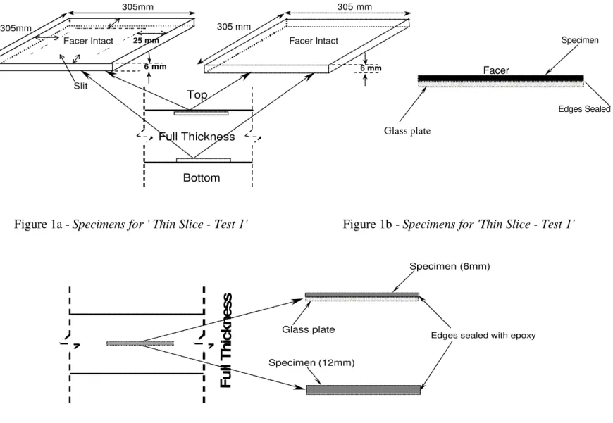
Figure 1a - Specimens for ' Thin Slice - Test 1' Figure 1b - Specimens for 'Thin Slice - Test 1'
Figure 2 - Specimens for ' Thin Slice - Test 2'
Specimen Edges Sealed Glass plate Facer side (a) (b) Slit 305mm 305mm 6 mm 25 mm Facer Intact Full Thickness Top Bottom 305 mm 305 mm 6 mm Facer Intact Full Thickness Glass plate Specimen (6mm)
Edges sealed with epoxy
Properties by Means of Heat Flow Meter Apparatus (C518). These specimens are currently exposed to a laboratory environment of 24° C (temperature) and 50% RH (relative humidity), and will be re-tested after about twelve months of exposure.
Thin-Slice Specimens - Four sets of tests are being conducted with thin-slice specimens for each of the three products. As shown in Table 2, these tests are identified as Test 1, Test 2, Test 3 and Test 4. The details of test specimens are given in Table 2 and Figures 1 and 2.
In Test 1, two 6 mm thick slices were cut from each surface (Figure 1a) (total of four) of the board and placed on an epoxy-coated glass substrate (Figure 1b). The edges of each specimen were sealed with epoxy coating to facilitate one-sided aging of the polyiso foam through the foil facer only. Two of these four specimens have the facer surface intact on the exposed side whereas the other two have a slit on the facer surface of about 25 mm from the edge (Figure 1a). The presence of the slit on the facer allows 2-D diffusion pattern, i.e., accounts also for diffusion parallel to the facer surface.
For Test 2, all the thin slices are taken from the core of the polyiso board (Figure 2a). Naturally, these core foam slices are without any facer. Two of the slices are 6 mm and the other two are 12 mm. The core slices of 6 mm thickness are subjected to one-sided aging on the glass plate and edges sealed with epoxy coating (Figure 2b). However, the 12 mm thick core slices are being tested without any kind of treatment on the two major surfaces, i.e., two-sided aging (Figure 2b).
Test 3 and Test 4 are repeat tests of Test 1 and Test 2, respectively. Preparation of
thin-slice specimens is done within around 30 days of the date of delivery of the product to the laboratory. Thin-slice specimens are exposed in the laboratory and tested for heat transmission properties at different stages of aging, using 'Heat Flow Meter Apparatus' according to ASTM C518.
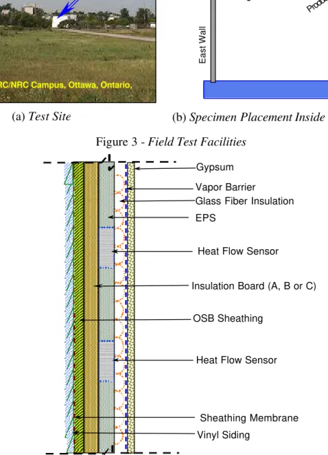
Field Test in the IRC/NRC Test Hut
Any long-term performance evaluation process is not complete without field exposure tests. In this research program, all three full-size polyiso rigid boards have been installed in a purpose-built test-hut (Figure 3a) at the IRC/NRC campus in Ottawa. The indoor environment of the test hut is controlled and exterior weather data are also available. As shown in Figure 3b, full-size boards of Product A and Product C are installed on the east wall of the test hut and Product B and Product C on the west wall. In this way, the field performance of all three polyiso products can be monitored and also the difference in performance due to wall orientation (east or west) can be identified. A typical cross-section of the wall, after installation of polyiso board in the test hut, is shown in Figure 4. The in-situ thermal properties of the polyiso foam boards are being monitored using the instrumentation set-up as described in the following paragraph.
Field Instrumentation of Specimens and Measurement - Each of the four insulation boards was instrumented with two heat flow sensors located as shown in Figures 5a and 5b. Around each heat flow sensor, seven thermocouples were installed in the locations shown in Figure 5a. The complete set-up consists of 56 type ‘T’ thermocouples and eight heat flow sensors. The data are collected by a Hewlett Packard mainframe data
acquisition system connected to a digital personal computer. Temperature and heat flow measurements are made at every three minutes.
Each of the heat flow sensors outputs an EMF voltage that is proportional to the heat flow through the sensor. Each of the sensors is calibrated separately, and the heat flow through the specimen is calculated from the output voltage of the sensor. The R-value is then calculated from the temperature distribution and the measured heat flow.
Figure 3 - Field Test Facilities
Figure 4 - Schematic Cross-section of the Test Hut Wall
Test Hut
IRC/NRC Campus, Ottawa, Ontario,
(a) Test Site (b) Specimen Placement Inside the Test Hut
East Wall West Wall
Test Hut
Product A
Product C Product B
Product C Roof
Glass Fiber Insulation Gypsum
Vapour Barrier
OSB Sheathing
Sheathing Membrane Vinyl Siding
Insulation Board (A, B or C) E P S
Heat Flow Calibrator (HFC)
Heat Flow Calibrator (HFC)Sensor
Sensor
Gypsum Vapor Barrier
Glass Fiber Insulation EPS
Heat Flow Sensor
Insulation Board (A, B or C)
OSB Sheathing
Heat Flow Sensor
Sheathing Membrane Vinyl Siding
Modeling Tool
The distributed parameter continuum or DIPAC model, developed at IRC/NRC, can be and had been used in the recent past [13] as an important tool for evaluating LTTR of foam insulation. Several publications are now available where the fundamentals of the DIPAC 1-D model have been discussed at length [9,13]. However, the DIPAC 1-D model does not have an effective provision for accommodating the lateral diffusion component of the blowing agent, i.e., the flow of gas parallel to the facer. It is envisaged that having a 2-D model of heat and gas transfer will facilitate the incorporation of the lateral diffusion component of the blowing agent into the DIPAC model.
The 2-D DIPAC model needs to include three different layers cut parallel to the facer [9,13]. The external layers represent foam with properties different from those in the central or core layer. This permits introduction of the lateral gas diffusion through the external layers. Furthermore, each external surface is provided with a contact resistance used to simulate an impermeable facer. The objective of DIPAC 2-D is to calculate the heat flux through a slab, provided with a facer on each side, as a function of aging time and boundary conditions. To achieve this, the facers and the slab are divided into a given number of layers and the aging time is counted as a number of time-steps. Some of the material characteristics used in these calculations, e.g., density, extinction coefficient for
Figure 5a - Cross-section of the Test Hut
Wall with Instrumentation
Figure 5b - Plan View (inside the test hut)
of Instrumentation 1594 mm 2324 mm 450 mm 450 mm 300 mm 300 mm 1200 mm 430 mm 1200mm 300mm 300m m 450mm 450mm 2324m m 1594m m 430m m
Heat Flow Sensor Thermocouple Siding
OSB
Insulation Samples
Heat Flow Sensor
Glass Fiber Insulation Gypsum Board
infrared radiation or effective gas diffusion coefficient, may vary across the slab. Therefore, all the material characteristics used for the input are measured at three locations: at the middle and at each surface of the slab. Using a linear interpolation one may calculate material characteristics for each layer.
Work on the development of the DIPAC 2-D model is in progress and will be used to evaluate the LTTR values when experimental results from thin-slice experiments are available.
Preliminary Test Results
Laboratory and field tests currently in progress are generating an enormous amount of useful and interesting information. However, it is beyond the scope of this paper to present all these data in an objective manner at this stage of the project. Hence, only representative and pertinent sets of test results are presented and discussed in the following sections.
Full-Thickness Specimens
The average values for the initial thermal resistivity of the three products are shown in Figure 6. The initial values appear to be very close to each other. The results obtained from six specimens for each product also show that all observations are within ±2% of the average thermal resistivity values reported in Figure 6. Hence, it confirms the fact that the results are reproducible with the Heat Flow Meter used in this study and that the variation of the material properties at different locations of the board is insignificant. The specimens are currently exposed to laboratory condition (24°C; 50%RH) and further tests on these specimens will be carried out after a period of around twelve months.
Figure 6 - Initial Thermal Resistivity of Full Thickness Impermeably Faced
Polyiso Foam Insulation Thin-Slice Specimens
As mentioned earlier, two types of thin slices are being tested in this research program. Surface slices are in Test 1 and core slices in Test 2.
0 10 20 30 40 50 60
Product A Product B Product C
Specimen ID
Thermal Resistivity
(m. K. W
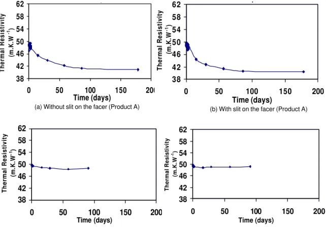
Observations from Test 1 - Typical aging (i.e., reduction in thermal resistivity with
time) curves of thin surface slice specimens, after up to six months of laboratory exposure from Test 1, with and without a slit on the facer, can be seen in Figures 7a to 7d. These results are for Product A (six months) and Product B (three months). Similar results are also available for Product C but for a much shorter time period and will be reported elsewhere in due course.
Figure 7 - Change of Thermal Properties in Thin Surface Slices (Test-1 )
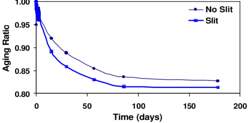
These aging curves clearly show rapid aging at the beginning of the exposure and then a reduction in the aging rate to a near stable value for Product A. In the case of Product B, however, these changes are less evident. The different aging characteristics of Products A and B imply that aging characteristics of one polyiso product can vary from another and it is necessary to investigate more that one polyiso product, as has been done in this project. There is also a clear indication that the presence of a slit on the facer in Product A results in a greater rate of aging in the initial stage but for Product B this effect is less visible at this stage. This phenomenon is more evident, for Product A, if the results are presented in terms of aging ratio (i.e., the ratio of the thermal resistivity at any specified time to the initial thermal resistivity), as shown in Figure 8. One possible explanation for the aging of the faced specimen is that in the presence of an inert cell gas the process of solubility of the blowing agent in the foam matrix will change the molar composition of the cell-gas and thereby reduce the effective thermal conductivity of the foam. Another possible explanation is the lateral diffusion of cell gases parallel to the facer. In addition, it is also possible that the facer is not effectively impermeable. The
6mm - Surface - Top - 477-20-a
38 42 46 50 54 58 62 0 50 100 150 200 Time (days) Thermal Resistivity (m.K.W -1 )
6mm - Surface - Top - Slit - 477-20-b
38 42 46 50 54 58 62 0 50 100 150 200 Time (days) Thermal Resistivity (m.K.W -1 )
(a) Without slit on the facer (Product A) (b) With slit on the facer (Product A) 6mm - Surface - Top - 477-44-a
38 42 46 50 54 58 62 0 50 100 150 200 Time (days) Thermal Resistivity (m.K.W -1)
6mm - Surface - Top - Slit - 477-44-b
38 42 46 50 54 58 62 0 50 100 150 200 Time (days) Thermal Resistivity (m.K.W -1 )
rapid aging has almost stabilized the thermal resistivity of the thin slice after 110 days when there is a slit on the facer but without it, the aging process is still continuing at 180 days. Quite naturally, further exposure of the specimens is necessary and the process is ongoing. In general, these preliminary observations of Test 1 indicate that experimentally it is possible to identify the effect of the lateral flow of the blowing agent on the aging process of impermeably faced polyiso insulation foam board. Hence, this phenomenon now can be incorporated in the DIPAC 2-D model where exterior layers would resemble the thin layers of Test 1.
Figure 8 - Aging Due to Lateral Flow of Blowing Agent Parallel to Facer (Product A)
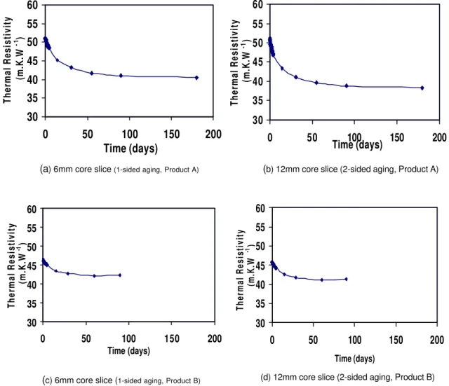
Observations from Test 2 - Figures 9a to 9d show the typical aging curves of core
slices from Test 2 for Product A and Product B. These figures indicate that, as would be expected, the initial (up to 15-20 days) aging process is rapid but thereafter it slows down significantly. However, the aging process continues beyond the test period. Figure 10 shows the plot of aging ratio vs. time for the two core slices of Product A. The two-sided aging of a 12 mm thick core slice appears to be faster than the one-sided aging of the 6 mm core slice. It should be noted that the aging ratio represents a combination of many effects. The impact on aging caused by a few hours difference in the start of the test is proportional to the second power of the thickness of each layer (here a factor of 2) and the foam itself may have a gradient of physical properties. While an analysis of these differences requires the use of a computer model, the fact that tests on core slices showed much faster aging than the surface slices in the Test 1 signifies that the impermeable facer influences the rate of aging. The aging characteristics of these core slices will help to model core elements in the DIPAC 2-D model.
Field Test Observations
After installation of the specimens in the test hut (Figure 3), the data acquisition has just started. Typical, initial recorded results for Product B on the west wall of the test hut are presented in Figure 11. The similarity between field test data and laboratory observations on the same product at around the same time clearly indicates that the entire instrumentation system used for the field observation is reliable. These tests will continue for one year. The field observation data will complement the laboratory test data and the output from the DIPAC 2-D modeling.
0.80 0.85 0.90 0.95 1.00 0 50 100 150 200 Time (days) Aging Ratio No Slit Slit
Figure 9 - Change of Thermal Properties in Thin Core Slices (Test-2) 12mm - Core - 477-21-e 30 35 40 45 50 55 60 0 50 100 150 200 Time (days) Thermal Resistivity (m.K.W -1 ) 6mm - Core - 477-21-f 30 35 40 45 50 55 60 0 50 100 150 200 Time (days) Thermal Resistivity (m.K.W -1 )
(a) 6mm core slice (1-sided aging, Product A) (b) 12mm core slice (2-sided aging, Product A)
12mm - Core - 477-45-d 30 35 40 45 50 55 60 0 50 100 150 200 Time (days) Thermal Resistivity (m.K.W -1 ) 6mm - Core - 477-45-c 30 35 40 45 50 55 60 0 50 100 150 200 Time (days) Thermal Resistivity (m.K.W -1 )
(c) 6mm core slice (1-sided aging, Product B) (d) 12mm core slice (2-sided aging, Product B)
0 10 20 30 40 50 60 11/26/01 0:00 11/28/01 0:00 11/30/01 0:00 12/2/01 0:00 12/4/01 0:00 12/6/01 0:00
Date and Time Recorded
Thermal Resistivity (m.K.W -1 ) Field Observation Product B Laboratory Observation Product B
Figure 11 - Typical Recorded Field
Test Data 0.70 0.75 0.80 0.85 0.90 0.95 1.00 0 50 100 150 200 Time (days) Aging Ratio
6mm core (1-sided aging) 12mm core(2-sided aging)
Figure 10 - Aging of Core Slices
(one-sided and two-sided aging - Product A) 6 mm core (1-sided aging)
Discussion
The work presented in the previous sections takes into account three distinct but complementary approaches, i.e., laboratory tests, field observations and numerical modeling. This comprehensive approach is designed to address the complex issue of the LTTR of impermeably faced polyiso foam insulation board.
The preliminary experimental observations show that the designed thin-slice tests can in fact identify the aging of the foam due to lateral diffusion of the blowing agent gas parallel to the facer. For appropriate quantification of this phenomenon, the ongoing series of tests need to be carefully monitored and carried to their logical end. The aging of core slices also indicate their own characteristics, which differ from those obtained from surface slices. On the other hand the preliminary results obtained from field tests show that laboratory and field observations could be correlated. However, continuous monitoring, collection of data and analysis of the data simultaneously still need to be completed in the coming days.
Summary of Observations
The following interim observations can be made at this stage from this ongoing research project.
1. A comprehensive research project to determine the long-term thermal resistance (LTTR) of polyisocyanurate (polyiso) foam insulation board with impermeable facers is currently in progress.
2. Thin-slice tests indicate that aging of polyiso foam does occur due to the lateral diffusion of the blowing agent gas parallel to the facer surface.
3. Core polyiso foam slices without any facer indicate a faster aging than surface polyiso foam slices with facer.
4. Field performance monitoring of full-size polyiso insulation board is currently in progress and preliminary test data are comparable to the laboratory observations. 5. Experimental observations from thin-slice tests show that the approach taken in the
DIPAC 2-D model to divide the polyiso foam in three different layers is both reasonable and logical.
Acknowledgement
The authors would like to acknowledge the support and comments provided by the members of Canadian Polyisocyanurate Council for the preparation of this paper. Members of the Canadian Polyisocyanurate Council are: John Letts (Firestone Building Products), Rich Roe (Atlas Roofing), Sachi Singh and Paul Coleman (Huntsman Polyurethanes), Andy Lodge (IKO Industries), Michel Drouin (Johns Manville) and John Clinton (PIMA).
References
[1] Goodacre, C., Sharples, S. and Smith, P., 'Integrating Energy Efficiency with the Social Agenda in Sustainability,' Energy and Buildings, Vol. 34, 2002, pp. 53-61.
[2] ASHRAE Handbook - Fundamentals, American Society of Heating, Refrigerating and Air-Conditioning Engineers, Inc., N.E. Atlanta, GA 30329, Chapter 22, 1997. [3] Alsoy, S., 'Modeling of Diffusion in Closed Cell Polymeric Foams,' Journal of
Cellular Plastics, Vol. 35, May 1999, pp. 247-271.
[4] Isberg, J., 'Thermal Insulation – Conditioning of Rigid Cellular Plastics Containing a Gas with Lower Thermal Conductivity than Air Prior to Determination of Thermal Resistance and Related Properties,' Chalmers University of Technology, No. 698, Goteborg, Sweden, 1988.
[5] Sherman, M., 'Aged Thermal Resistance (R-value) of Foil-Faced Polyisocyanurate Foam Thermal Insulation Board,' Proceedings of Conference on Thermal
Performance of the Exterior Envelopes of Buildings, 1979, pp. 952-964.
[6] Hagan, J. R. and Miller, R. G., 'Long-Term R-Values and Thermal Testing Requirements for Rigid Insulating Foams,' Insulation Materials, Testing, and Applications, ASTM STP 1030, D. L. McElroy and J. F. Kimpflen, Eds., ASTM, Philadelphia, 1990, pp. 205-217.
[7] Sherman, M., 'Sampling Faced Foam Insulation Board for Heat Flow Meter Thermal Performance Testing, 'Thermal Insulation Performance, ASTM STP 718, D. L. McElroy and R. P. Tye, Eds., ASTM, Philadelphia, 1980, pp. 298-306.
[8] Norton, F. J., 'Thermal Conductivity and Life of Polymer Foams,' Journal of
Cellular Plastics, Jan. 1967, pp. 23-37.
[9] Bomberg, M., 'A Model of Aging for Gas-Filled Cellular Plastics,' Journal of
Cellular Plastics, Vol. 24, July 1988, pp. 327-347.
[10] Ostrogorsky, A.G. and Glicksman L.R., 'Aging of Polyurethane Foams, the Influence of Gas Diffusion on Thermal Conductivity,' ORNL/SUB/84-9009/2,1986, pp.1-98.
[11] Schuetz, M. A. and Glicksman L.R. 'A Basic Study of Heat Transfer Through Foam Insulation,' 6th International Polyurethane Conference, San Diego, CA, 1983, pp. 341-347.
[12] Glicksman, L.R., Ostrogorsky, A.G. and Chiapetta, S., 'Effective Conductivity of Aging of Polyurethane Foam,' ORNL/SUB/84-9009/1,1986, pp.1-56.
[13] Bomberg, M. and Kumaran, M. K., 'Use of the Distributed Parameter Continuum (DIPAC) Model for Estimating the Long-Term Thermal Performance of Insulating Foams,' Thermal Performance of the Exterior Envelopes of Buildings VI, Clearwater Beach, FL,1995, pp. 15-24.
[14] Bomberg, M. and Brandreth, D.A., 'Evaluation of Long-term Thermal Resistance of Gas-filled Foams: A State of the Art,' ASTM STP 1030, American Society for Testing and Materials, Philadelphia, PA, 1990, pp. 156-173.