Publisher’s version / Version de l'éditeur:
Confronting the Barriers of Heavy Haul Rail Technology: Proceedings, 7th
International Heavy Haul Conference, 2001
READ THESE TERMS AND CONDITIONS CAREFULLY BEFORE USING THIS WEBSITE. https://nrc-publications.canada.ca/eng/copyright
Vous avez des questions? Nous pouvons vous aider. Pour communiquer directement avec un auteur, consultez la première page de la revue dans laquelle son article a été publié afin de trouver ses coordonnées. Si vous n’arrivez pas à les repérer, communiquez avec nous à [email protected].
Questions? Contact the NRC Publications Archive team at
[email protected]. If you wish to email the authors directly, please see the first page of the publication for their contact information.
NRC Publications Archive
Archives des publications du CNRC
This publication could be one of several versions: author’s original, accepted manuscript or the publisher’s version. / La version de cette publication peut être l’une des suivantes : la version prépublication de l’auteur, la version acceptée du manuscrit ou la version de l’éditeur.
Access and use of this website and the material on it are subject to the Terms and Conditions set forth at
Transitioning from corrective to preventive rail grinding on the BNSF
railroad
Stanford, John; Magel, Eric; Sroba, Peter
https://publications-cnrc.canada.ca/fra/droits
L’accès à ce site Web et l’utilisation de son contenu sont assujettis aux conditions présentées dans le site LISEZ CES CONDITIONS ATTENTIVEMENT AVANT D’UTILISER CE SITE WEB.
NRC Publications Record / Notice d'Archives des publications de CNRC:
https://nrc-publications.canada.ca/eng/view/object/?id=e615836c-246b-4db5-8c43-8ecf375457e6
https://publications-cnrc.canada.ca/fra/voir/objet/?id=e615836c-246b-4db5-8c43-8ecf375457e6
Transitioning from Corrective to Preventive Rail
Grinding on the BNSF Railroad
John Stanford – Manager Rail Maintenance, Burlington Northern Santa Fe Railroad Eric Magel - Senior Engineer, National Research Council Canada
Peter Sroba – Senior Engineer, National Research Council Canada
In 1998, BNSF started transitioning their rail from a corrective state of wear and surface fatigue back to the favored preventive state. The National Research Council of Canada developed a unique rail-grinding strategy called Preventive-Gradual to effect the transition. This strategy was shown to extend rail life through reduced wear. The rail was restored to a superior surface condition, grinder productivity increased, and cost per finished mile decreased. Techniques for managing preventive grinding programs are reviewed, and methods to optimize the preventive-gradual strategy through rail profile design, grinding pattern refinement, and determination of the optimal wear rate are presented.
Index Terms: Rail, Grinding, Preventive-Gradual
1.0 INTRODUCTION
The 54,700 km (34,000 mile) Burlington Northern Santa Fe Railroad (BNSF) was formed through a merger in 1995 of the Burlington Northern Railroad (BN) and the Santa Fe Railway (ATSF). This North American heavy haul coal, grain, intermodal and bulk commodity railroad extends from Chicago to the North American West Coast and from Canada to Mexico. Traffic density, speeds and axle loads have continuously increased over the years as BNSF improves operating efficiencies. These increases have brought about a corresponding increase in the challenge of maintaining BNSF’s infrastructure safely and efficiently, especially in the field of rail maintenance. BNSF has found rail grinding to be an essential tool in maximizing the life of its most costly asset – rail. This paper presents the techniques developed by BNSF and the National Research Council Canada (NRC) to maximize BNSF’s return on investment in its rail grinding program.
1.1 BNSF Rail Grinding History
Rail grinding has been an important component of the BNSF rail maintenance program for the last 40 years [1]. The BN began grinding in the 1960’s to remove corrugation and head flow. By 1987 BN’s grinding program had evolved to a corrective profile grinding strategy on curves at 31.5 million gross tonnes (mgt) (35 million gross tons) (MGT) intervals, grinding to a strong 2 point contact between the wheel and the rail. The rail surface was in good condition, however rail-wear rates were excessive because of the contact profile.
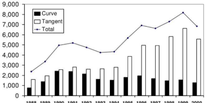
BN modified its grinding policy in 1988 to introduce a conformal one-point wheel/rail contact condition in order to reduce rail-wear rates. Grinding intervals were lengthened to as much as 81 mgt (90 MGT) and grinding speed increased by 40%. The increased grinding speed, longer grinding intervals and reduced grinding of the gage-corner led to increased fatigue damage on curves, and detail fracture rates increased dramatically (figure 1).
In 1991 the BN changed its grinding approach again, instituting a mild 2 point contact profile utilizing the NRC-Loram BAR gage templates designed by the National Research Council Canada (NRC), and curve grinding intervals of 16 to 36 mgt (18 to 40 MGT) were implemented. By 1995 the BN had fully established a preventive grinding program. The rail surface was again in good condition and curve detail fracture rates had declined.
0 1,000 2,000 3,000 4,000 5,000 6,000 7,000 8,000 9,000 1988 1989 1990 1991 1992 1993 1994 1995 1996 1997 1998 1999 2000 Curve Tangent Total
The merger of the BN and the ATSF in 1995 to form the BNSF brought traffic, tonnage and territory increases, however without a proportional increase in grinding resources. Track time available for grinding steadily decreased, resulting in additional lost productivity. By the end of 1997 BNSF had slipped back to a corrective grinding strategy as grinding intervals fell to 54 to 181 mgt (60 to 200 MGT). Rail condition deteriorated rapidly, and detail fracture rates on tangent rail had increased by 76% over 1994 levels (figure 1).
1.2 The Cost of Corrective Grinding
BNSF and many other railroads have demonstrated that preventive grinding is the most effective rail maintenance practice [1, 2]. Preventive grinding is characterized by frequent, high speed grinding in a predominantly single pass operation. Even in the best premium rail, micro-cracks develop at the most stressed portion of the rail surface within 4.5 to 7 mgt (5 to 8 MGT). These cracks grow very slowly in their early stages, however their growth rate accelerates with time. The preventive grinding strategy addresses the damaged surface of the rail before the cracks enter their stage of rapid growth. The rail surface is maintained to control contact stress and promote wheelset steering, while retaining its work hardened layer to resist crack initiation and growth.
Corrective grinding in contrast utilizes infrequent, low speed, multiple pass grinding to address visible and often severe rolling contact fatigue damage. Rail profile on sharp curves deteriorates within 18 mgt (20 MGT), thus subjecting the rail to higher contact stresses for longer intervals and resulting in very deep cracks. Rail profiles with additional relief on the gage-corner must be utilized to prevent excessive gage-corner contact as the profile deteriorates, resulting in accelerated wear rates. The heavy metal removal required in corrective grinding removes the work hardened layer of the rail, further accelerating wear and profile deterioration.
Tests conducted on BN and BNSF demonstrate wear rates (combined grinding and wear) on sharp curves up to 45% higher under corrective grinding than with preventive grinding. Annual grinding passes required to maintain curves are up to 35% higher with corrective grinding [1, 3]. Corrective grinding also results in reduced efficiency in the utilization of the grinding equipment. Track occupancy time for performance of maintenance tasks is at a premium on heavy haul railroads. Maximum track window length on BNSF is often 2 hours or less on heavy traffic single track lines. Because of the multiple corrective passes required in corrective grinding, track segments often cannot be completed in one track window - resulting in significant travel time to clear for traffic. On BNSF, grinding equipment in work mode must travel at a speed able to stop within half the range of vision short of obstructions. On
heavily curved territory maximum safe travel speeds are often 16 kph (10 mph) or lower.
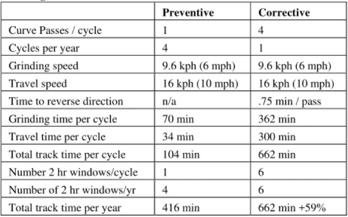
Table 1 examines grinding equipment utilization on a heavily curved single track segment on BNSF under preventive and corrective strategies. This segment is 17.7 km (11 miles) long with 27 sharp curves totaling 11.3 km (7.0 miles). Locations to clear equipment for traffic are available at each end of the segment. Table 1 shows that in this example corrective grinding requires 59% more time than preventive grinding to grind the curves in the segment. In practice the preventive grinding efficiency is even greater, as fewer passes per year would be required than for corrective, and higher grinding speeds could be utilized.
Table 1: Track Time Comparison of Preventive and Corrective Grinding
Preventive Corrective
Curve Passes / cycle 1 4 Cycles per year 4 1
Grinding speed 9.6 kph (6 mph) 9.6 kph (6 mph) Travel speed 16 kph (10 mph) 16 kph (10 mph) Time to reverse direction n/a .75 min / pass Grinding time per cycle 70 min 362 min Travel time per cycle 34 min 300 min Total track time per cycle 104 min 662 min Number 2 hr windows/cycle 1 6 Number of 2 hr windows/yr 4 6
Total track time per year 416 min 662 min +59%
2.0 TRANSITIONING FROM CORRECTIVE TO PREVENTIVE GRINDING
In 1997 BNSF recognized the need to re-establish a preventive grinding program. Traditional methods of implementing preventive grinding programs required significant short-term increases in grinding resources to first restore all of the rail to a good profile and clean surface condition before preventive cycles could be implemented. This was not a practical alternative for BNSF however as no additional funds were available to support the initial increase in grinding required.
BNSF contacted the National Research Council Canada for assistance in developing a preventive grinding program. The NRC was tasked to formulate a strategy for transitioning an entire territory from a corrective to a preventive mode. BNSF specified that any strategy developed must prove its economic benefits over current practices, produce rapid results, and be accomplished without any increase in the annual grinding budget. In response to these requirements NRC developed a new grinding strategy termed “preventive-gradual” [3].
2.1 The Preventive-Gradual Grinding Strategy
The preventive-gradual grinding strategy involves embarking straight onto preventive grinding intervals from
the current corrective scheme without first undertaking the expensive task of “cleaning” all the rail. The rail is transitioned to the desired profile and crack-free state on a gradual basis. This strategy starts with frequent one-pass grinding as with traditional preventive grinding, but with additional metal removal each pass – a method that only becomes feasible with today’s modern high-performance grinding equipment. The objective is to immediately gain the benefits of an optimized preventive grinding strategy while gradually catching up to the profile and surface cracks.
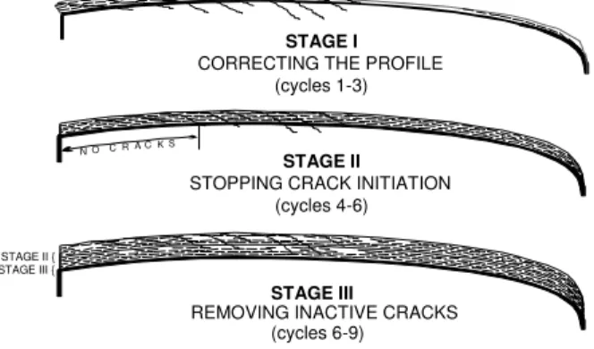
Figure 2 shows the staged profiling and crack removal process. The desired NRC rail profile is achieved in Stage 1 of the strategy with one to three passes. Stage 2 includes the next one to three cycles, which gradually stop the initiation of new cracks. The final stage consists of a further one to three cycles to remove the remaining inactive cracks to produce a clean rail surface. The entire process typically takes three passes on tangent and shallow curves, and up to nine passes on sharp curve low-rails.
Two essential components of the preventive-gradual strategy are effective lubrication and proper track gage. Lubrication significantly reduces lateral forces in a curve, essential to keeping contact stresses on the rail at manageable levels [4]. Wide gage in curves causes the false flange on hollow wheels to come in contact with the running area of the low rail, resulting in very high contact stresses and poor wheelset steering.
2.2 The Pacific Northwest Grinding Initiative
BNSF implemented the preventive-gradual strategy on its Pacific Northwest (PNW) corridor in February 1998 [2]. This territory consists of 8,300 track-km (5160 track miles) with annual tonnage over the core routes of 27 mgt (30 MGT) to 81 mgt (90 MGT). A significant proportion of the track consists of sharp curves on concrete ties with heavy mountain grades. Rail in sharp curves is predominantly 136RE deep head-hardened premium rail. One 88 stone rail grinder maintains this corridor. The PNW was selected because it was determined to be the most demanding of BNSF’s four grinding territories, and most likely to rapidly
demonstrate the success or failure of the preventive-gradual strategy.
At the onset of the program BNSF and NRC formed a project management team consisting of representatives from BNSF engineering and field departments, NRC and the grinding contractor to bi-weekly monitor and direct the program’s progress. Training sessions were held with BNSF field maintenance personnel to explain the project goals and requirements. Monitor and test sites were established to track performance of the program. NRC examined these sites before and after each grind cycle to track performance and collect wear and grinding data for comparison to other grinding strategies.
Grinding cycle intervals were established of 13.5 mgt (15 MGT) on sharp curves 3.5 degrees or greater, 26 mgt (30 MGT) on mild curves and 41 mgt (45 MGT) on tangent track.
The preventive-gradual grinding strategy had begun demonstrating significant benefits by the end of the first year. Visible rail surface defects had decreased, 98% of the rail was at the desired profile, and test site measurements verified that rail wear and grinding costs were reduced compared to other grinding strategies [3].
3.0 INTERMEDIATE TRANSITION TO MAINTENANCE GRINDING
While the preventive-gradual strategy was being tested on the PNW, the BNSF was still faced with the question of how to address the remainder of its railroad. As grinding intervals grew longer in 1996 and 1997 the grinding program became almost exclusively out-of-face - all tangent and curves ground each cycle. The complete tangent grind each cycle further lengthened the time required for each cycle, causing grinding intervals to fall further and further.
Improvement of rail surface condition on curves was identified as the highest initial priority. BNSF decided to decrease the interval between curve cycles by increasing the tangent cycle interval. A minimum cycle interval of 72 mgt (80 MGT) was established for tangent, with tangent cycles on each segment alternating with curve only cycles. With 75% of BNSF’s track miles being tangent, this reduced the time required to complete each grinding cycle by 20%. Grinder productivity improved through more efficient utilization of track time on the curve-only cycles, and passes per curve decreased as the cycle interval grew shorter. Total track time availability also increased through the ability to utilize shorter track windows. At the end of 1999 on BNSF’s non-preventive grinding territories average cycle interval had been reduced by 30% from 56 mgt (62 MGT) to 38 mgt (42 MGT), passes per curve per cycle had declined from 3.9 to 2.2, and curve rail surface condition had improved.
N O C R A C K S
STAGE I
CORRECTING THE PROFILE (cycles 1-3)
STAGE II
STOPPING CRACK INITIATION (cycles 4-6)
STAGE III
REMOVING INACTIVE CRACKS (cycles 6-9)
STAGE II { STAGE III {
Figure 2: Staged Crack Removal with the Preventive-Gradual Strategy
Based upon the initial success of the PNW preventive-gradual strategy in its first year, BNSF began expanding other grinder territories to the preventive-gradual strategy. In May 1999 BNSF implemented a second preventive-gradual program on its 6760 track-km (4200 track-mile) Coal Loop corridor, serving the Powder River Basin coal fields in Wyoming and Montana. Annual tonnages on this corridor range from 54 to 300 mgt (60 to 330 MGT) on predominantly concrete tie track. A third 7240 track-km (4500 track-mile) program was instituted in August 2000 on BNSF’s transcontinental main line between Los Angeles and Chicago. Since then, preventive-gradual programs on additional lines with heavy curvature have been added to BNSF’s other grinder territories.
The intermediate maintenance grinding transition helped accelerate the ‘gradual’ phase when the preventive-gradual strategies were adopted, though this was not as cost effective as direct adoption of preventive-gradual would have been.
4.0 MANAGING THE PREVENTIVE-GRADUAL GRINDING PROGRAM
The benefits of preventive-gradual grinding demonstrated in the first year of the PNW initiative would not have been possible without vigilant management of the grinding program. Cycle intervals, grinding pattern selection, and rail condition were closely monitored throughout the program and adjusted to meet changing conditions.
4.1 Grinder Scheduling
Maintaining the appropriate cycle interval on each line ground is the most critical factor in the success of any preventive grinding program, and even more so for preventive-gradual. It can also prove to be most daunting. Arrangement of the grinding territory in a loop, with the annual tonnage on individual lines even multiples of a base tonnage, is the best configuration to minimize equipment travel and variance from the desired interval. Unfortunately most railroad’s physical characteristics seldom match this ideal. In the case of the PNW the core loop had a relatively constant tonnage level throughout, however some segments of the loop had a very low percentage of sharp curves and several segments radiated outward from the loop like spikes, both resulting in increased equipment travel times. It was found that for some locations it was more economical to continue grinding sharp curves correctively. The increased passes and rail wear were offset by savings in travel time. Because BNSF operating rules dictate slower travel speeds for equipment in work mode than when deadheading from terminal to terminal, it was even economical in some cases to travel over sharp curves without grinding. A simple economic model was developed to aid in determining if a sharp curve cycle should be used. On lines which must be traversed
regardless of the grinding plan, selecting the minimum of equations (1) and (2) yields the lowest cost:
Cprev = Cday Vwork D +Lsharp Cprevgrind (1)
Ccorr = Cday Vtvl D +3 Lsharp Cgrindcorr + k Crail Lsharp (2)
Where Cprev = Cost to grind sharp curves preventive
Ccorr = Cost to grind sharp curves corrective
Cday = Equipment operation cost per day
Cgrindprev = Grinding cost per distance ground
Cgrindcorr = Grinding cost per distance ground
Crail = Rail relay cost per length
D = Distance to travel
Lsharp = Length of all sharp curves
Vwork = Travel speed in work mode (dist/day)
Vtvl = Travel speed in travel mode (dist/day)
k = Parameter for increased rail wear per
corrective cycle (0.01 on BNSF)
On lines which would be traveled only if the sharp curve cycle is ground, the minimum of equations (3) and (4) would apply:
Cprev = 2 Cday Vwork D +Lsharp Cprevgrind (3)
Ccorr = 3 Lsharp Cgrindcorr + k Crail Lsharp (4)
BNSF also developed a software scheduling model to aid in tracking and managing cycle intervals. The model projected the number of days required to grind each subdivision based upon curve characteristics of the line, the type of grinding being done, and historical track time availability and equipment utilization. The accumulated tonnage between grinding intervals was then projected over a two year schedule time span to identify areas and times where a cycle failure might occur. This model proved essential to projecting the long term ramifications of any deviation or change to the schedule, allowing decisions to be made accordingly.
Even with the best planning however, events can occur which cause a grinding cycle to be skipped on a track segment. In its three years of experience with preventive-gradual BNSF has had to contend with track maintenance blitzes, derailments, rockslides, and National Forrest closures due to extreme fire danger. In these situations the important factor is to maintain the cycle intervals on the remainder of the program. BNSF’s experience is that if the segment skipped is less than 5% of the total program length then it can be addressed with additional work on the next cycle without affecting the program as a whole. 4.2 Cycle Intervals
The preventive-gradual cycle intervals were initially selected based upon past preventive intervals [2], the improved metal removal capabilities of today’s grinding equipment, and on recent studies by the Association of American Railroads [5]. These studies suggested that
newer premium steels could survive longer in track without developing surface fatigue and plastic flow due to improved hardness and cleanliness.
4.2.1 Sharp Curves
Curve inspections prior to each grinding cycle revealed that visible fatigue damage on premium rail in sharp curves began increasing rapidly at between 12.6 to 14.5 mgt (14 to 16 MGT) of traffic, especially on low rails. This indicated that 13.5 mgt (15 MGT) was a good target interval. It was found that at intervals up to approximately 15.5 mgt (17 MGT) this damage could be controlled by reducing grinding speed, however at longer intervals the damage could not be reliably corrected with one grinding pass. Rail corrugation was the one surface condition that could not be addressed with the single-pass preventive-gradual approach. Multiple grinding passes had to be made when the corrugation depth was greater than the grinder was able to remove in one pass, or the corrugation would grow at a faster rate than the grinder could remove each cycle. Once corrugation conditions were corrected they did not re-develop in over 99% of the curves.
Maintaining proper track gage was identified at the start of the program as being critical to support 13.5 mgt (15 MGT) intervals. Experience in the PNW on sharp curves with between 12.7 mm (.5 in) and 19 mm (.75in) wide gage showed that although 13.5 mgt (15 MGT) intervals were able to maintain the existing rail condition, heavy damage on low rails from the false flange of hollow-worn wheels prevented the rail condition from improving. On curves with more than 19 mm (.75 in) wide gage, single grinding passes were not able to maintain a steady-state and rail condition declined. It was found necessary to apply a second grinding pass to the low rails on 10% of the sharp curves each cycle because of wide track gage.
Application of the preventive-gradual strategy to light tonnage lines with older non-premium rail on sharp curves showed that standard rail could not withstand the fatigue damage and plastic flow which occurred with 13.5 mgt (15 MGT) intervals. Much shorter grinding intervals would be necessary for preventive-gradual to succeed under these conditions. BNSF continues to correctively grind sharp curves on these lines.
4.2.2 Mild Curves
Mild curves at 27 mgt (30 MGT) grinding intervals yielded similar results to the sharp curves, however track gage played a lesser effect on damage to the low rail due to less steering and lower shear forces. After the third grinding cycle however, it was observed that the profile and surface condition on mild curves between 2.5 degrees and 3.5 degrees was not improving, especially for those on concrete ties. The sharp curve curvature criteria was lowered to 2.5 degrees during the ‘gradual’ phase of the program to
include these curves. Once they were restored to proper profile and clean surface condition, the mild curve cycle intervals were successfully re-adopted.
4.2.3 Tangent
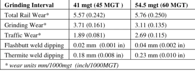
The NRC established and monitored a test site to evaluate the relative merits of 41 mgt (45 MGT) and 54.5 mgt (60 MGT) grinding intervals on tangent. The test results (Table 2) showed no presence of rolling contact fatigue after grinding in either site, and that total rail wear was the same with both grinding intervals. The site specific dipping of thermite welds was determined to be the governing factor dictating required metal removal rates.
Table 2: Comparison of Tangent Wear and Weld Dipping
Grinding Interval 41 mgt (45 MGT ) 54.5 mgt (60 MGT)
Total Rail Wear* 5.57 (0.242) 5.76 (0.250) Grinding Wear* 3.71 (0.161) 3.11 (0.135) Traffic Wear* 1.89 (0.081) 2.69 (0.115) Flashbutt weld dipping 0.02 mm (0.001 in) 0.04 mm (0.002 in) Thermite weld dipping 0.18 mm (0.008 in) 0.23 mm (0.010 in)
* wear units mm/1000mgt (inch/1000MGT)
Selection of the appropriate tangent interval is thus a function of the grinding cost per passmile vs. speed, which necessarily differs with each grinding contract. For BNSF tangent intervals of 54.5 mgt (60 MGT) were found to be most economical.
4.3 Pattern Selection
Selecting the best grinding pattern and equipment speed for each curve is especially important with preventive-gradual grinding because the single-pass operation does not provide a second opportunity until the next cycle. Patterns must be selected based upon their ability to restore profile as well as remove any surface damage present in the rail.
BNSF has two Grinding Supervisors assigned to each rail grinder. These supervisors monitor the rail condition through visual and electronic inspection to select the appropriate pattern and speed for each curve, in addition to ensuring the safe and efficient operation of the grinding equipment. These individuals are also essential in monitoring the progress of the program through pre-grind and post-grind inspection of the rail condition.
5.0 OPTIMIZING THE RAIL GRINDING PROCESS BNSF had achieved significant improvements in rail wear, rail surface defects and grinder productivity by the middle of 1999. Tangent detail fracture rates had continued escalating however (figure 1), even in the PNW territory where 41 mgt (45 MGT) grinding intervals had been employed. Although curve detail fracture rates across the system had declined slightly, they had actually increased by over 50% in the PNW territory since the preventive-gradual program had begun. It was obvious that preventive
grinding intervals and improved rail surface condition alone were not sufficient to control detail fracture rates. BNSF enlisted the aid of its grinding contractor, Loram Maintenance of Way Inc., and the NRC to devise a strategy to reduce detail fracture rates while also improving the efficiency of the preventive-gradual process. This effort was directed towards three primary areas: developing rail profiles to optimize wheel/rail interaction, determining the optimal grinding metal removal rate for preventive-gradual cycle intervals, and refinement of the rail grinding patterns. 5.1 Optimizing Rail Profiles
An optimized grinding practice includes target rail-grinding profiles that promote a healthy wheel/rail interaction and reduce the rate of profile deterioration between grinding cycles. The NRC has developed a proprietary pummeling model [6] that applies measured worn wheel profiles to candidate rail profiles and derives distributions of contact stress, fatigue damage, stability and curving performance. Through an iterative process, the pummeling model is used to engineer rail profiles that optimize the wheel/rail interaction in tangent and curved track.
5.1.1 Rail Template Designs for BNSF
For the PNW region, 800 wheels were profiled and an “average worn wheel profile” was generated. This average wheel was subsequently superimposed onto the existing NRC-LORAM Bar Gage profiles under a variety of measured track gage values and assumed values of rail rotation. The application criteria for the NRC templates were revised to specifically suit the PNW operation (Table 3). Analysis showed that the revised templates not only improve the wheel/rail interaction but also significantly reduce the amount of metal removal required for profiling [3].
In the Coal Loop, 1500 wheel profiles were measured from coal, intermodal and mixed freight trains. Dynamic rail rotation was measured in curves and tangent track on concrete ties. Rail profiles were measured in specific categories of curves and tangent track. Wheelset angle of attack was measured using a laser based system mounted on tangent track in between two mild curves. This information was applied in the new NRC pummeling model and it was
shown that NRC-LORAM Bar Gage profiles were not optimal for the Coal Loop. A family of five different custom rail profiles were designed for the Coal Loop and are shown below in Table 3.
5.1.2 Coal Loop Tangent Rail Profiles
The BNSF Coal Loop consists of 76% percent tangent track, with only 3% sharp curves (>2.5º). An analysis of the measured wheel profiles showed a considerable number of hollow wheels, especially on intermodal vehicles [7]. Hollow wheels are responsible for significant damage to the low rail of sharp curves, especially if there is wide gage greater than 12.7 mm (0.5 in). Hollow wheels are also responsible for high lateral track forces (and low rail roll-over derailments) and hunting in tangent track. Not only do they impact on track damage, hollow wheels cause rapid truck deterioration and increased fuel consumption by locomotives [8].
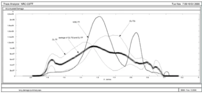
The Coal Loop track has good gage on tangent track (±3 mm of nominal) and a central 200 mm (8 in) radius running band. Continuous running at the same contact band promotes hollowing at that position. The NRC developed new templates that provide two distinct running bands, separated by about 12 mm (0.5 in) – one biased towards the gage TG) and the other biased towards the field (CL-TF). Both profiles were designed to avoid excessive reshaping of the rail by grinding, minimize contact stress, minimize surface damage, improve curving and minimize the potential for hunting. Figure 3 illustrates the impact of
the new profiles on the distribution of contact – together the profiles broaden the pattern of wear on the wheel tread, reducing both the number of hollow wheels that develop
Figure 3: Contact distribution using the two CL templates when compared with the existing NRC-TT.
Location Old PNW CL Curvature Gage Old PNW CL
Sharp Corrective H4 H3 HS > 3.5o > 2.4 mm (1 in) L2 L3 L10
Preventive > 7o H4 H2 HS > 3.5o > 12.7 mm (1/2 in) L2 L2 L10
Preventive 3.5o to < 7o H4 H2 HS > 3.5o < 12.7 mm (1/2 in) L2 L1 L10
Preventive 1.5o to < 3.5o H3 H1 HM < 3.5o < 12.7 mm (1/2 in) L2 TT L10
Preventive < 1.5o H2 TT TG/TF < 1.5o All L1 TT TG/TF
Tangent TT TT TG/TF
High rail Low rail Template
Table 3: Comparison of revised NRC grinding templates on BNSF (“old” 1997, Pacific NorthWest “PNW” since 1998, Coal Loop “CL” starting 2001).
and reducing the rate at which they hollow. The benefits of this profile strategy will be increased rail life in both curves and tangent track, reduced grinding effort, lower lateral track forces (through better steering overall), increased wheel life and reduced fuel consumption.
5.1.3 Coal Loop High Rail Profiles
Optimal high rail profiles must avoid concentrations of stress and fatigue and maximize the vehicle curving performance. Pummeling analysis showed that the NRC high rail templates exhibit excessive contact-stress and poor curving when mated with the Coal Loop worn wheels. Much improved profiles were developed for the high rail of mild (CL-HM) and sharp curves (CL-HS). Figure 4 illustrates the substantial improvement in fatigue damage distribution for the new profiles compared with the current NRC templates. The amount of metal that must be removed to re-profile the rail is reduced by 0.38 mm (0.015 in) and 0.63 mm (0.025 in) for mild and sharp curves respectively. As well, the steering performance of vehicles is substantially improved.
5.1.4 Coal Loop Low Rail Profiles
The presence of hollow wheels on heavy haul railroads has dictated heavy field side grinding in the past. The BNSF required even more field-side relief of the low rail than most, due to wide gage problems in curves. Under preventive grinding and with modern steels, less metal needs to be removed. A pummeling analysis was carried out on the three NRC low rail templates, and an improved design, called the CL-L10, was eventually developed. As it was impossible to avoid low-rail/false-flange contact without removing a prohibitive amount of metal, NRC chose instead to reduce the contact stress associated with each contact by using a 250mm (10 in) head-radius instead of the existing 200mm (8 in). The final design reduced the surface damage index by 30% for mild curves and 23% for sharp curves. The steering moment was little affected by the low rail design. The CL-L10 reduces metal removal by 75% compared to the NRC-L2 (figure 5), which translates into improved rail grinding production and increased rail
life. The CL-L10 will be applied to all low rails of mild and sharp curves, rather than the three profiles currently used.
5.2 The Optimal Metal Removal Rate
The optimal wear rate is the rate of wear required to just control rail surface fatigue. Insufficient wear results in rail fatigue, while excessive wear reduces rail life. The optimal wear rate will vary across a property and depend on differences in tonnage and axle load, type of traffic, rail metallurgy, track curvature, environment / season, track gage, lubrication standards, etc. Under preventive (gradual) grinding, the grinder should remove only a thin skin of fatigued and micro-cracked metal from the rail surface, artificially controlling the wear rate but leaving behind a healthy work-hardened layer.
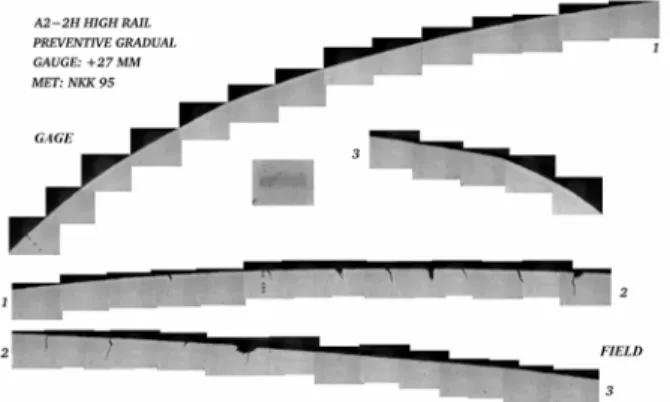
The NRC determined the optimal wear rate by first analyzing service worn premium rail samples from the PNW to determine the fatigue crack growth rates and direction of propagation. As shown in the micrograph of Figure 6, the sharp curvature (6º), high-rail gage corner of was free of fatigue while only short, approx. 0.35mm (0.014 in), perpendicular cracks were found on the ball of the rail. This demonstrated that the current grinding interval and metal removal rate on sharp curves was adequate to control fatigue. The same study found that a 27 mgt (30 MGT), one-pass grinding program, was unable to control surface fatigue - much deeper, 1 mm (0.040 in) oblique cracks populated the rail [9].
The NRC next examined metal removal plots generated from before and after grind profile measurements at the test
A) B)
Figure 4: Plot of A) surface fatigue distribution for the NRC-H1 and CL-HM in mild curves and B) the distribution of expected internal fatigue damage for NRC-H2 and CL-HS profiles in sharp curves.
Figure 6: Distribution of surface cracks in a sharp-curve high-rail under preventive grinding.
Figure 5: A comparison of the new CL-L10 and previous NRC-L2 rail templates.
curve sites. These were compared to dye penetrant photographs showing the state of cracks on the rail surface to determine if the metal removal at various locations on the rail was sufficient. These were examined over several grinding cycles on each curve to determine the minimum metal removal required to control crack formation and growth.
The optimal metal removal rate for sharp curve high rails at 13.5 mgt (15 MGT) grinding intervals was found to be 0.1 mm (0.004 in) on the center ball area and 0.25 mm (0.010 in) on the gage corner. These figures also correlated with NRC’s findings in studying metal removal and cracks at 41 mgt (45 MGT) tonnage intervals (§ 4.2.3). These metal removal depths were adopted as minimum metal removal targets for all curves on preventive cycles. BNSF elected to increase the minimum metal removal rate for tangent at 54.5 mgt (60 MGT) intervals to 0.15 mm (0.006 in) ball and 0.30 mm (0.012 in) gage to account for the longer interval and to control weld dipping.
The final step of implementing the optimal metal removal rate required determining the metal removal for each of BNSF’s grinding patterns at various grinding speeds. Loram collected over 500 metal removals at speeds ranging from 9.6 to 19.2 kph (6 to 12 mph) behind its grinding machine working on the PNW [10]. Loram analyzed the collected data and developed tables for each pattern giving the maximum grinding speed to ensure the optimal metal removal rate at a 90% confidence interval. These maximum grinding speeds were instituted on all grinding territories.
Comparison of the grinding speeds recommended by the optimal metal removal rate to typical speeds actually used on curves revealed that most grinding was done at speeds below the maximum speed – indicating an opportunity to improve grinding and rail wear performance by increasing speed. On tangent however, grinding speeds up to 50% higher than the maximum recommended were in use. Although the metal removal at the higher speeds was sufficient to maintain the desired rail profile, close examination of the rail surface showed that older pre-existing fatigue cracks were not being addressed.
5.3 Grinding Pattern Refinement
BNSF has used generally the same grinding patterns since 1993. These patterns were fine-tuned when created to match the existing rail condition to the NRC-Loram BAR Gage profiles. As grinding machine configurations changed over the years the patterns were automatically mapped to the new equipment configurations, introducing minor variations from the original pattern at each iteration. The typical rail shape also changed over time due to changing traffic, loads and wheel profiles. The two factors combined to result in patterns which often exhibited ridges at various locations on the rail surface, and were not well suited to meeting the rail profiles desired.
A redesign of the grinding patterns was necessary to improve the efficiency of the preventive-gradual strategy. Rail and profile specific patterns concentrate the metal removal where it is needed most to address profile and rail surface conditions without wasted metal removal on areas of the rail which don’t need it. Improved patterns also reduce crack growth rates through closer conformance to the desired profile and better geometric smoothness. BNSF developed a proprietary software model based upon the principles of Malkin [11] and Kalousek et al [2] to model grinding pattern metal removal on an individual grinding wheel basis. This technique allowed the examination of the effects initial rail shape and prior grinding facets have on the metal removal distribution. Rail profiles prior to grinding were collected and superimposed against the desired rail templates to generate the metal removals required. New patterns were then designed to duplicate those proportions across the rail surface.
Examination of the existing patterns with the model revealed areas on the rail with very wide facets and sharp delta angles between them. These geometric deviations result in higher contact stresses on the rail. Under elastic theory the wheel and rail surfaces first come into contact at one point. Under full loading the two bodies approach each other by 0.1 mm (0.004 in), which is called the Hertzian spring [6]. The contact stress between these two bodies will be greatest at the points which came into early contact and least at points which came into contact last. The model was used to redesign the patterns to reduce the facet widths and improve the geometric smoothness of the surface. At the beginning of the PNW initiative the grinding machine on that territory was reconfigured from an “X” pattern design, a symmetrical configuration with grinding angles working from the gage and field towards the ball then back down to the gage and field, to a “V” pattern design, where the grinding angles progressed from the gage and field at the front of the machine to the ball at the rear of the machine. The “V” configuration was believed to offer a more efficient metal removal distribution for the preventive-gradual strategy. BNSF’s model showed that the “V” was more efficient, however with one potentially significant side effect. On most patterns the first two or three gage corner facets ground were completely covered by facets of the following grinding wheels. Although the first wheel was grinding at 45 degrees to gage, the angle of the first facet left on the rail surface was between 30 and 38 degrees. 45 degree gage facets are believed to be important to preventing shell development [12], and in reducing contact stress at the lower gage corner. This potential problem was resolved by inverting the order of the first three grinding wheels, thus ensuring that a 45 degree facet is left.
6.0 RESULTS
Through adoption of the preventive-gradual grinding strategy BNSF has achieved significant productivity gains in its rail grinding program. Comparing 2000 performance to 1997, grinder utilization improved by 31%, grinding passes per curve per year decreased from 3.9 to 2.4, and the mean cycle interval declined from 56.2 to 24.5 mgt (62 to 27 MGT). These gains directly translated into the ability to cover more territory with the same amount of grinding resources, at a lower cost.
6.1 Rail Wear
A 8 km (5 mile) long test area was established on the PNW corridor to measure the effects of different grinding strategies on rail wear. The test site consisted of 10 curves between 5°51’ and 6°31’ curvature, and two mild curves. Train speeds averaged 48 kph (30 mph) at under balanced speed, on concrete tie track. Annual tonnage during the test varied between 55.3 and 60.7 mgt (61 and 67 MGT). The following grinding strategies were applied to specific curves in the test site to determine the relative merits of each approach:
• No Grind – Correctively ground prior to the beginning of the test to remove all visible surface defects, then left unground for the duration of the test.
• Maintenance – Correctively ground at 27 mgt (30 MGT) intervals
• Corrective – Correctively ground at 54.5 mgt (60 MGT) intervals
• Preventive-Gradual – 1 pass preventive-gradual intervals of 13.5 mgt (15 MGT)
• Preventive-Immediate – Correctively ground at the start of the test, then 1 pass preventive grind at intervals of 13.5 mgt (15 MGT)
Rail surface conditions were extremely poor at the beginning of the test. All curves except the preventive-gradual received 3-5 passes on the high-rails and 5-9 passes on the low rails to remove all visible surface defects and cracks.
Rail wear test results after the first year of the PNW preventive-gradual initiative were presented in [3]. The test sites continued to be monitored over the second year of the program until 113 mgt (125 MGT) of traffic and 8 grinding cycles of 13.5 mgt (15 MGT) intervals had been completed. The second year rail wear data is shown in figure 7. Although the no-grind scenario exhibited low wear, the development of severe spalling and corrugation on the low rail, and heavy checking and shell development on the high rail precluded this approach as a viable option.
Two fixed wayside rail lubricators were installed in the test site at the end of the first year. Gage face rail lubrication
improved significantly in the second year, as evidenced by the lower gage face wear for all strategies except no-grind.
The effects of wide gage on low rail wear can been seen in the second year preventive immediate results. False flange contact on the center of the low rail caused rapid flattening, fatigue crack formation and accelerated rail wear.
The test results show that the preventive-gradual method is the most effective strategy for minimizing total rail wear. As a result of the preventive-gradual strategy and improved rail lubrication practices, BNSF’s 2000 curve rail relay program was 44% lower than 1997 levels.
6.2 Rail Surface Condition
In the test site the gradual and preventive-immediate curves demonstrated the best and most consistent rail surface condition, while corrective and no-grind yielded the worst, with significant checking, shells, spalls and corrugation.
Rail surface condition on BNSF has improved dramatically on its preventive-gradual territories. Premature rail relay because of rail surface condition in 2000 was 53% lower. Additionally main track rail detection exceptions, where poor rail surface condition prevents ultrasonic rail flaw inspection, have decreased from 238 locations in 1998 to 5 in 2000.
6.3 Detail Fracture Rates
Tangent detail fractures in 2000 declined 16% from 1999 levels, the first significant reduction in 8 years. Detail fractures on curves were at a 10 year low. BNSF believes these reductions are a direct result of the grinding optimization methods instituted at the end of 1999 (§ 5). 7.0 CONCLUSIONS
The preventive-gradual grinding strategy has been shown to be the most effective approach for transitioning a rail maintenance program to preventive grinding. The strategy allows preventive grinding intervals to be adopted immediately, without the initial cost of restoring the rail to a good surface condition, and with no increase in grinding
Figure 7: Grinding strategies in the test site, showing total wear from grinding and traffic after 125 MGT (bottom segment of each bar shows results at end of first year).
0 1 2 3 4 5 6 7 8 9 10 Preventive Gradual 11.9 (0.47) 6 30' 13.5 (15) Corrective 9.9 (0.39) 6 06' 54.5 (60) Prev. Immediate 22.9 (0.9) 6 06' 13.5 (15) Maintenance 21.1 (0.83) 5 51' 27 (30) No Grind 7.9 (0.31) 6 31' 0 mm 0 0.05 0.1 0.15 0.2 0.25 0.3 0.35 inches
High Gage Wear High Vertical Wear Low Vertical Wear dummy
Strategy Wide Gage mm (in) Curvature Cycle mgt (MGT)
cost. Preventive-gradual is a significant improvement over corrective grinding strategies, benefits of lower rail wear, improved surface condition and lower grinding cost. Like any preventive grinding approach, a preventive-gradual program must be carefully managed to achieve the maximum benefit. Cycle intervals must be closely adhered to and rail condition monitored to ensure the program stays on the correct course.
The use of optimized rail profiles, the optimal metal removal rate and properly designed grinding patterns were shown to yield significant benefit in achieving the maximum return from a preventive grinding program, and are critical to controlling and reducing detail fractures caused by excessive contact stress and rail fatigue.
Acknowledgements
The authors wish to acknowledge the support and contributions Loram Maintenance of Way Inc. has provided toward ensuring the success of the preventive-gradual program on BNSF.
References
(1) Linn, S., Abell, D., Kalousek, J., Sroba, P., “Planning of Production Rail Grinding on the Burlington Northern Railway," Proceedings of the Fifth International Heavy haul Conference, Beijing, China, June, 1993.
(2) Kalousek, J., Sroba, P., Hegelund, C., “Analysis of Rail Grinding Tests and Implications for Corrective and Preventive Grinding”, Proceedings of the 4th International Heavy Haul Conference, Brisbane, Australia, September, 1989.
(3) Stanford, J., Sroba, P., Magel, E., “Burlington Northern Santa Fe Preventive-Gradual Grinding Initiative," AREMA, Chicago, ILL, September 1999. (4) Wolf, G.P., “Rail Grinding, Rail Lubrication, &
Lateral Rail Restraint – Effect on Gage Spreading and Rail Rollover from a Practical Viewpoint”. Roadmasters and B&B Association, Chicago, Il, September 1996.
(5) Sawley, K., “Grinding Trial Results on Canadian National and Norfolk Southern Railroads." Technology Digest , 98-033, December 1998. (6) Magel, E., Kalousek J. “The Application of Contact
Mechanics to Rail/Wheel Profile Design and Rail Grinding”, Proceedings Fifth International Conference on Contact Mechanics and Wear of Wheel/Rail Systems, Tokyo, Japan, July 2000.
(7) Kalousek,J., Ghitea, A., Magel, E., “Inspection and Analysis of Wheel Profiles Collected from the BNSF Coal Loop” NRC Report Submitted to BNSF,
November 2000.
(8) Transportation Technology Center Inc. “5th
Annual Research Review” Pueblo, Co, March 7 to 8, 2000. (9) Kalousek,J., Ghitea,.A., “Surface Crack Evaluation
of Several Rails Subject to Preventive Gradual and Maintenance Immediate Grinding Practices,” Report Submitted to BNSF, February 2000.
(10) Harris, R., “BNSF Metal Removal Data 1/99 through 4/99”, Loram Report Submitted to BNSF, July 1999. (11) Malkin, S., Chapter 5, “Grinding Technology -
Theory and Applications of Machining with Abrasives,” Ellis Horwood Limited, Chichester, 1989, pp. 107-123.
(12) Kalousek, J., Igwemezie, J., “Shell-Like Defects and Microgeometry of Grinding", Proceedings of the International Symposium on: Rail Steels – Developments, Manufacturing and Performance. Montreal, Quebec, Canada, October 26-27, 1992.