HAL Id: inria-00638555
https://hal.inria.fr/inria-00638555
Submitted on 5 Nov 2011HAL is a multi-disciplinary open access
archive for the deposit and dissemination of sci-entific research documents, whether they are pub-lished or not. The documents may come from teaching and research institutions in France or
L’archive ouverte pluridisciplinaire HAL, est destinée au dépôt et à la diffusion de documents scientifiques de niveau recherche, publiés ou non, émanant des établissements d’enseignement et de recherche français ou étrangers, des laboratoires
Should Simulation Products use Software Engineering
Techniques or Should they Reuse Products of Software
Engineering? – Part 2
Olivier Dalle
To cite this version:
Olivier Dalle. Should Simulation Products use Software Engineering Techniques or Should they Reuse Products of Software Engineering? – Part 2. SCS Modeling and Simulation Magazine, Society for Modeling & Simulation International, 2011, 2 (4). �inria-00638555�
Should Simulation Products Use Software Engineering Techniques
or Should they Reuse Products of Software Engineering? – Part 2
Olivier Dalle
Universit´e Nice Sophia Antipolis Laboratoire I3S UMR CNRS 6070 INRIA Sophia Antipolis - M´editerran´ee
2004, Route des Lucioles, Sophia Antipolis, France.
ABSTRACT
This two-part article addresses the issues con-cerning the building of new simulation software by either reusing existing general purpose soft-ware products and concepts or by writting the simulation software from scratch. The first part, published in the previous issue of the M&S Mag-azine, described a selected list of existing soft-ware that could be used as a basis for building a new product. In this second part, we come back on some of this selected software, and fur-ther elaborate on their original concepts and the new perspective they would open if they were applied to a computer simulation software. In particular, we discuss the possibility of splitting a simulation code in many parts using Separa-tion of Concerns techniques; we investigate the potential of sharing the same instance of a com-ponent multiple times in a hierarchical compo-nent model; and we discuss the perspective of centering the software design on the trial-and-error incremental process instead of a classical development process.
1
Introduction
The presentation that follows is the second of a two-part article. Part One (appeared in the July issue of M&S Magazine) outlined a num-ber of existing software products and showed that they were good candidates for integration into new simulation software. This sequel article (Part Two) reports on some interesting concepts found in these products that are worth consid-ering even when the new simulation software is developed from scratch.
Indeed, in Part One, our point was to discover (or rediscover) that some existing software could already provide great support for building a new simulation software while also saving some of the development effort. However, this is not enough of a motivation to discourage from redeveloping yet another simulator from scratch. Hence, the second step of our analysis is to dig in the se-lected software we pointed out in Part One and exhibit a few interesting ideas that could be ap-plied to new simulation software, regardless of whether it is built from scratch or by reusing
existing software.
Some of these interesting ideas, like the ability of Eclipse to let users build their own support-ing software by selectsupport-ing the plugins they want, were already discussed in Part One as a main reason for choosing the tool and do not need to be rediscussed again. A few others, like the ones described hereafter, diserve greater attention:
• From the Fractal Component Model (FCM): we will investigate the potential of reusing the Separation of Concerns concept, in section 2 and the Shared Component concept, in section 3;
• From Ruby on Rails (RoR): we will inves-tigate the potential of applying a retry-on-error incremental development process, in section 4.
2
Separation of Concerns
Separation of Concerns (SoC) is the simple idea that the code related to different concerns should be separated into different units of code. In-deed, without SoC, some non-functional con-cerns (eg. permissions to access data) often ap-pear mixed within the functional code, causing any change to the non-functional specification to result in changes into many units of code. On the contrary, with SoC, and assuming the previ-ous (non-functional) concern has been properly separated out, achieving the same change only requires to edit the code of the single unit in charge of this concern.
Concerns usually considered for separation are non-functionnal concerns such as security (au-thentication and access rights to software func-tions), debuging, logs and monitoring, persis-tence (coupling with a database), distributed
ex-ecution, and so on. Some additional concerns related to the software design may also be con-sidered. For example, in component-based soft-ware, such additional concerns may include com-ponent naming or designation, comcom-ponent cou-pling, or component lifecycle (to start, stop, or replace a component). Additional concerns may also be considered in the application field. The particular concerns related to the field of M&S will be further described in section 2.2.
However, the first problem to solve before de-ciding which concerns to separate, is how to sep-arate concerns properly in practice. As shown hereafter in section 2.1, programming techniques such Aspect Oriented Techniques (AOP) are use-ful in answering this problem.
2.1 How to Separate Concerns
Separating concerns is not so much a matter of separating, but rather of merging the sepa-rated concern-parts into a single one. Popular approaches to solve this issue include program-ming models (such as Modular Programprogram-ming or Object-Oriented Programming) as well as de-sign models (such as the Model-View-Controller design pattern). Our intent in this article is not to discuss which is the best approach, but rather to show that at least one good technical solution exists to solve this separation problem. The solution we have chosen is Aspect Oriented Programming[7] and one of its related program-ming languages, namely AspectJ.
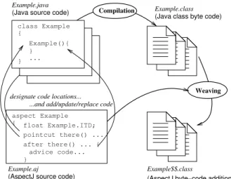
AspectJ is an extension to the Java language, that introduces two new constructs: A new unit of code, similar to the class construct, called an aspect, and a new syntax for the definition of pointcuts. In addition to the classical compile operation that produces the byte-code, AspectJ also requires a new code generation operation
Example.java aspect Example { } advice code... after there() ... { pointcut there() ... float Example.ITD;
...and add/update/replace code
Example$$.class
(AspectJ byte−code additions) Example.class
(Java class byte code) (Java source code)
class Example { } Example(){ } ... Example.aj
(AspectJ source code)
Weaving Compilation
designate code locations...
Figure 1: The weaving operation of AspectJ takes an aspect from a separate file and mixes the advices code with regular java byte-code at the particular locations defined using pointcuts and ITDs.
called weaving. As shown on Fig. 1, the weav-ing opearation mixes the code of the aspects with the regular code of the java classes. The particular code locations where this mixing hap-pens are designated using the pointcuts syntax; a single pointcut may designate multiple loca-tions at once. The modifications or additions made to the original code are called advices and are declared within the aspect code unit. An-other extension provided by AspectJ compared to normal Java, is the abaility to make Inter-Type Declarations (ITDs). An ITD extends an existing Java type with new content. For ex-ample, an ITD may add private attributes and accessor methods to an existing class.
Also worth noting, is the fact that the As-pectJ language and weaving toolchain are well supported and documented within Eclipse.
2.2 Which Concerns to Separate
In addition to the general concerns earlier men-tioned, such as persistence or access control, the particular concerns we might want to separate in M&S products are those related to the method-ology. For example, if we assume that we want to use simulation for a performance evaluation study, then we want to consider a fixed part that is unchanged in all the experiments, and a vari-able part that will change with each experiment. Then, the problem to solve is to be able to seam-lessly switch the variable part from one experi-ment to an another. In terms of concerns, this translates into the fact that we want to separate the fixed part, also referred to as the System Un-der Testing (SUT) from the variable part, also refered to as the Experimental Frame (EF)[10]. Classic approaches to operate this separation in a component-based model (eg. DEVS), involve relying on the component boundaries: The SUT is a central component, considered as a black-box, and the EF is a component or set of com-ponents connected to the external boundaries of the SUT. Unfortunately, this approach has the obvious limitation of preventing the EF from di-rectly reaching the core components of the SUT. This limitation disappears when using advanced SoC techniques such as Aspect Oriented Pro-gramming, which was introduced in previous sec-tion. For example, in a large computer network model, the components that model the services running on each node of the network might be deeply burried into the component hierarchy (eg. the application runs on a core that runs on a computer node that is part of a sub-network, and so on). However, for the needs of the ex-periment, it might be necessary to consider that this application needs to vary from one experi-ment to another and to place it under the control
of the EF. This could easily be achieved using AspectJ: A pointcut can designate the compo-nents that model the services and an advice can selectively replace or change the actual code of the service components everywhere deemed nec-essary in the model.
Another M&S concern that can be separated is the observation and instrumentation frame-work. Indeed, the data samples needed for each experiment are highly dependent on the experi-ment objectives. Without SoC, reusing the same model for various experiments requires either to over-sample (collect more data than strictly nec-essary so that the potential needs of all possible experiements are covered) or to change the code of the model for each experiment. The first case results in excessive use of computing and mem-ory resources and the second breaks the idea of reusing the same code, which is questionable in many cases, for example in a comparative study.
3
Shared Components
A hierarchical component model is a component model in which some components can be sub-components of others. In a hierarchical compo-nent model, a shared compocompo-nent is a compocompo-nent instance that can have more than one parent in the component hierarchy. In comparison with the well known Object Oriented terminology and design patterns, the concept of component shar-ing is close to that of a static class member or singleton pattern.
Indeed, sharing corresponds to the idea of making an alias or reference: Every time a com-ponent is shared, a reference is made to that ex-isting component, which results in the sharing of the component’s internal state. However, fol-lowing the component approach philosophy, the
internals of a component are hidden to other components and, therefore, the fact a component is shared is totally transparent to other compo-nents.
However, very few component models do ef-fectively support this sharing feature: the Frac-tal component model[1] does explicitly support sharing while some others, like JainSLEE[8] pro-vide proxying techniques which is a practical way of implementing sharing.
Hereafter, we describe three modeling pat-terns that illustrate the potential benefits of us-ing shared components in M&S:
• the proxy modeling pattern, described in section 3.1, helps to model the real connec-tions that may exist between components that are deeply buried within a component hierarchy;
• the shortcut modeling pattern, described in section 3.2, helps to establish shortcuts be-tween components in order to reduce the overall simulation complexity of the model; • the matriochka modeling pattern (Russian nested doll), described in section 3.3 helps to enforce layer separation and encapsula-tion in multi-layered architecture models.
3.1 The proxy modeling pattern
Let’s assume we want to model a road traffic net-work in which some of the vehicles are equipped with a wireless device, such as a PDA or a mobile phone.
If we also assume that we are using a component-based hierarchical approach and we want to model the fact that the device is part of the vehicle, then it should be a sub-component
wireless other interconnected elements network electronics vehicle road mechanics command wireless node
Figure 2: Model of a communicating vehicle including a radio network node that needs to cross the vehicle boundaries to reach the radio wireless network.
of the vehicles in which the device is placed, lo-cated for example in the electronics section of the vehicle.
However, as shown on Fig. 2, in order to plug the communicating device as a wireless node component in the vehicle, the latter needs to be modified to allow the wireless node to reach the wireless network (gray circled area).
These modifications make the task of reusing components more complicated. First, if we insert the same node model in many different vehicles, then all vehicle models need to be modified as shown in the grayed area. Second, if the compo-nents are deeply burried away from each other in the hierarchy, all the intermediate components that are on the way in the hierarchy need to be modified.
This modeling problem can be addressed using shared components. The use of such components following the proxy usage pattern is illustrated on Fig. 3. electronics command mechanics road vehicle wireless node wireless network interconnected elements other multiple places appears in same instance
Figure 3: Communicating vehicle of Fig. 2, with a shared component used as a proxy.
Thanks to sharing, the same wireless network component instance can appear multi-ple times in the model. Therefore, it is possi-ble to place the previous network shared com-ponent immediately beside the wireless node, within the vehicle’s electronics component. No-tice that in each vehicle component instance, we end up with a new (unshared) instance of the node component and a reused (shared) in-stance of the network component, enabling each node to be connected to the same network. The shared instance of the network component acts as a proxy between each of the node component instances. Nonetheless does this construction maintain the component design architecture (in-teractions between shared components and reg-ular component are required to follow the same protocol), but it actually results in a better en-capsulation, by preventing unnecessary interac-tions from propagating through the component hierarchy levels.
To summarize, the proxy modeling pattern is useful for modeling situations in which a given component (eg. the network) needs to be equally available in several places. In this case, the proxy
modeling pattern allows for such an extensive use of insertion without having to modify the target component. This greatly favors the reuse of existing components, because no modification are required on the surrounding components.
It is also worth stressing that we did not make any assumption on the dynamics of the modifi-cations: The problem addressed, thanks to the shared component in this proxy modeling pat-tern, would be exactly the same if the insertion of a the new component needed to be done once for all (the node is a fixed component of the ve-hicle) or dynamically during the simulation (the node is a component that may be plugged in and removed from the vehicle at any time).
3.2 The shortcut modeling pattern
The shortcut modeling pattern involves the use of a shared component in building interaction shortcuts between components. This construc-tion may be used to shorten the interacconstruc-tion path between multiple components, and hence reduce the simulation complexity of the model (see for example [10] for a definition of the simulation complexity).
It is worth stressing that, as opposed to to the previous proxy pattern, the main goal of this shortcut is to create an interaction that does not physically exist in the real system: It is a new, fake interaction that is only added in or-der reduce the simulation complexity. This kind of shortcut applies well to layered architecture, such as networks, in which peers at a given level would normally use the services of lower layers to communicate with each other instead of directly exchanging messages.
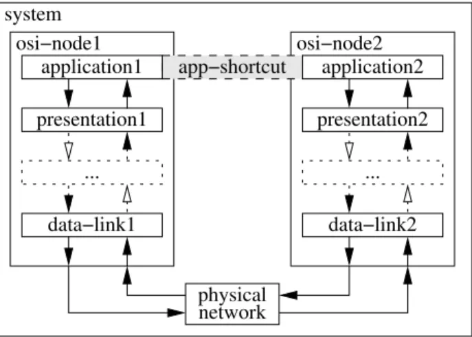
The result obtained by applying the shortcut modeling pattern is illustrated by Fig. 4 in which the shortcut is visualized by a dashed-line tunnel
presentation1 data−link1 ... physical network osi−node2 application2 presentation2 data−link2 ... system osi−node1 application1 app−shortcut
Figure 4: The shortcut modeling pattern applied between the application components of two OSI network nodes.
between the application1 and application2 components.
Such a construct makes sense if some of the traffic can be transfered to its destination through the shortcut while the remaining traffic continues to go through the normal route: Any traffic that can be simulated with negligible im-pact on the simulation results may go through the shortcut while the traffic that needs to be accurately simulated still goes through the usual path.
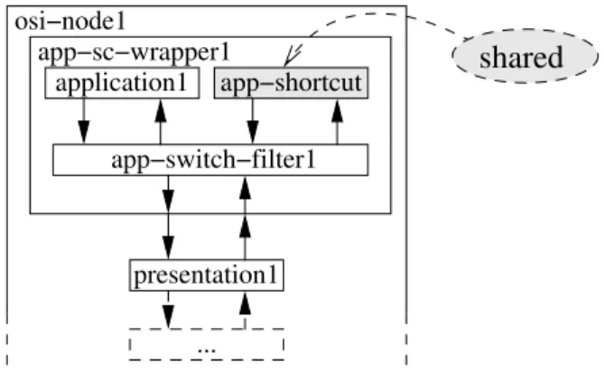
In order to build such a selective shortcut, the original application component model needs to be replaced by a new wrapper component, which is built as follows (example given for the osi-node1 side on Fig. 5):
• The original application component is reused without modification, and placed within the new wrapper component (it sends and receives the same traffic as in the original model);
• The original application component interac-tions (upstream/downstream arrows on fig-ure) are connected to a new filter compo-nent (named app-switch-filter1 on fig-ure), which is in charge of selecting which traffic goes through the shortcut and which traffic goes along the normal way;
• The previous switch component is con-nected on one side to the downstream route (toward the external component boundary and further to the presentation1 compo-nent), and on the other side, it is connected to the app-shortcut component;
• The app-shortcut component is equally shared by all instances of the new wrapper component: In our two-nodes example, the traffic that enters the app-shortcut from within the app-sc-wrapper1 component can be delivered to the app-switch-filter2 in the application wrapper of the osi-node2 and symetri-cally the traffic that enters the shortcut in osi-node2 can be delivered similarly through the shortcut to osi-node1.
Notice this shortcut pattern may be applied several times in the same model. Following the previous example, this means that similar short-cut tunnels could be built at each level of the OSI-layered model.
Therefore, this shortcut modeling pattern pro-vides a powerful means to adjust the simula-tion complexity of a model. However, deciding in which cases to use the shortcut path and in which cases it is not relevant is a difficult ques-tion because it strongly depends on both the model and the simulation goals. This question is still open to further research.
presentation1 application1 app−sc−wrapper1 osi−node1 app−switch−filter1 app−shortcut shared ...
Figure 5: The shortcut modeling pattern applied to the application layer component.
3.3 The matriochka modeling pattern
The matriochka (or Russian doll) modeling pat-tern applies to models of systems that exhibit a multi-level hierarchical structure. If we ignore the shortcut contruct, the OSI model depicted on Fig. 4 is a good example.
Despite the fact that this flat design reflects the usual layered representation of OSI-like mod-els, it actually does not reflect the hierarchical philosophy of the OSI-layered reference model in terms of components. Indeed, this flat de-sign violates (ignores) one of the fundamental principles of the layered approach[11]: An en-tity of level (N ) can only interact with entities of level (N + 1) and entities of level (N − 1). Indeed, despite the fact that no violation of this principle appears in the example in Fig. 4, the chosen design cannot help to prevent such a vi-olation: One could, mistakenly or on purpose, decide to connect the application component directly to the physical network component (provided that these two components have com-pliant interfaces).
presentation application
physical layer presentation
component
hierarchy OSI Layershierarchy application entity application presentation entity ... ... physical layer shared (MUST be)
(MAY be)
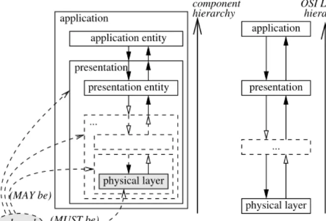
Figure 6: One of the two possible hierarchi-cal implementations of the simple OSI-Layered model, depicted in Fig. 4, that strictly enforces the OSI interaction policy.
modeling, a convenient way to fully enforce the fundamental principle of layer separation is to rely on the component hierarchy. For this, we have two options: Either we decide that the upper-most layer of the model (the application layer in the OSI model) is the outer-most com-ponent in the hierarchy or conversely (and para-doxically), we decide that the lower-most layer of the model (physical layer) is outer-most com-ponent in the hierarchy.
The first option is illustrated in Fig. 6: The left side of the figure represents the component hierarchy that implements the OSI-like layered hierarchy that is depicted on the right side of the figure. However, since each layer (except the lowest one) is implemented as a hierarchical com-ponent, new components have been introduced in order to distinguish the implementation parts of the layers (called entities in the figure) from their surrounding containers.
The difference between the previous solution
in Fig. 4 and the new solution depicted in Fig. 6 is that instead of having the component of layer (N ) laid beside the component of layer (N − 1), at the same level, we have the component of layer (N − 1) encapsulated inside the component of layer (N ).
Fig. 6 also clearly demonstrates why this ma-triochka modeling pattern benefits strongly from the sharing of components, since the actual in-teractions normally occur at the lowest (OSI-Layer) level. Therefore, we need some way of establishing connections between the inner-most physical layer components, which leads back to the proxy modeling pattern described in sec-tion 3.1.
Furthermore, Fig. 4 depicts a simplistic case of a more general interaction model in which the following patterns could also occur:
• the services provided by an entity of layer (N ) may be used by several upper entities of layer (N + 1) ;
• an entity of layer (N ) may be build on top of multiple services of layer (N − 1), each one possibly provided by multiple entities. Let’s consider the case of the first pattern above. Applied to the upper-most layer of our reference example, this pattern leads to a situation such as the one depicted on Fig. 7(a), where three application components use the same presentation component. Apply-ing the matriochka modelApply-ing pattern results in the situation depicted in Fig. 7(b), in which the presentation component is shared and in-serted at the same time in each of the three application components.
If we generalize the previous example to ev-ery possible level of our layered protocol stack,
appli1 appli2 appli3
presentation
...
(a) Flat layout without shared components
entity1appli appli1
presentation
entity2appli entity3appli
same shared component (hierarchical) appli2 presentation appli3 presentation ... ... ...
(b) Hierarchical layout with shared components
Figure 7: The matriochka modeling pattern ap-plied to the top layers of the OSI network model.
this means that for any layer (N ), the compo-nent entity (object instance) that implements the services of this layer (N ) may be shared sev-eral times amongst the entities of the upper layer (N + 1). The number of times the same entity is shared depends on the number of times enti-ties of layer (N + 1) need the services of layer (N ). Hence, this matriochka pattern strongly benefits from sharing because sharing allows for situations in which a component shared at the highest level can contain several sub-components that are shared themselves at the next level, and so on down to the bottom of the hierarchy.
4
Retry-on-error
incremental
development
An advanced M&S product needs to provide support for software development. Indeed, as shown in Part One, a typical simulation com-bines models, sampling policies, on-line compu-tations, experiment planning, visualization and possibly many more aspects. Even if some of the previous elements may come as ready-to-use libraries, supporting advanced simulation often requires the development of new elements, which inexorably leads to the selection of a software de-velopment life-cycle.
Well accepted development life-cycles usually go through the following steps: (i) requirement analysis, (ii) design, (iii) specifications, (iv) cod-ing, (v) unit testcod-ing, (vi) integration testcod-ing, and (vii) operational testing. A single iteration on these steps results in the so-called “V” life-cycle, while several iterations result in the so-called “spiral” life-cycle. Obviously, the spiral life-cycle offers more flexibility because it allows the devel-opers to make several attempts until they reach the final application design.
While this latter retry-on-error approach ap-pears useful for general purpose software, espe-cially for large software with unlcear require-ments, it turns to be even more interesting in an M&S development. Indeed, an important as-pect of experimental science, to which some of the simulation developments belong, is to be able to reproduce and augment existing experiments. Therefore, as soon as a simulation requires a de-velopment, this development becomes subject to later evolutions, either in the context of the same experiment maturation process, or in the context of a reuse process, as part of a new experiment. The developers of the Ruby-on-Rails
frame-work well understood the need for an efficient support of the retry-on-error process and spiral-like life-cycles. Indeed, not only do they provide active support for the various kinds of testing (steps (v) to (vii) mentioned above), but most importantly, they provide active support for it-erating many times throughout the full life-cycle. Recall that RoR is geared toward database de-velopment. Therefore, in RoR, the iterative sup-port must fully apply to the database design. This is achieved by providing a migration facil-ity as part of the framework. This migration is a mechnism that allows a RoR user (ie. a database software designer) to describe incre-mental changes that apply to the database at each iteration.
Even more interesting, this migration facil-ity is designed to be reversible: Each migration script contains an up section that describes how to change the database from iteration i to iter-ation i + 1, and a down section that describes how to revert back the database from configu-ration i + 1 to configuconfigu-ration i . Extensions to RoR, such as the Hobo plugin also discussed in the Part One of this paper, even provide an au-tomatic generation of the up and down sections through the detection of changes made to the application code.
Going back to the M&S application domain, a mechanism similar to the RoR migration could keep records of the successive changes made to simulation models and experiments. A minimal version of this incremental archival requirement could easily be fulfilled using a version track-ing system such as CVS, SVN or git. However, some additions are still required in order to keep track of the relationship between the incremen-tal changes made at the methodological level (eg. between simulation experiment i and simulation experiment i + 1) and the incremental changes
made to the software. Indeed, the cases in which the experimental history happens to follow ex-actly the historical path of the software develop-ments should be considered exceptional.
Therefore, the lessons learned from RoR is that, even in the difficult case of a database, ways can be found to keep track of incremen-tal changes made to the application. A remark-able consequence is that, since this feature is fully supported by RoR, the whole methodology of development is positively changed: instead of being forced to achieved a perfect design before the coding phase has started, which is always a challenge, the development can proceed by suc-cessive incremental steps and follow a retry-on-error approach. Undoubtedly, this retry-on-retry-on-error incremental approach would suit well the needs of M&S products, especially when used to sup-port experimental science, because the research directions are often subject to changes. Hence our suggestion to retain this idea when develop-ing a new M&S product.
5
Conclusion
In this two-part article, we first illustrated that building a new M&S product does not neces-sarily require starting a new development from scratch. On the contrary, in Part One, we showed that existing general purpose software can provide many of the functions required to support M&S developments. Then, in Part Two, assuming development from scratch is still going to be popular for a long time, we described how some of the ideas found in the previous existing solutions are worth borrowing.
Therefore, from the conclusions of Part One, we may deduce that it is possible to reuse (ex-isting) products of Software Engineering (SE))
in order to build new M&S software products. However, although not contradictory with the previous ones, the conclusions of Part Two did demonstrate that borrowing good ideas from ex-isting products and using latest SE techniques will still produce good simulation products.
As usual when two reasonable solutions ex-ist, the perfect answer is probably somewhere in the middle: SE products should be reused as much as possible to save development costs and to benefit from the boosted support of an ex-isting community. Nevertheless, this should not preclude designers from starting some new devel-opments from scratch using latest SE techniques and ideas when this is expected to significantly improve the product.
These ideas and principles have actually been experimented and tested with success by the au-thor in an open source project called Open Sim-ulation Software (OSA)1. Indeed, OSA serves both as an experimental platform for new ideas and as a M&S support software. For instance, OSA already relies on FCM components for modeling and experiment design, on Eclipse for its user interface, on Maven for the project management and it uses Aspect Oriented Pro-gramming techniques such as AspectJ. OSA can be used with third-party simulation engines (such as the JAMES II DEVS engine and re-lated plugins[6]), provides distributed execution support and shared components, and fully im-plements SoC principles to separate modeling, instrumentation and Experimental Frame con-cerns. Interested readers can find more informa-tion about some of these experiments and related features in these publications: [2, 3] about using FCM for building a new component-based M&S product, [4, 9] about applying SoC to M&S, and
1http://osa.inria.fr/, http://osa.gforge.inria.fr/
[5] about shared components.
ACKNOWLEDGMENTS
This work is partly funded by the French Agence Nationale de la Recherche (ANR), in the USS-SimGrid project and partly by INRIA, in collab-oration with the University of Carleton, in the context of the Associated Team DISSIMINET.
References
[1] E. Bruneton, T. Coupaye, and J.B. Stefani. The fractal component model specification. Available from http://fractal.objectweb.org/specification/, February 2004. Draft version 2.0-3.
[2] Olivier Dalle. Component-based dis-crete event simulation using the fractal component model. In AI, Simulation and Planning in High Autonomy Systems (AIS)-Conceptual Modeling and Simulation (CMS) Joint Conference, Buenos Aires, AR, Februray 2007.
[3] Olivier Dalle. The OSA Project: an Ex-ample of Component Based Software Engi-neering Techniques Applied to Simulation. In Proc. of the Summer Computer Simula-tion Conference (SCSC’07), San Diego, CA, July 15-18 2007. Invited Paper.
[4] Olivier Dalle and Cyrine Mrabet. An In-strumentation Framework for component-based simulations component-based on the Separation of Concerns paradigm. In Proc. of 6th EU-ROSIM Congress (EUEU-ROSIM’2007), Ljubl-jana, Slovenia, September 9-13 2007.
[5] Olivier Dalle, Bernard P. Zeigler, and Gabriel A. Wainer. Extending DEVS to support multiple occurrence in component-based simulation. In S. J. Mason, R. R. Hill, L. Moench, and O. Rose, editors, Proceed-ings of the 2008 Winter Simulation Confer-ence, December 2008.
[6] J. Himmelspach and A.M. Uhrmacher. The JAMES II Framework for Modeling and Simulation. In 2009 International Work-shop on High Performance Computational Systems Biology, pages 101–102. IEEE, 2009.
[7] G. Kiczales, J. Lamping, A. Mendhekar, C. Maeda, C. Videira Lopes, J.-M. Lo-ingtier, and J. Irwin. Aspect-oriented pro-gramming. In European Conference on Object-Oriented Programming, ECOOP’97, volume 1241 of LNCS, pages 220–242, Jyv¨askyl¨a, Finland, June 1997. Springer-Verlag.
[8] Swee Boon Lim and David Ferry. Jain SLEE 1.0 Specification. Sun Microsystems Inc. & Open Cloud Ltd., 2002.
[9] Judicael Ribault and Olivier Dalle. En-abling advanced simulation scenarios with new software engineering techniques. In 20th European Modeling and Simulation Symposium (EMSS 2008), Briatico, Italy, 2008.
[10] B. P. Zeigler, H. Praehofer, and T. G. Kim. Theory of Modeling and Simulation. Aca-demic Press, 2nd edition, 2000.
[11] Hubert Zimmerman. OSI Reference Model– The ISO Model of Architecture for Open
Systems Interconnection. IEEE Transac-tions on CommunicaTransac-tions, COM-28(4):425– 432, April 1980. (Invited paper).
AUTHOR BIOGRAPHIES
Olivier Dalle is Maˆıtre de Conf´erences in the Computer Science department of the Faculty of Sciences at the University of Nice-Sophia Antipolis (UNS). He received his B.Sc. from the University of Bordeaux 1 and his M.Sc. and Ph.D. from UNS. From 1999 to 2000, he was a postdoctoral fellow at the French Space Agency center in Toulouse (CNES-CST), where he started working on component-based discrete-event simulation of multi-media telecommunication systems. In 2000, he was appointed by UNS, and he joined the MAS-COTTE research group, a joint team of UNS, CNRS and INRIA. His current research interests in discrete-event simulation are on methodology support, very large-scale networked systems, and wireless communication systems. His email address is [email protected].