HAL Id: hal-02114145
https://hal-amu.archives-ouvertes.fr/hal-02114145
Submitted on 29 Apr 2019
HAL is a multi-disciplinary open access
archive for the deposit and dissemination of
sci-entific research documents, whether they are
pub-lished or not. The documents may come from
teaching and research institutions in France or
abroad, or from public or private research centers.
L’archive ouverte pluridisciplinaire HAL, est
destinée au dépôt et à la diffusion de documents
scientifiques de niveau recherche, publiés ou non,
émanant des établissements d’enseignement et de
recherche français ou étrangers, des laboratoires
publics ou privés.
Impact of the plasma geometry on divertor power
exhaust: experimental evidence from TCV and
simulations with SolEdge2D and TOKAM3X
Alberto Gallo, Nicolas Fedorczak, Sarah Elmore, Roberto Maurizio, Holger
Reimerdes, Christian Theiler, Cedric Tsui, Jose Boedo, Michael Faitsch, Hugo
Bufferand, et al.
To cite this version:
Alberto Gallo, Nicolas Fedorczak, Sarah Elmore, Roberto Maurizio, Holger Reimerdes, et al.. Impact
of the plasma geometry on divertor power exhaust: experimental evidence from TCV and simulations
with SolEdge2D and TOKAM3X. Plasma Physics and Controlled Fusion, IOP Publishing, 2018, 60
(1), pp.014007. �10.1088/1361-6587/aa857b�. �hal-02114145�
Impact of the plasma geometry on divertor
power exhaust: experimental evidence from
TCV and simulations with SolEdge2D and
TOKAM3X
A Gallo
1, N Fedorczak
1, S Elmore
2, R Maurizio
3, H Reimerdes
3,
C Theiler
3, C K Tsui
3,4, J A Boedo
4, M Faitsch
5, H Bufferand
1,
G Ciraolo
1, D Galassi
6, P Ghendrih
1, M Valentinuzzi
1, P Tamain
1,
the EUROfusion MST1 team
7and the TCV team
81
IRFM, CEA-Cadarache, F-13108 Saint-Paul-lez-Durance, France
2
CCFE, Culham Science Center, Abingdon, OX14 3DB, United Kingdom
3
Swiss Plasma Center(SPC), Ecole Polytechnique Fédérale de Lausanne (EPFL), CH-1015 Lausanne, Switzerland
4
University of California-San Diego, La Jolla, CA 92093, United States of America
5
Max-Planck-Institute for Plasma Physics, Boltzmannstr. 2, D-85748 Garching, Germany
6
Aix Marseille Univ, CNRS, Centrale Marseille, M2P2, Marseille, France E-mail:alberto.gallo@cea.fr
Abstract
A deep understanding of plasma transport at the edge of magnetically confined fusion plasmas is needed for the handling and control of heat loads on the machinefirst wall. Experimental observations collected on a number of tokamaks over the last three decades taught us that heat flux profiles at the divertor targets of X-point configurations can be parametrized by using two scale lengths for the scrape-off layer(SOL) transport, separately characterizing the main SOL (lq) and the divertor SOL (Sq). In this work we challenge the current interpretation of these two
scale lengths as well as their dependence on plasma parameters by studying the effect of divertor geometry modifications on heat exhaust in the Tokamak à Configuration Variable. In particular, a significant broadening of the heat flux profiles at the outer divertor target is diagnosed while increasing the length of the outer divertor leg in lower single null, Ohmic, L-mode discharges. Efforts to reproduce this experimentalfinding with both diffusive (SolEdge2D-EIRENE) and turbulent(TOKAM3X) modelling tools confirm the validity of a diffusive approach for simulating heatflux profiles in more traditional, short leg, configurations while highlighting the need of a turbulent description for modified, long leg, ones in which strongly asymmetric divertor perpendicular transport develops.
Keywords: scrape-off layer transport, divertor magnetic geometry, heat load characterization (Some figures may appear in colour only in the online journal)
1. Introduction
1.1. Heat flux limit on plasma facing components
The successful and safe operation of future magnetic con-finement nuclear fusion reactors like ITER strongly depends
7 See the author list of H Meyer et al 2017 Nucl. Fusion57 102014. 8
on overcoming several currently open issues in the fields of physics and technology. An efficient and controlled handling of the power exhaust is one of them. In diverted con figura-tions, during the steady state, part of the power supplied to the confined plasma by the heating systems is transferred to the scrape-off layer (SOL): here unconfined plasma flows towards the vacuum vessel walls both along and transversely to open magneticfield lines. Most of the exhausted heat and particle flux is concentrated onto dedicated components, called divertor targets. Such components, which in ITER will be made out of tungsten, can tolerate a heatflux normal to the material surface up toqsurf =10 MW m-2in steady state and of20 MW m-2 during slow transients[1]. These limits refer
to pristine, undamaged, tungsten and might have to be cor-rected when taking into account the effect of plasmafluence and modifications of the divertor design, as recently shown in [2–4]. It should be noted that, in order to limit qsurf, ITER will have to be operated in partially detached conditions [5]. Detached plasmas are beyond the scope of this work, which focuses entirely on attached conditions. A detailed study of the effect of plasma geometry on detachment can be found in [6]. For a given power Pdivflowing towards the outer divertor
target, the maximum heatflux is determined by the wetted area: Pdiv=Awet surfqmax2p lRt wet qsurfmax, where Rt is the
position of the target along the tokamak major radius andlwet
is the wetted width, equivalent of Awet once toroidal
sym-metry is assumed. Such quantity depends on the width of the SOL which in turn is determined by plasma transport in the boundary region.
1.2. Width of the SOL
When talking about the width of the SOL we refer to the distance from the magnetic separatrix over which plasma quantities such as density n, temperature T and heatflux q are spread on open magnetic field lines. Such width can be understood as a result of the competition between transport parallel(P) and perpendicular (⊥) to the total magnetic fieldB
[7]. In a particle description, when the plasma reaches the divertor targets, it has spent as much time travelling in theP as in the⊥ direction: t=t^. This can be rephrased, in terms of
distances and velocities, asL v =lSOL v^, whereLis the
parallel connection length(length of field lines from the outer midplane to the target), lSOL is the SOL width,v and v^are the velocities in the P and ⊥ direction respectively. Since plasma transport is much quicker along field lines than transversely because of confinement, lSOL is expected to be
much smaller thanL . A simpli fied picture of SOL transport
can be obtained assuming that plasma travels at sound speed
cs along field lines while diffusing in the ⊥ direction:
lSOL= D L c^ s, whereD m s^[ 2 -1]is the particle
diffusiv-ity in the⊥ direction. A more sophisticated description would require an expression forv^ based on, for instance, turbulent
arguments. The notation used so far was intentionally generic since n T, and q might be transported at different speed and therefore their profiles could be characterized by different widths. Although the main focus of this work will be on the heatflux width lq, its link with the density and temperature
widths, ln and lT respectively, are important matter for
discussion.
1.3. Parametrization of SOL profiles
In order to assess their widths, one has to efficiently para-metrize radial profiles of SOL quantities. Such profiles have different shape at different poloidal locations since diverse are the source and sink terms at play. As sketched infigure1, the SOL is conventionally divided in(1) the main SOL, above the X-point and surrounding the main plasma, and(2) the divertor SOL, below the X-point and further separated in private (PFR) and common (CFR) flux region. In the main SOL the plasma core represents the source of particles and heat: here the SOL width is a balance betweenP transport towards the divertor and ⊥ transport towards the vessel wall, both acting as sinks. This yields, for a generic SOL quantity y, exponentially decaying radial profiles of the form:
l = ⎛ -⎝ ⎜ ⎞ ⎠ ⎟ ( ) ( ) y r y r f exp , 1 y 0 x
where y0is the separatrix value,r=(R -Rsep omp) ·fx 0is
the radial distance from the separatrix, fxis the local magnetic flux expansion [8] and the decay length ly approximates the SOL width. In the divertor SOL, instead, the plasma from the main SOL enters the CFR and is lost perpendicularly on either side, towards the vessel wall and in the PFR. This corresponds to a diffusion of the main SOL profiles in the ⊥ direction, with two consequences: (i) profiles get broader, increasing the wetted width at the targets, and (ii) the peak gets lower and shifts away from the magnetic strike point in the CFR as a result of the roll-over in the PFR[9]. Under these hypotheses, divertor profiles can be described by the convolution of a Figure 1.Sketch of a diverted configuration showing plasma core
(purple), separatrix (black solid line), a generic SOL ψ surface (thick black dashed line), main SOL (white), CFR (white), PFR (green), divertor target(grey), inner and outer strike points (ISP and OSP, yellow), plasma fluxes parallel and perpendicular to magnetic ψ surfaces(red and blue arrows).
decaying exponential with a Gaussian[10]: l l l = ⎛ - - + ⎝ ⎜⎜⎛⎝⎜ ⎞ ⎠ ⎟ ⎞ ⎠ ⎟⎟ ⎛⎝⎜ ⎞ ⎠ ⎟ ( ) ( ) 2 y r y S r f S r S f y 2 exp 2 erfc 2 , y y y y y y 0 2 x x bg
where Syis the width of the Gaussian called spreading factor
and ybg is the background value. Negative values of r refer to the PFR. Assuming that trivial details of the magnetic geo-metry(flaring of flux surfaces and their tilting with respect to divertor targets) can be removed through fx, by definition ly and Sy represent the scale lengths of main SOL and divertor
transport respectively. Concerning the heatflux, for example, both lq and Sq, as well as of course fx, will concur setting the
overalllwet at the target. A good estimate of this quantity can
be given through the so-called integral width[8]:
ò
l = l = -( -( ) ) ( ) f f q r q r q q d 3 wet x int x bg max bgwhich directly links the profile width with qmax that has to respect the material constraints discussed in section 1.1. In particular, for profiles that can be described with equation (2), it is possible to approximate lintl +q 1.64Sq [11].
1.4. Scaling laws and extrapolation to ITER
In order to understand the physics governing the heat flux width and to make predictions for future devices like ITER, one can look for dependencies of lqand Sqon plasma control
parameters(toroidal magnetic field BT, poloidal magneticfield
BP, plasma current IP, edge safety factor q95, power entering
the SOL PSOL, major radius R0, etc.) in existing devices to
create scaling laws. With this purpose, a multi-machine data-base was built using target heat flux profiles measured with infrared(IR) thermography during attached H-mode discharges in tokamaks with D-shaped section (JET, AUG, DIII-D and C-mod) as well as spherical ones (NSTX and MAST). Regression of control parameters identified that the most sig-nificant dependency is the one on BP at the outer midplane:
l = B
-0.64
q P,omp1.15 [12]. This scaling law predicts a very small
value of l = 1 mmq for the foreseen ITER IP=15 MA
scenario. Heat load studies of attached L-mode discharges in JET and AUG[13] showed that lqL mode‐ 2lqH mode‐ and has a similar dependence on control parameters. The existence of such a common trend among tokamaks with different vessel shape and aspect ratio would suggest that, if lqdepends on any machine-specific feature like, for instance, the magnetic geo-metry of the divertor, this dependence is weak compared to the one on BP,omp. This would be coherent with its definition of
main SOL quantity given in section1.3. The trend of lqwith
BP,omp(an therefore with IP, if minor radius a and elongation k
are constant) has been reproduced qualitatively by a turbulent model based on blob measurements in L-mode limited dis-charges in the Tore Supra tokamak[14], as well as in num-erical simulation of the edge and SOL turbulence in MAST performed with the ESEL code [15]. Multi-machine scaling laws for limited discharges can be found in[16]. Even though
the value of lq in limited discharges can differ from diverted ones, these results confirm the generality of such feature and underline the importance of lowfield side turbulence localized around the outer midplane [17] in setting lq. On the other hand, a cross-machine trend of Sqis yet to be found. A scaling
law for Sqwas found for attached L-mode discharges in AUG,
highlighting a strong dependence on divertor conditions as electron temperature Te and density ne [18]. According to
recent experiment on TCV, Sq is also insensitive to fx [19].
Bothfindings suggest that Sq, as discussed in section1.3, is a
divertor quantity and therefore work needs to be done tofind common trends among different machines.
With the aim of testing the hypothesis that main SOL and divertor transport can be described with two separated scale lengths, a dedicated experiment, detailed in section 2, was carried out on the TCV tokamak: lq and Sqwere estimated
while scanning the length of the outer divertor leg in L-mode, lower single null (LSN), Ohmic discharges. Experimental findings are compared with different philosophies of transport code simulations (MONALISA [20], SolEdge2D-EIRENE [21], TOKAM3X [22, 23]) in section 3 to discriminate, among possible mechanisms, the physics responsible for the experimental trends. Section 4 is dedicated to interpretation while section5summarizes the conclusions.
2. Experiment
2.1. Motivation
To understand whether lqis truly insensitive to the magnetic geometry and try to find a scaling parameter for Sqare two
separate goals that might be achieved within a single experiment. If it was possible to significantly change the size of the divertor while keeping all core plasma parameters constant, according to the aforementioned interpretation, one would expect not to see a variation in lq while Sq could
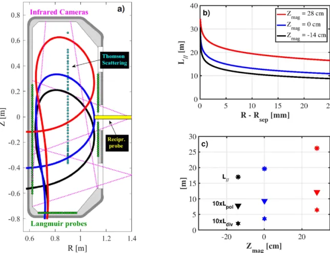
effectively increase due to the bigger divertor volume. Most of the tokamaks have limited flexibility in changing the magnetic equilibrium. An exception is represented by the Tokamakà Configuration Variable (TCV). With its elongated vacuum vessel surrounded by 16 independent poloidal field coils, TCV has very good shaping capabilities[6] making it a valuable candidate for this study. The device also benefits from a wide set of edge diagnostics(figure2(a)): main plasma conditions(neu and Teu) in the core, edge and SOL are
mon-itored with an high resolution Thomson scattering (HRTS) [24] and a reciprocating Langmuir probe (RCP) plunging at the outer midplane [25]. Plasma conditions at the divertor targets (net and Tet) are assessed with wall-embedded
Lang-muir probes(LP) [26], while profiles of the heat flux on the target qsurft are obtained via the IR thermography system[19].
2.2. Strategy
A shot-to-shot scan of the vertical position of the magnetic axis (Zmag) was performed in LSN, Ohmic, L-mode, low density
(fGW =n nGW25% 30%– , where nGW =IP pa2 is the
fixed main plasma shape (R0=89 cm,a=22 cm,k=1.4). Ohmic H-mode discharges are not considered in this work. Plasmas at vertical positionZmag= -14, 0 and 28 cm, pic-tured in figure 2(a), were achieved at constant B0=1.4 T, constantIP210 kAand therefore constantBP,omp0.18 T.
Changing Zmagleads to a variation of LPfrom the outer
mid-plane to the outer target, whose radial SOL profiles are shown in figure 2(b). The values of LP (17 m, 19.6 m and 26.2 m respectively, averaged over a 5 mm distance from the magnetic separatrix), are displayed in figure2(c), together with those of poloidal connection length Lpol (0.77 m, 0.93 m and 1.21 m
respectively). These three vertical plasma positions correspond to a divertor leg length Ldiv (vertical X-point to outer target
distance) of 21, 36 and 64 cm. Each of these quantities increases linearly with Zmag and therefore they give an
equivalent description. In the following Ldiv will be used and
we will refer to these configurations also as short, medium and long leg, respectively. The main deliverable of the experiment is the assessment of the effect of Ldiv on main plasma and
target profiles of n Te, eand electron heatflux qefrom LP and
RCP, as well as on target q profiles from IR. All discharges used in this dataset are characterized by a variation of core line averaged density ne,av
coreand of q
95within 10%. Every discharge
consists of a 500 ms steady phase in which the magnetic equilibrium is kept as still as possible to help IR measurements,
followed by a sweeping phase of few hundreds of ms in which the divertor leg is moved across different LP to improve the spatial coverage of time-integrated ne,Teand qetarget profiles.
2.3. Upstream plasma conditions
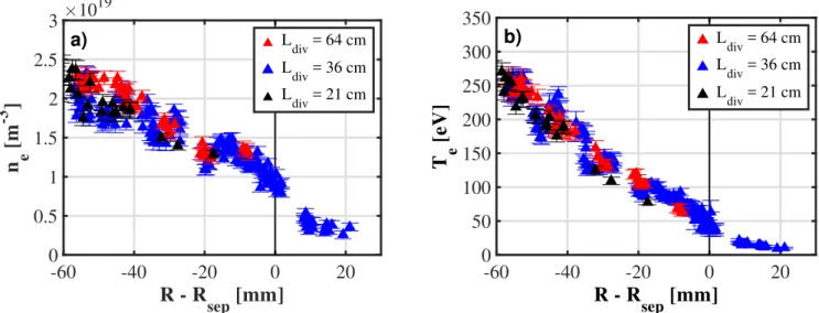
Measurements of the core and edge plasma properties with HRTS show that, when changing Ldiv and therefore LP, there
is no significant impact on ne and Te (figure 3). This result
suggests that the goal of matching main plasma conditions, while changing the divertor geometry, was achieved. Due to the sensitivity of Thomson scattering channels in the edge region, experimental data in the main SOL are available only for plasmas with medium divertor leg. When comparing tar-get to main SOL profiles for the different values of Ldiv we
take as working assumption that, given the good match in the core and edge, ne and Te match also in the main SOL. In
figures 4(a) and (b) respectively, outer midplane measure-ments of ne and Te performed with a reciprocating double
probe system[25] (RCP, green diamonds) are superimposed to target profiles from wall LP (blue dots) for the medium leg configuration. Outer midplane and target density profiles are in good agreement, suggesting no strong variation of ne in
terms of peak value nor of decay length along LP. On the other hand Te drops on average by a factor of 2,
Figure 2.(a) Cross section of the TCV vacuum vessel with main diagnostics. Magnetic separatrix for short, medium and long outer divertor
leg configurations in black, blue and red. (b) Profiles of the SOL parallel connection length from outer midplane to outer divertor target. (c) Parallel connection length(stars), poloidal connection length (triangles) and vertical X-point to target distance (hexagons) as a function of vertical position of magnetic axis.
indicating that the static pressurePe=n Te eis not conserved
along the outer SOL. If one instead considers the total pres-surePe* =n Te e(1+M2)and assumes M=1 ( =v cs) near
the target, according to the Bohm criterion, conservation is fulfilled: *Pe =2n T P* =n T ,t e t e t e ,u e u e
u. This result suggests
that, at the outer target, the plasma is in attached condition.
2.4. Target plasma conditions
The wall LP system for the outer divertor target consists in a single array of 26 cylindrical domed probes protruding by 1 mm, with a diameter of 4 mm and a spatial resolution of 11 mm [26]. The acquisition is sampled at 500 kHz and I–V characteristics are averaged over 50 ms, shorter than the frequency at which the magnetic strike point is swept across two neighbouring probes. A four parametersfit is performed on the I–V characteristics, to account for the sheath expansion in the saturation current branch. LP measurements show an effect of the divertor magnetic geometry on ne,Te and qe:
width, shape and amplitude of the outer target profiles change with the length of the outer divertor leg. For the sake of readability, all shown profiles are obtained binding data from three to four discharges repeated for the same value of Ldiv
and in similar conditions: markers represent the average value of each dataset, error bars the corresponding standard devia-tion. Profiles of n Te, e and qeare plotted as a function of the
radial distance from the magnetic separatrix( -R Rsep) at the
outer midplane: it should be remembered that LP profiles are measured at the divertor target and then remapped at the outer midplane along magneticflux (ψ) surfaces in order to allow the comparison of magnetic equilibria with different fx. A
least squarefit to equation (2), represented by the solid lines, is performed to estimate the transport scale lengths (l Sy, y): here markers represent the value obtained byfitting the whole dataset for a given condition, without binding the data, while error bars correspond to the accuracy of thefit.
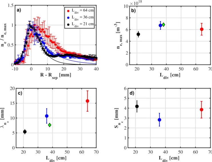
Figure5(a) shows neprofiles normalized to their maximum
value to help visualizing shape variations. The information about Figure 3.Thomson scattering, main plasma, profiles of (a) neand(b) Teas a function of the radial distance from the outer midplane separatrix
forLdiv=21 cm, 36 cm and 64 cm(black, blue and red triangles respectively).
Figure 4.Outer midplane, reciprocating Langmuir probe(green diamonds) and outer target Langmuir probes (blue circles) profiles of (a) ne
the corresponding peak value is given infigure 5(b):ne,max=
´ - ´
-5.2 1018m , 6.73 1018 m 3 and 6.1´1018 m-3
corre-spond to 18%, 23% and 21% of ne,avcore respectively, indicating
similar core-to-target drop regardless of the divertor leg length. For the medium leg configuration, the value of ne,max is
con-sistent with the one at the separatrix, nesep, measured by the RCP
at the outer midplane(green diamond) meaning that no density drop occurs along the outer SOL. These results suggest that there is not a strong effect of Ldiv on the density peak value. If one
instead considers width and shape of the profiles, the impact of changing the divertor geometry is stronger: a monotonic trend of the density decay length lne with Ldiv (figure5(c)) is detected, with a factor of 3 increase over the explored range. The value oflne for the medium leg configuration is 1.4 times bigger than the one measured by the RCP at the outer midplane(green diamond), suggesting that a broadening of the density profile occurs on the path from the outer midplane to the target. The density spreading factor Sne (figure 5(d)) shows no trend with
Ldiv, with values in the range from 2.5 to 4.5 mm.
Inter-estingly the main SOL transport scale length lnehas a stronger relative variation than the divertor one Sne, when increasing the outer divertor leg length. It should be noted that neprofiles for
the short and medium leg configurations exhibit an asymmetric background, which is non null in the far CFR. These shoulders, unlike the density-dependent ones observed for instance in [28,29], correspond to positions on the outer divertor target that are not seamlessly connected to the inner divertor target since magneticfield lines intercept the vacuum vessel either at the top of the machine or at the outer wall. For this reason, such locations are not taken into account in the fitting procedure, which was performed up to R-Rsep =10 mm and 15 mm for short and medium leg, respectively.
Figure6(a) shows the corresponding normalized target Te
profiles. Unlike density, Teexhibits a clear drop in peak value
and a less marked broadening of profiles (at least in the CFR) with increasing Ldiv. In fact, the peak value Te,max(figure6(b))
is reduced by a factor of 2 with Ldiv, from 20.3 to
11.2 eV. The value for the medium leg configuration (17.8 eV) corresponds to 40% of Te
sepmeasured by the RCP
at the outer midplane (green diamond) indicating a Te drop
along the SOL. The target temperature decay lengthlTe, whose values are in the range 20–35 mm, is not straightforwardly affected by Ldiv, as no trend stands out of the error bars
Figure 5.(a) Normalized outer target Langmuir probes profiles of neas a function of radial distance from the outer midplane separatrix for
short, medium and long outer divertor leg configurations in black, blue and red. Density (b) peak value, (c) decay length and (d) spreading factor as a function of outer divertor leg length. Green diamonds for outer midplane reciprocating Langmuir probe data.
(figure 6(c)). The value for the middle configuration is 3 times bigger than the one measured by the RCP (green dia-mond), suggesting a strong broadening of the Teprofile along
the outer SOL. Unlike lTe, the temperature spreading factor STe changes monotonically with Ldiv (figure6(d)), with a factor of
2 to 5 increase between short and long leg configurations, within the big error bar of the latter. This would mean that, for temperature, a very long divertor leg has a stronger effect on the divertor transport scale length than on the main SOL one. Finally the corresponding qeprofiles are shown in figure7(a), where a clear broadening with Ldivcan be detected. With qe,max
values of 184.8 kWm-2, 260.4 kW m-2 and 87.4 kW m-2
respectively, a factor of 2 drop between short and long leg configurations is measured (figure7(b)). These data correspond to 60% of the heat flux measured by the IR thermography (empty squares) [19], which is the total heat flux absorbed by the target and therefore comprehends not only the electronic component but also the ionic one as well as radiation. According to standard sheath theory, the heat flux can be estimated from LP data asq=gkTe eG = gkT n ce e s, whereγ is
the sheath heat transmission coefficient. If equally important
contribution from electrons and ions is assumed( =Ti Te), then
one should take g = 8[7]. Given that the assumption of =Ti 0 was made(g = 5, electron heat flux only), such difference is consistent with the 5 860% discrepancy between LP and IR. The heat flux decay length lqe (figure 7(c)) undergoes a factor of 2 increase with Ldiv which is consistent with lq
IR
(empty squares). The value measured for the medium leg configuration is 1.4 times larger than the corresponding lqRCP
e measured at the outer midplane (green diamond) suggesting that, besides flux expansion and divertor spreading, the heat flux profile broadens along the outer SOL. For the heat flux spreading factor Sqeinstead, no trend can be detected within the sensibility of the two diagnostics(figure7(d)). Here values are in the range of 2–3 mm and, especially for the long leg con-figuration, error bars are comparatively big. To summarize, according to LP measurement, a longer divertor leg causes the broadening of qe profiles and the corresponding drop of the peak value. Interestingly, as observed for ne profiles, both
diagnostics highlight a stronger variation of the main SOL transport scale length lqcompared to the divertor one Sqwhen
modifying the divertor geometry.
Figure 6.(a) Normalized outer target Langmuir probes profiles of Teas a function of radial distance from the outer midplane separatrix for
short, medium and long outer divertor leg configurations in black, blue and red. Temperature (b) peak value, (c) decay length and (d) spreading factor as a function of outer divertor leg length. Green diamonds for outer midplane reciprocating Langmuir probe data.
3. Modelling of SOL transport
This section concerns the modelling of the aforementioned divertor leg experiment. Different codes including different physics, based on different assumptions have been employed. The results point out that the key to capture the different features of the effect of divertor geometry on SOL quantities, with focus on heatflux profiles, is the assumed degree of (dis)homogeneity of transport. Thefirst attempt consists in using diffusive models with uniform transport coefficients in the whole simulation domain. Then a radial dependence D r^( ),c^( )r , arbitrary or
inferred from experimental measurements, can be assumed. A step further consists in modelling the so-called ballooned transport in which perpendicular transport is enhanced in the surroundings of the outer midplane: this can be done with transport coefficients that change also in the poloidal direction:
q c q
^( ) ^( )
D r, , r, . Last and more complex approach is to use a first principle turbulent model in which particle fluxes are cal-culated self-consistently and therefore the corresponding effec-tive perpendicular transport coefficient would differ from point to point in the simulation domain:D^,eff(R Z, ).
3.1. Homogeneous perpendicular transport
A simple approach to the modelling of SOL transport is to assume that the plasma travels mainly in the parallel direction while undergoing diffusion in the perpendicular one. These are the basic assumptions of MONALISA [20], a Monte Carlo code in which energy packets with parallel velocity v=cs
from a Maxwellian distribution of width T freely stream along
Bwhile diffusing perpendicularly under an arbitrary coefficient
^
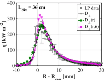
D which is uniform in the entire domain of the simulation. Although the physics of transport is as simple as it can possibly get, featuring the real magnetic geometry from experimentalψ maps and the actual tokamak wall, MONALISA can well reproduce experimental q profiles, as demonstrated by the black solid line infigure8, where numerical and experimental profiles for the medium leg configuration are superimposed. Attempts to model the divertor leg experiment with such code give mixed results: simulations with different Ldiv at constant
= = =
^
-D 0.5 m s ,2 1 T 40 eV, I 210 kA
P andBT=1.4 T,
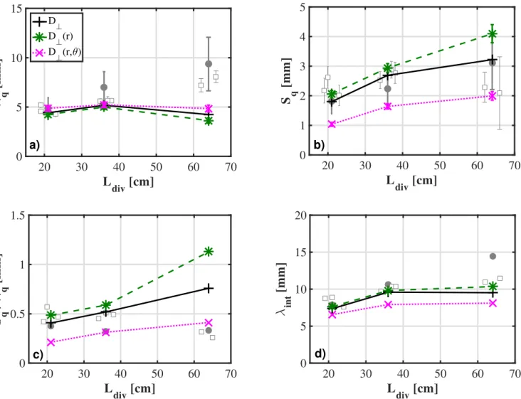
show no increase in lq (figure9(a), solid black line) while a monotonically increasing Sq is predicted (figure 9(b)).
Inter-estingly, MONALISA results fit well to IR experimental data Figure 7.(a) Normalized outer target Langmuir probes profiles of qeas a function of radial distance from the outer midplane separatrix for short, medium and long outer divertor leg configurations in black, blue and red. Heat flux (b) peak value, (c) decay length and (d) spreading factor as a function of outer divertor leg length. Empty squares for target infrared data. Green diamond for outer midplane reciprocating Langmuir probe data.
(squares) forLdiv=21and 36 cm, but the factor of 2 increase in lqforLdiv=64 cm, as well as the non monotonic trend for
Sqcannot be captured. This leads, for the latter configuration,
to a strong overestimation of the ratioSq lq(figure9(c)) which is an indicator of the degree of asymmetry: when Sq lq approaches 1, profiles become Gaussian-like while in experi-ments(Sq l =q 0.3) they are much steeper on the PFR side than the CFR one. Simulations performed with the more sophisticated SolEdge2D-EIRE code package, described in section 3.2, assuming constant transport coefficients, yield trends in qualitative agreement with MONALISA: lq is con-stant with Ldivwhile Sqincreases monotonically. Even though,
in this kind of simulations, the values of the two scale lengths do not match the experiment for the long leg case, and there-fore the information about the relative importance of radial transport in the main SOL and divertor SOL cannot be extracted, it is worth noting that lint is in good agreement
(figure 9(d)). This result suggests that, even for modified divertor geometries, this model can still give a good indication about the average width of heatflux profiles.
3.2. Radially dependent perpendicular transport
A more sophisticated approach consists in assuming that perpendicular transport coefficients, and therefore the corresponding fluxes, can be inhomogeneous in the radial direction: e.g. for density Gn,^= -D r^( )^n. If the variation
ofD r and c^( ) ^( )r is not strong, main SOL profiles can still
be fit with a decaying exponential. Simulations under this assumption were performed with a more powerful modelling tool: the SolEdge2D-EIRENE code package[21]. The treat-ment of the plasma is undertaken by the SolEdge2D module which solves the fluid equations (mass, momentum and energy conservation) for two species, electrons and singly charged ions, assuming quasi-neutrality( =ne ni) and
ambi-polarity ( =ue ui). A peculiarity of SolEdge2D is that the
simulation domain extends up to the first wall where the interaction of the plasma with material surfaces is also modelled. The EIRENE Monte Carlo code, on the other hand, treats neutrals through atomic and molecular reactions as well as recycling [21]. For this study, a fit to experimental outer midplane profiles of neand Tefrom RCP and HRTS, available
in the SOL region only for the configuration with =
Ldiv 36 cm (medium leg), is used as input for all three configurations. This was done under the ansatz that outer midplane profiles would overlap in the SOL region regardless the value of Ldiv as they do for the edge and core region for
which there are HRTS measurements, as discussed in section 2.3. Radial profiles of the perpendicular transport coefficients D r and c^( ) ^( )r are therefore produced by the
code as ne and Te are calculated everywhere in the domain
while keeping the imposed outer midplane profiles. As shown by the green dashed line in figure8, the simulated heatflux profile for the medium leg configuration matches well the one obtained with MONALISA (black solid line) as well as the experimental LP data. The results in terms of profile widths, depicted by the green dashed lines in figure 9, are overall similar to those obtained with homogeneous perpendicular transport coefficients. SolEdge2D-EIRENE, like MON-ALISA, yields an almost constant lq and an increasing Sq.
ForLdiv=21 cmand36 cm,Sqbasically coincides while for =
Ldiv 64 cm SolEdge2D-EIRENE predicts a 30% higher value. Such an increase is most probably an effect of the temperature distribution along the divertor leg: a bigger drop and therefore a smaller vPin the vicinity of the target allows a longer time for perpendicular diffusion. This translates in a ratio Sq l =q 1.13 which is even further from the exper-imental trend. The reason of such a big divertor spreading can be visualized in figure 10(a) where a 2D map of the perpendicular particleflux Gn,^for the long legged plasma is
shown. Here inward transport in the PFR is non negligible along the entire divertor length and in the vicinity of the target is as strong as the outward one in the CFR resulting in Gaussian-like profiles. Similarly to section3.1, even though the lq trend is underestimated and the one of Sq
over-estimated, lintfound in simulations is in good agreement with
the data.
3.3. Ballooned perpendicular transport
One might instead suppose that perpendicular transport co-efficients can vary both in the radial and poloidal direction:
q c q
^( ) ^( )
D r, , r, . This hypothesis allows to mimic the so-called ballooning, meaning the enhanced turbulent transport localized in the vicinity of the outer midplane observed, for instance, in limited plasmas on Tore Supra[17] and in diverted ones on Alcator C-mod [30]. Radius-dependent transport coefficients discussed in section3.2 are modified by adding a Gaussian dependence in the poloidal direction which has the effect of reducing perpendicular transport away from the outer midplane. The corresponding target heatflux profile (magenta dotted line infigure8) is characterized by a smaller roll-over in the PFR, and therefore by a higher peak value, when compared to the one obtained with SolEdge2D-EIRENE simulations with Figure 8.Numerical heatflux profile at the outer divertor target for
the medium leg configuration (Ldiv=36 cm): constant D⊥(solid
black line),D r and c^( ) ^( )r (dashed green line),D r,^( q)and
c^(r,q)(dotted magenta line). Grey markers refer to experimental LP data shown infigure7(a).
Figure 9.Numerical results of(a) lq,(b) Sq,(c)Sq lqand d) lintas a function of Ldivfor constant D⊥(solid black line),D r and c^( ) ^( )r
(dashed green line),D r,^( q)and c^(r,q)(dotted magenta line). Grey markers refer to experimental data shown in figure7.
Figure 10.Numerical 2D maps ofGn,^for(a)D r and^( ) (b)D r,^( q) from SolEdge2D-EIRENE diffusive simulations, and(c) from
radially dependent perpendicular transport coefficients (green dashed line). The width of the profiles is therefore impacted (figure9, dotted magenta lines): while lq is found to be basi-cally the same as in previous simulations and therefore not to change with Ldiv,Sq is reduced by a factor of 2 coherently with a smaller perpendicular transport in the divertor. In fact, as shown in figure 10(b), in these simulations Gn,^ is strongly
localized around the outer midplane, while it is damped everywhere else with respect to section 3.2 andfigure 10(a). This translates in a stronger profile asymmetry for the long leg case(Sq l =q 0.4) which gets much closer to what is found in experiments. As a consequence of the reduction of Sq, also lint
gets smaller. Ballooning clearly represents an improved description of perpendicular transport but it is still however not possible to reproduce the experimental trend in lq.
3.4. Turbulent transport
An alternative approach to modelling edge and SOL is to abandon the simplified diffusive picture and to take into account the turbulent nature of transport. This can be done with TOKAM3X, a 3Dfluid turbulent code solving a set of drift-reduced conservation equations for mass, parallel momentum, electric charge and energy for electrons and ions, in an electrostatic approximation[22,23]. TOKAM3X gives a multi-scale description of turbulence in plasma edge and SOL. The equations in its model are normalized using the ion Larmor radius rLand the inverse of the ion gyrofrequency wc
respectively as characteristic length and time scales. A flux-driven approach is adopted, in which a particle source is imposed in the closed field line region, and the sink mech-anism is provided by the sheath boundary conditions in the SOL. TOKAM3X can handle non-trivial magnetic geometries as the ones investigated in this work, simulating the plasma behaviour on both open and closedflux surfaces in a reduced, TCV-like, geometry. This means that the geometry used in the code is a homothetic transformation (i.e. a homogeneous
compression) of the reference TCV equilibria, which helps reducing the computational time. A physical time span corresponding to ∼4 times the confinement time is typically simulated, in order to reach a full development of turbulence. The simulations presented here are obtained with the iso-thermal version of the code and therefore the discussion is focused on density profiles. Interestingly, the fluctuating component of the perpendicular particleflux Gn^ = ánv˜ ˜E´Bñf
r t
, turb
,
simulated by TOKAM3X(shown in figure10(c)) suggests the absence of transport in the PFR as well as in the immediate vicinity of the magnetic separatrix in the CFR. This result is in contrast with what is predicted under the diffusive ansatz by SolEdge2D-EIRENE simulations (figures10(a) and (b)). Tur-bulent perpendicular transport is instead strong in the main plasma, where it extends from the outer midplane up to the top of the equilibrium as well as close to the X-point, and non negligible along the far CFR. The exhibited strong asymmetry in divertor transport has an effect on the shape of target pro-files: figure 11(a) shows density, averaged over time and tor-oidal angle, á ñn t,fas a function of radial distance from the outer midplane separatrix. As for the experimental data, profiles are renormalized to the maximum value to better display the change in shape. For the short leg case (Ldiv =21 cm—like, black line) ln = 15.9rL andSn=1.9rL, while for the long
leg case (Ldiv =64 cm—like, red line) ln= 30.9rL and
r
=
Sn 2.3 L respectively. These results imply that the profile
asymmetry (Sq l =q 0.12 and 0.07 respectively) is stronger than the one found experimentally or in SolEdge2D-EIRENE ballooned simulations. Moreover the factor of 2 increase in ln, that was not captured by diffusive models, is in qualitative agreement with the increase of lnemeasured with LP, which is believed to be the driver of the factor of 2 in lqexhibited by both LP and IR data. When comparing the trend in peak value
nmaxinstead, the agreement between TOKAM3X and LP data
is quantitative, with a factor of 1.16 drop between short and long leg case. Such difference with respect to non turbulent simulations can be understood by looking at 2D maps of Figure 11.TOKAM3X profiles of (a) density averaged over time and toroidal angle as a function of radial distance from the outer midplane
the effective diffusion coefficient calculated as D^,eff =
-Gn,turb^ ^n and corrected by the magnetic flux expansion.
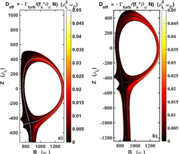
Figure12comparesD^,eff for the short and long leg scenarios
highlighting some common features. Perpendicular transport is enhanced at the outer midplane and it clearly extends poloid-ally upwards towards the top of the main plasma and down-wards close to the X-point, consistently with the ballooning character of turbulent transport [17, 30]. The big difference with respect to the aforementioned ballooned SolEdge2D-EIRENE simulations is represented by a non negligible value ofD^,eff all along the CFR, far from the magnetic separatrix,
causing a non symmetric divertor spreading which translates in a wider lnfor a longer leg. Conversely,D^,effis so small in the
PFR that no big difference in Snis observed. Figures11(b) and
(c) show the evolution of ln and Sn along the poloidal path
from the X-point to the target. On the one hand ln is found to be already different at the divertor entrance (X-point) and to increase gently along the respective leg lengths. On the other Sn
exhibits the same behaviour in both trend and amplitude, suggesting that most of the broadening takes place in thefirst 50 rLbelow the X-point and afterwards it gently increases over the allowed divertor leg length, with a difference of less than 20% at the target. Such an increase of both perpendicular transport scale lengths is related to the presence of a strong steady convective cell around the X-point in TOKAM3X simulations [23]: this causes the mean field transport in this region to be strong, despite the fact that itsfluctuating comp-onent, as was shown infigure10(c), is almost zero.
4. Interpretation
When attempting to reproduce the divertor leg experiment carried out in TCV with simulations, it is observed that in modified magnetic configurations, as the long leg one
presented in this work, a turbulent description is required. Modelling with TOKAM3X shows that turbulent perpend-icular transport, believed to be important and setting lqonly in the main plasma, is instead strong also all along the divertor leg in the far CFR, while almost no transport is predicted in the vicinity of the separatrix and in the PFR. This mechanism is most probably at play also in the more ‘tradi-tional’ divertor configurations (short and medium leg) although less evident because of the short X-point to target distance. For this reason a diffusive picture efficiently describes these equilibria while strongly underestimates lqfor the long leg plasma. For short-legged plasmas though, both a very simplified isothermal model with homogeneous diffu-sion and a more complex fluid code, with radial-dependent perpendicular transport coefficients inferred from exper-imental measurements, match reasonably well with target heat flux profiles.
In the presence of asymmetric divertor transport, when profiles are fit to equation (2), which is based on the hypothesis of symmetric diffusion in the divertor region, a bigger ly is found even though the broadening described here is due to transport occurring below the X-point and, in this framework, should therefore be described by Sy. Therefore, the current
parametrisation has to be generalized for the case of asym-metric divertor perpendicular transport: this could be attempted by introducing a third scale length SCFR describing the
observed, non negligible, transport in the CFR as opposed to <
SPFR SCFRaccounting for the weak transport in the PFR. In
this framework, lq would represent only the main SOL transport and should not be expected to change with Ldiv, while
the broadening of target profiles observed in the experiment, which is a divertor effect, would be captured by SCFR. In any
case a clear role of turbulent, divertor localized, asymmetric perpendicular transport in setting the overall SOL width has to be taken into account for such magnetic geometries.
5. Conclusions
This work constitutes a study of the effect of changing the length of the outer divertor leg on divertor power exhaust in low density, LSN, Ohmic, attached, L-mode plasmas discharges in TCV. Experimental IR and LP measurements of the outer target heatflux profiles show a monotonic increase of lqwith Ldivwith
a factor of 2 difference over the explored range, at constant
BP,omp. LP analysis of target profiles suggests that such
broad-ening is driven by a strong increment inlne whilelTe is only slightly increasing. On the other hand, no trend of Sqwith Ldivis
detected within the resolution of the two diagnostics. Modelling efforts showed that diffusive simulations well reproduce the experimental trends for short-legged plasmas, regardless the assumption of constant or radius-dependent perpendicular transport coefficients. This is the case for both a simple Monte Carlo particle tracer (MONALISA) and a more complex code simulating ions, electrons and neutrals (SolEdge2D-EIRENE). Adding a poloidal dependence (ballooning) of perpendicular transport coefficients to account for localized enhanced transport at the outer midplane, changes the symmetry of target profiles Figure 12.TOKAM3X 2D maps of the effective perpendicular
transport coefficient for (a) the short leg and (b) the long leg simulations.
which exhibit a lowerSq lq ratio, close to what is observed experimentally. Simulations under these assumptions nevertheless yield a constant lq and an increasing Sq.
However, the increase in lne with Ldiv measured in the experiment is in qualitative agreement with the results of a first principle turbulent model (TOKAM3X) highlighting the importance of turbulent transport not only around the outer midplane but also in the vicinity of the X-point and all along the common flux region, causing a stronger broadening of the SOL in the case of a longer divertor leg. These results question the current interpretation of lq as a purely main SOL quantity with BP,ompas the only dependence on control
parameters. In fact, if one assumes a symmetric spreading in the divertor region, in case of long leg configurations as the ones presented here, lqappears to be related to transport in both main SOL and divertor SOL. The implications of this work on future machines like ITER and DEMO are non-trivial and difficult to test on other existing devices because of the limited flexibility of the magnetic geometry. If what ultimately matters for the enhancement of turbulent transport in the divertor is the ratio of the divertor leg length to the total parallel connection length, then a strong effect should not be expected. ITER (and possibly DEMO) will have small Ldiv L, similarly to most existing devices, and
therefore could be satisfactorily described by diffusive codes, consistently with the short-legged TCV equilibria. If, on the other hand, the importance of turbulence in the divertor is inherently related to the length of its leg, then an extra spreading of heatflux profiles could in principle occur in future bigger devices, even in the case of traditional magnetic configurations.
Acknowledgments
This work has been carried out within the framework of the EUROfusion Consortium and has received funding from the Euratom research and training programme 2014–2018 under grant agreement No. 633053. The views and opinions expressed herein do not necessarily reflect those of the Eur-opean Commission. This work was supported by the US Department of Energy under Grant No. DE-SC0010529.
ORCID iDs A Gallo https:/ /orcid.org/0000-0002-9726-1519 C Theiler https://orcid.org/0000-0003-3926-1374 C K Tsui https://orcid.org/0000-0002-7346-8312 References
[1] Loarte A et al 2007 Chapter 4: power and particle control Nucl. Fusion47 S203
[2] Gunn J P, Carpentier-Chouchana S, Dejarnac R, Escourbiac F, Hirai T, Komm M, Kukushkin A, Panayotis S and Pitts R A
2016 Ion orbit modelling of ELM heat loads on ITER divertor vertical targets Nucl. Mater. Energy (https://doi. org/10.1016/j.nme.2016.10.005)
[3] Gunn J P et al 2017 Surface heat loads on the ITER divertor vertical targets Nucl. Fusion57 046025
[4] Pitts R A et al 2017 Physics conclusions in support of {ITER} W divertor monoblock shaping Nucl. Mater. Energy (https://doi.org/10.1016/j.nme.2017.03.005)
[5] Krasheninnikov S I, Kukushkin A S and Pshenov A A 2016 Divertor plasma detachment Phys. Plasmas23 055602 [6] Theiler C et al 2017 Results from recent detachment
experiments in alternative divertor configurations on TCV Nucl. Fusion57 072008
[7] Stangeby P C 2000 The Plasma Boundary of Magnetic Fusion Devices(Bristol: IOP Publishing)
[8] Loarte A et al 1999 Multi-machine scaling of the divertor peak heatflux and width for L-mode and H-mode discharges J. Nucl. Mater.266–269 587–92
[9] Wagner F 1985 A study of the perpendicular particle transport properties in the scrape-off layer of ASDEX Nucl. Fusion
25 525
[10] Eich T, Sieglin B, Scarabosio A, Fundamenski W,
Goldston R J and Herrmann A 2011 Inter-ELM power decay length for JET and ASDEX upgrade: measurement and comparison with heuristic drift-based model Phys. Rev. Lett.
107 215001
[11] Makowski M A et al 2012 Analysis of a multi-machine database on divertor heatfluxes Phys. Plasmas19 056122 [12] Eich T et al 2013 Scaling of the tokamak near the scrape-off layer H-mode power width and implications for ITER Nucl. Fusion53 093031
[13] Scarabosio A, Eich T, Herrmann A and Sieglin B 2013 Outer target heatfluxes and power decay length scaling in L-mode plasmas at JET and AUG J. Nucl. Mater.438 S426–30 Proc. 20th Int. Conf. on Plasma-Surface Interactions in Controlled Fusion Devices
[14] Fedorczak N, Gunn J P, Nace N, Gallo A, Baudoin C, Bufferand H, Ciraolo G, Eich T, Ghendrih P and Tamain P 2017 Width of turbulent SOL in circular plasmas: a theoretical model validated on experiments in tore supra tokamak Nucl. Mater. Energy (https://doi.org/10.1016/j. nme.2017.03.032)
[15] Militello F, Fundamenski W, Naulin V and Nielsen A H 2012 Simulations of edge and scrape off layer turbulence in mega ampere spherical tokamak plasmas Plasma Phys. Control. Fusion54 095011
[16] Horacek J et al 2016 Multi-machine scaling of the main SOL parallel heatflux width in tokamak limiter plasmas Plasma Phys. Control. Fusion58 074005
[17] Gunn J P et al 2007 Evidence for a poloidally localized enhancement of radial transport in the scrape-off layer of the tore supra tokamak J. Nucl. Mater.363–365 484–90 Plasma-Surface Interactions-17
[18] Sieglin B, Eich T, Faitsch M, Herrmann A and Scarabosio A 2016 Investigation of scrape-off layer and divertor heat transport in ASDEX upgrade L-mode Plasma Phys. Control. Fusion58 055015
[19] Maurizio R et al Nucl. Fusion submitted
[20] Gallo A, Fedorczak N, Maurizio R, Theiler C, Elmore S, Labit B, Reimerdes H, Nespoli F, Ghendrih P and Eich T 2016 Effect of plasma geometry on divertor heatflux spreading: Monalisa simulations and experimental results from TCV Nucl. Mater. Energy (https://doi.org/10.1016/j.
nme.2016.10.003)
[21] Bufferand H et al 2015 Numerical modelling for divertor design of the west device with a focus on plasmawall interactions Nucl. Fusion55 053025
[22] Tamain P, Bufferand H, Ciraolo G, Colin C, Galassi D, Ghendrih P, Schwander F and Serre E 2016 The
/orcid.org/0000-0002-7472-7830 H Reimerdes https:/
TOKAM3X code for edge turbulencefluid simulations of tokamak plasmas in versatile magnetic geometries J. Comput. Phys.321 606–23
[23] Galassi D, Tamain P, Bufferand H, Ciraolo G, Ghendrih P, Baudoin C, Colin C, Fedorczak N, Nace N and Serre E 2017 Drive of parallelflows by turbulence and large-scale E×B transverse transport in divertor geometry Nucl. Fusion57
036029
[24] Behn R, Alfier A, Medvedev S Y, Zhuang G, Pasqualotto R, Nielsen P and Martin Y 2007 Edge profiles of electron temperature and density during ELMy H-mode in ohmically heated TCV plasmas Plasma Phys. Control. Fusion49 1289 [25] Boedo J A, Crocker N, Chousal L, Hernandez R, Chalfant J,
Kugel H, Roney P and Wertenbaker J 2009 Fast scanning probe for the NSTX spherical tokamak Rev. Sci. Instrum.80
123506
[26] Pitts R A, Alberti S, Blanchard P, Horacek J, Reimerdes H and Stangeby P C 2003 ELM driven divertor target currents on TCV Nucl. Fusion43 1145
[27] Greenwald M 2002 Density limits in toroidal plasmas Plasma Phys. Control. Fusion44 R27
[28] Canal G P, Lunt T, Reimerdes H, Duval B P, Labit B and Vijvers W A J 2015 Enhanced exb drift effects in the TCV snowflake divertor Nucl. Fusion55 123023
[29] Carralero D, Birkenmeier G, Mller H W, Manz P, deMarne P, Mller S H, Reimold F, Stroth U, Wischmeier M and Wolfrum E 2014 An experimental investigation of the high density transition of the scrape-off layer transport in ASDEX upgrade Nucl. Fusion54 123005
[30] LaBombard B et al 2004 Transport-driven scrape-off-layer flows and the boundary conditions imposed at the magnetic separatrix in a tokamak plasma Nucl. Fusion44 1047