HAL Id: hal-01668634
https://hal.archives-ouvertes.fr/hal-01668634
Submitted on 20 Dec 2017
HAL is a multi-disciplinary open access
archive for the deposit and dissemination of
sci-entific research documents, whether they are
pub-lished or not. The documents may come from
teaching and research institutions in France or
abroad, or from public or private research centers.
L’archive ouverte pluridisciplinaire HAL, est
destinée au dépôt et à la diffusion de documents
scientifiques de niveau recherche, publiés ou non,
émanant des établissements d’enseignement et de
recherche français ou étrangers, des laboratoires
publics ou privés.
Wireless interrogation of small animal phantoms with a
miniature implanted UHF RFID tag
van Hieu Nguyen, Aliou Diallo, Philippe Le Thuc, Robert Staraj, Stéphane
Lanteri, Georges F. Carle
To cite this version:
van Hieu Nguyen, Aliou Diallo, Philippe Le Thuc, Robert Staraj, Stéphane Lanteri, et al.. Wireless
interrogation of small animal phantoms with a miniature implanted UHF RFID tag. 2017 IEEE
Conference on Antenna Measurements & Applications (CAMA), Dec 2017, Tsukuba,Ibaraki, Japan.
pp.1-4, �10.1109/CAMA.2017.8273434�. �hal-01668634�
Wireless interrogation of small animal phantoms
with a miniature implanted UHF RFID tag
V.H. Nguyen
1, A. Diallo
1, P. Le Thuc
1, R. Staraj
11LEAT
Universit Cˆote d’Azur, CNRS 06903 Sophia Antipolis, France
{vhnguyen, aliou.diallo, philippe.lethuc, robert.staraj}@unice.fr
S. Lanteri
2, G.F. Carle
32INRIA: Sophia Antipolis-Mditerran´ee 3IRO-MATOs: Universit Cˆote d’Azur, CEA, BIAM
06107 Nice C´edex 2, France
stephane.lanteri@inria.fr, georges.carle@unice.fr
Abstract—In this article, the RSSI measurement with a minia-ture implanted tag into a small animal phantom, intended to work in the European UHF RFID band is presented. The miniaturization of the radiating element while preserving its efficiency allows the reliable communication between an external interrogation device and the identification tag aimed to be implanted into a small animal. The paper first presents the design of the miniature radiating element. Then, the detailed process to calculate the link budget allowing the estimation of the theoretical power received by the reader is described, showing that the gain of the proposed antenna is adapted to the application. Finally, the measurement of the Received Signal Strength Indication (RSSI) level received by the reader antenna for different positions of a mouse phantom model in a cage is presented. Results show that the proposed antenna can allow the identification of the small animal whatever its position in the cage.
Keywords—implantable antenna; link budget calculation; RFID tag antenna; small antenna; RSSI measurement.
I. INTRODUCTION
Recently, many studies have focused on the design of implantable antennas in the MICS (Medical Implant Commu-nication Service) band (402-405 MHz) dedicated to medical devices implanted in the human or the animal body [1], [2]. However, at these frequencies, the size of the antennas can be a real drawback if we consider small animals. Thus, the use of RFID (Radio Frequency IDentification) technology in UHF band at 868 MHz presents a twofold advantage: it facilitates the tag implantation and it does not require the use of a battery to power the implanted device [3]. However, the main difficulty in designing antennas for bio-implantable communication devices is to provide an efficient structure in spite of the volume constraints and the strong effect of the environmental tissues that surround the implanted antenna and reduce its radiating performance and its efficiency [4] - [6].
In this work, a novel tag antenna has been designed and measured for small animal identification applications. First, the proposed antenna optimized by some new techniques to reach the final design is presented. Secondly, we calculated the theoretical power received by the reader to allow the wave propagation link budget. Finally, the RSSI measurement values of the implantable antenna in the mouse phantom model was investigated for different positions in the cage to evaluate its effectiveness for remote communication.
II. DESIGNOFTHEUHFTAGIMPLANTEDANTENNA
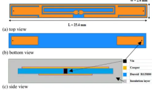
The geometry of the antenna is proposed in Fig. 1. It is composed of a dipole printed on Duroid substrate (permittivity εr= 2.2, dielectric loss tangent tanδ = 0.0009 and thickness
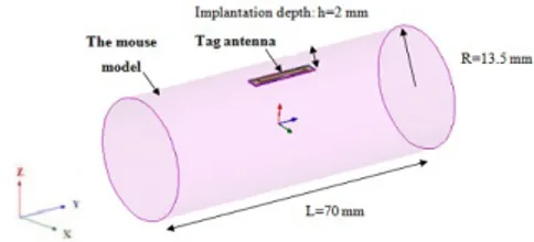
h = 0.127 mm) excited by coupling with a miniature loop antenna which is associated with an Impinj Monza 4 chip [7] presenting an impedance of 5.5-j74 Ohms at 868 MHz. The whole structure (antenna and chip) is protected by a silicone insulating layer which facilitates the electromagnetic transition between the radiating element and the homogenous equivalent model representing the small animal [4]. This model allows the reduction of the computation time during the simulation and the optimization phases. Its total volume (Fig. 2) is π x 13.52 x 70 mm3, with εreq = 40, tanδeq = 0.39 and
σeq = 0.79 (S/m), being respectively the equivalent relative
permittivity, the dielectric loss tangent and the conductivity, taking into account the different layers of the animal body. The total antenna volume is 30.5 mm3, which is very small
compared to other structures operating in the same frequency band [8], [9].
Fig. 1. Geometry of the antenna.
In Fig. 3 (a), we present the reflection coefficient calculated based on equation (1). Its impedance was measured with a Vector Network Analyzer (VNA) Rohde & Schwarz ZVM (10 MHz - 20 GHz). The comparison between simulated and measured reflection coefficients shows that a good matching is always obtained at the working frequency of 868 MHz. Moreover, a total gain value between -17.5 dBi and -30.7 dBi is reached (Fig. 3 (b)). This gain seems acceptable given the dimensions of the antenna and the work previously presented [10], [11].
Fig. 2. Implanted tag in the homogenous body phantom.
S11=
Zant− Zchip∗
Zant+ Zchip
(1)
Fig. 3. (a) reflection coefficient and (b) simulated radiation pattern of the implanted antenna.
III. LINKBUDGETCACULATION
The objective of this section is to calculate the theoretical received power Prx reader by the reader when the antenna is
implanted in the phantom model of a small animal. The reader antenna is placed in a confined space with reduced dimensions and has a limited gain around 3.2 dBi. The power emitted by the reader is 27 dBm and respects the ERC recommendations as the ISM band at 868 MHz imposes a maximum power of 500 mW (27 dBm) [12]. The power backscattered by the implanted tag and received by the RFID reader must be greater than its sensitivity (the minimum power required to detect the feedback signal of the tag) to guarantee the communication of the system. Thus, based on the reader’s performance, the attenuation parameters Am in the animal
environment, the losses at the interface Lint between the air
and the animal environment, and considering that the model phantom is placed in the center of the reader antenna, we can express the received power by the reader by the following equation [13] - [15].
Prx reader =
Ptx readerG2tagG2reader
P LintP Am
(2) Let us assume that di (i = 0, 1) is the length of the
propagation channel of the wave in each medium (Fig. 4). In this case, d0 is the thickness of the air layer and d1 is
the equivalent thickness of the body layer of the animal. The attenuation of the medium Am is defined by the following
equation:
Am= (
λi
4πdi
)2e−αidi (3)
Where α0= 0 is the attenuation constant in the air and α1
is the equivalent attenuation in the animal body:
α1= ω s µreqεreq 2 [ r 1 + ( σeq ωεreq )2− 1] (4)
Moreover, we consider that the incident wave propagates through the different media as shown in Fig. 4 with different impedances that produce different losses Lintat the interfaces,
defined by the equations in [16]. The reflection coefficient Γ1
can be expressed directly in terms of ρi and d1.
Fig. 4. Transmission and reflection on the dielectric layer.
ρ0= η1− η0 η1+ η0 (5) ρ1= η0− η1 η0+ η1 (6) Γ1= ρ0+ ρ1e−j2k1d1 1 + ρ0ρ1e−j2k1d1 (7) Lint= |Γ1|2 (8)
Where ρi denote the elementary reflection coefficient to the
left of the two interfaces, ki= 2π/λi is the wave number, λi
is the wavelength in each medium and ηi is the characteristic
impedance of each environment: η0and η1are the impedances
of the air layer and of the animal body, respectively, and they are defined by:
η0= r µ0 ε0 (9) η1= rµ reqµ0 εreqε0 (10)
The characteristics of the reader and its antenna are given in Table 1: TABLE I READERPARAMETERS Reader Sensitivity
Reader Trans. Power Ptx reader
Reader Antenna Gain (Greader)
-82 dBm 27 dBm 3.2 dBi
The reader antenna inspired from [17], is presented in Fig. 5. It is made up of an annular ring slot, excited by a micro-strip line on the lower face of the substrate. The micro-strip/slot line transition is used in combination with a small open circle stub for the matching. A U-shaped slot stub is also used to miniaturize the whole diameter of the antenna and to obtain the circular polarization used in UHF RFID standard. The simulated and measured S11 coefficients for this antenna are
given in Fig. 6. A good agreement is obtained and the antenna is well matched in the UHF band with a value of S11 around
-13 dB at 868 MHz. Thus, with this radiating element, we obtain a received power Prx reader between -34.5 dBm and
-60.9 dBm for an emitted power of 27 dBm according to equation (1) when the model phantom is placed in the center of the antenna reader.
Fig. 5. Antenna reader with its system of coordinates and the phantom with its tag inside.
Fig. 6. Simulated and measured S11parameter for the reader antenna.
IV. RSSIMEASUREMENTS
Based on the previous section III, the RSSI theory value is expressed by the following equations:
Prx tag= Ptx readerGreader P LintP Am (11) RSSI(dBm)= Ptx tag (dBm)− X Loss = Prx reader (12)
For the measurements, a phantom body was realized by combining diethylene glycol butyl ether (44%) and de-ionized water (56%) [18], contained in a 60 ml polypropylene cylin-drical flask having the dimensions and, more or less, the shape of the animal body (Fig. 7 (a)).
Fig. 7. (a) antenna prototype in the phantom model, (b) measurement set-up.
The implantable tag prototype (Fig. 7 (a)) has been tested with a RFID reader antenna connected to an Impinj Speedway Revolution R420 reader [19] able to interpret the data received from the implanted antenna as shown in Fig. 7 (b). The cage bottom surface has been divided into a coordinate model to control exactly the phantom model position (Fig. 5 and Fig. 8).
Fig. 8. Three row positions of the phantom model oriented along the X axis (a) and along the Y axis (b), varying according to the Y axis.
The software interface is implanted into a computer con-nected to the reader and allows us to control the whole system (Fig. 7). With these elements, the reader is able to detect the tag in the Plexiglas rack cage after a few seconds. Fig. 9 presents the measured values obtained for the two orientations of the phantom. As we can observe, the RSSI value is close to the maximum when the phantom model is above the center of the reader antenna. The small shift in the position compared to the center of the antenna is due to the asymmetry of the plastic casing of the phantom, the asymmetry of the antenna of the reader and uncertainties in the positioning. The influence of this asymmetry is logically more important for an orientation of the phantom along the Y axis than along the X axis.
The measured average value of the RSSI varies between -48 dBm and -68 dBm, which is close to the theoretical values calculated previously. These results also prove the potential of the whole system to detect, identify and localize small animals equipped with such miniaturized implanted tags.
Fig. 9. RSSI measured values at 868 MHz when the phantom model is oriented along the X axis (a), Y axis (b) and moves along the Y axis.
V. CONCLUSION
In this paper, the antenna design of an implanted RFID tag dedicated to very small animals and intended to operate in the UHF RFID band is presented. The studies of the link budget and the RSSI measurement between the implanted antenna and the interrogating system in the specific environment of the project also show that the performance of the designed antenna allows its use in the intended application.
ACKNOWLEDGMENT
This work was partly funded by the French Government (National Research Agency, ANR) through the Investments for the Future Program reference #ANR-11-LABX-0031-01.
REFERENCES
[1] C. M. Furse and A. Chrysler, ”A History & Future of Implantable Antennas,” in IEEE Antennas and Propagation Society International Symposium (APSURSI), pp. 527-528, 2014.
[2] A. Kiourti, K. A. Psathas, and K. S. Nikita, ”Implantable and ingestible medical devices with wireless telemetry functionalities: A review of current status and challenges,” in Bioelectromagn. Wiley Period. Inc., vol. 35, no. 1, pp. 1-15, 2014.
[3] L. Catarinucci, R. Colella, L. Mainetti, V. Mighali, L. Patrono, I. Sergi, and L. Tarricone, ”Near Field UHF RFID Antenna System Enabling the Tracking of Small Laboratory Animals,” in Int. J. Antennas Propag., vol. 2013, pp. 1-10, 2013.
[4] F. Merli, B. Fuchs, J. R. Mosig, and A. K. Skrivervik, ”The effect of insulating layers on the performance of implanted antennas,” in IEEE Trans. Antennas Propag., vol. 59, no. 1, pp. 21-31, 2011.
[5] A. Karlsson, ”Physical limitations of antennas in a lossy medium,” in IEEE Trans. Antennas Propag., vol. 52, no. 8, pp. 2027-2033, 2004. [6] A. C. Gurveer Kaur Chauhan, Gurpreet Kaur, ”Implantable antennas for
biomedical applications,” in Comput. Intell. Commun. Networks (CICN), 2015 Int. Conf., vol. 11, no. 9, pp. 5632-5636, 2016.
[7] Monza 4 RFID Impinj chip datasheet [Online]. Available: https://support.impinj.com/hc/en-us/articles/202756908-Monza-4-RFID-Tag-Chip-Datasheet
[8] A. Garcia-Miquel, B. Medina-Rodrguez, N. Vidal, F. M. Ramos, E. Roca, and J. M. Lopez-Villegas, ”Design and characterization of a miniaturized implantable UHF RFID tag based on LTCC technology,” in 11th European Conference on Antennas and Propagation (EUCAP), pp. 1024-1026, 2017.
[9] Zhao, R. L. Rennaker, C. Hutchens, and T. S. Ibrahim, ”Implanted miniaturized antenna for brain computer interface applications: analysis and design,” in PloS One, vol. 9, no. 7, p. 1-10, 2014.
[10] A. Kiourti and K. S. Nikita, ”A review of implantable patch antennas for biomedical telemetry: Challenges and solutions,” in IEEE Antennas Propag. Mag., vol. 54, no. 3, pp. 210-228, 2012.
[11] C. Liu, Y.-X. Guo, and S. Xiao, ”A review of implantable antennas for wireless biomedical devices,” in Forum for Electromagnetic Research Methods and Application Technologies (FERMAT), 2016.
[12] ERC Recommendation (70-03) [Online]. Available: http://www.erodocdb.dk/docs/doc98/official/pdf/rec7003e.pdf
[13] D. M. Dobkin, ”The RF in RFID”, in Second Edition: UHF RFID in Practice”, 2 edition. Amsterdam: Newnes, 2012.
[14] Y.-P. Luh and Y.-C. Liu, ”Emerging Communications for Wireless Sensor Networks,” in Mod. Mech. Eng., vol. 03, no. 03, pp. 115-120, 2013.
[15] S. Korea, C. Pu, C. Pu, and H. Lee, ”Emerging Communications for Wireless Sensor Networks,” Chapter 11 ”Indoor Location Tracking using Received Signal Strength Indicator,” In Tech Europe, Feb.2011. [16] S. J. Orfanidis, ”Electromagnetic Waves and Antennas,” in
Prentice-Hall, 2003.
[17] C. Phatra and P. Krachodnok, ”A circularly polarized antenna for UHF RFID reader,” in 11th International Conference on Electrical Engineering/Electronics, Computer, Telecommunications and Information Technology (ECTI-CON), pp. 1-4, 2014.
[18] P. Perrissol, A. Diallo, P. Le Thuc, R. Staraj, and G. F. Carle, ”Perfor-mance of a cross dipole antenna dedicated to biological telemetry,” in The 8th European Conference on Antennas and Propagation (EuCAP 2014), pp. 2174-2177, 2014.
[19] RFID Impinj Speedway Revolution R420 reader [Online]. Avail-able: https://support.impinj.com/hc/en-us/articles/202755358-Speedway-Revolution-Installation-Operations-Guide