HAL Id: hal-01363622
https://hal.archives-ouvertes.fr/hal-01363622
Submitted on 20 Dec 2016HAL is a multi-disciplinary open access archive for the deposit and dissemination of sci-entific research documents, whether they are pub-lished or not. The documents may come from teaching and research institutions in France or abroad, or from public or private research centers.
L’archive ouverte pluridisciplinaire HAL, est destinée au dépôt et à la diffusion de documents scientifiques de niveau recherche, publiés ou non, émanant des établissements d’enseignement et de recherche français ou étrangers, des laboratoires publics ou privés.
Stabilization of a stimulated Brillouin fiber ring laser by
strong pump modulation
Jean Botineau, Claude Leycuras, Carlos Montes, Eric Picholle
To cite this version:
Jean Botineau, Claude Leycuras, Carlos Montes, Eric Picholle. Stabilization of a stimulated Brillouin fiber ring laser by strong pump modulation. Journal of the Optical Society of America B, Optical Society of America, 1989, 6 (3), pp.300. �10.1364/JOSAB.6.000300�. �hal-01363622�
300 J. Opt. Soc. Am. B/Vol. 6, No. 3/March 1989
Stabilization of a stimulated Brillouin fiber ring laser by
strong pump modulation
Jean Botineau, Claude Leycuras, Carlos Montes, and Eric Picholle
Laboratoire de Physique de la Matiere Condens6e, Universit6 de Nice, Parc Valrose, 06034 Nice Cedex, France
Received March 1, 1988; accepted November 17, 1988
A stable train of compressed Stokes pulses (to -10 nsec) is obtained in a stimulated Brillouin fiber ring laser (of length L = 83 m) by periodically interrupting the argon-ion cw pump beam with an intraring cavity acousto-optic
modulator. Interruption of the pump action, at each round-trip time t Ln/c, permits damping of the excited sound waves that accumulate at the entry of the fiber owing to the inertial response of the material, well described by the coherent three-wave stimulated Brillouin scattering model (C3W-SBS equations). Amplification and compres-sion of the backscattered Stokes pulse are limited by nonlinear optical Kerr effect, which is incorporated into the C3W-SBS equations.
1. INTRODUCTION
Stimulated Brillouin backscattering (SBS) is a dominant nonlinear effect in single-mode optical fibers, where it ap-pears at moderate threshold values.",2 In particular, SBS is
used as a gain process in fiber lasers,3-8in which a
narrow-linewidth laser pump source, yielding high-power flux densi-ties into the fiber, amplifies the stimulated backscattered Stokes background on a long interaction length. Genera-tion of periodic trains of short Brillouin Stokes pulses has been attributed to mode locking,5 9"10i.e., to phase synchro-nization of longitudinal modes in the first Stokes component that cover the Brillouin gain bandwidth. Mode locking may be installed by the relaxation behavior that occurs in the oscillators as a result of periodic pump depletion or active modulation. However, the temporal behavior of the SBS process describing these finite-cell-length oscillations" or relaxation oscillations'2 has been investigated within the strongly damped approximation (called here the SDA
mod-el) for the sound wave, which is relevant only for the station-ary case'3 or for weak Stokes pulses, as we shall discuss
below. For long interaction times and high amplification and compression of the Stokes, pulse a description starting from the well-established coherent three-wave SBS equa-tions derived for electrostrictive continuous media,4
"15 called here C3W-SBS equations, is necessary (note that the resonant condition in this model implies second-order non-linearities); the asymptotic behavior of an initial bounded Stokes pulse whose amplitude grows and whose width shrinks at the expense of a continuous pump wave has been
studied in Refs. 16 and 17.
Our aim in this paper is to compare experimental results obtained in fiber ring configurations with those provided by numerical simulation of the appropriate C3W-SBS equa-tions through the slowly varying amplitude approximation,
which is valid here for the optical waves as well as for the
sound wave. Modeling was done simultaneously with an
experiment on a single-mode silica-fiber ring laser, of length L = 83 m, pumped by a single-mode argon-ion cw laser. The
properties determined from the numerical simulation have permitted improvement of the experimental configuration.
For example, numerical calculations show that, when the backscattered Stokes pulse leaves the nonlinear medium and cw pump input is maintained, the amplitude of the sound wave can remain high, especially at the fiber end used for the pump coupling. This accumulation of the excited phonons owing to the inertial response of the sound waves,
well described by the C3W-SBS equations, is responsible for
shortening the effective length of the nonlinear medium by depleting the pump just at its entry and for spreading the Stokes-pulse tail. Thus one of the aims of an improved experimental setup is to permit spontaneous phonon damp-ing by interruptdamp-ing the pump input coupldamp-ing into the fiber at a frequency equal to the round-trip photon frequency (v, =
1/t, c/Ln) with an acousto-optic modulator (AOM) in order to stabilize the amplified and compressed train of Brillouin Stokes pulses. This device also prevents reflec-tions of the Stokes pulses on the output laser pump mirror by isolating the laser pump from the backscattered Stokes pulses. We improve our description of the finite spatial width of the Stokes pulses observed in the actual experiment by including optical Kerr nonlinearity in the C3W-SBS equations, which introduces phase modulation,'8 and here
amplitude modulation too, and limits the compression. C3W-SBS equations have already been used to interpret pulse compression (from 20 to 2 nsec) by backward SBS in a tapered optical waveguide filled with methane at 130 atm.19 However, in nonlinear-optical problems dealing with SBS (and also with stimulated Raman scattering), the SDA mod-el is commonly used for the dynamical equations."1-3 This
model may be derived from C3W-SBS equations by assum-ing that the sound response is instantaneous and the pho-nons are motionless. Such a description reduces the system to the evolution of two counterpropagating optical waves coupled together by third-order susceptibility: it amounts to considering two equations involving optical intensities, disregarding phases. The SDA model is exactly solvable20
but obviously cannot describe the interaction outside the spatial overlapping domain of the two electromagnetic wave
envelopes.
In Section 2 we recall the coherent SBS interaction brief-ly, and we present the basic equations that are used for the
0740-3224/89/030300-13$02.00 © 1989 Optical Society of America
Vol. 6, No. 3/March 1989/J. Opt. Soc. Am. B 301
numerical simulations. In Section 3 we describe the
experi-mental setups and give the experiexperi-mental results for the two ring configurations used as fiber oscillators. The first
sim-ple setup, without an AOM, yields a nonstable regime, and we observe that when pump intensity is increased well above SBS threshold several Stokes pulses are simultaneously ex-cited along the fiber, among which are stationarily amplified
only those that are separated by submultiples of the
round-trip period. To explain this fact we present a simple
argu-ment based on stationarity, total pump depletion by each
leading Stokes pulse, and exponential SBS Stokes gain.
The second setup, in which the AOM is tuned to the round-trip photon frequency v,, couples the laser input to the fiber ring oscillator through first-order Bragg diffraction, while feedback is achieved through zero-order Bragg diffraction. This setup yields a stable train of amplified and compressed Brillouin Stokes pulses. In Section 4 we give the numerical results: the time behavior of the field amplitudes governed by C3W-SBS plus the optical Kerr equations agrees well with the experimental results. Finally, a conclusion is
drawn in Section 5 in which the possibility of quasi-solitons in the C3W-SBS dynamics is envisaged.
2. MODELS OF STIMULATED BRILLOUIN
SCATTERING
A. Coherent Three-Wave SBS Model
In SBS a forward-propagating pump wave (at frequency wl
= kic) couples with the thermal phonon fluctuations of the
medium and stimulates a counterpropagating Stokes beam (at frequency (*2 = wl - w,), downshifted by the phonon
frequency ws = 2c~wln/c, where n is the refractive index, c, the sound velocity, and c the velocity of light in vacuum.
The resonance condition for three-wave coherent interac-tion provides maximum power transfer when the
wave-vec-tor mismatch is zero: k = k - k2. In a single-mode fiber it
is possible to reduce the wave description to three planar
homogeneous propagating waves by following a treatment similar to that of Ref. 21: (1) a forward-propagating pump
wave Ei(x, t) = El(x, t)exp[i(klx - wt)] exhibiting depletion
during the amplification and compression of (2) a backscat-tered Stokes wave E2(x, t) = E2(x, t)exp[-i(k2x + W2t)] and
(3) a forward-damped sound wave p5(x, t) = ps(X, t)exp[i(k~x
- wxt)] induced by electrostriction. Counterpropagation then yields the phase-matching condition: k = k, + k2
2kl.
To describe the coherent time-dependent behavior of SBS in single-mode fibers, we can use the well-established C3W-SBS equations derived for electrostrictive continuous me-dia,'4"15which concern the three coupled waves, E1, E2, and
p,, having amplitudes El, E2, and ps, respectively, and some
damping yi. In one-dimensional optical media of dielectric permeability E, and for parallel polarized electromagnetic
waves, we can write
[at2+ 2,ylat - (c/n)2
O.2]El = -(1/n2)t 2[(OE/0pEWE2I, (1)
[8t2 + 2 y2at - (c/n)2 x2]E2 = (1/n2)Ot2 1(d/p~h8*E1I, (2)
(a2+ 2-yst - 82Ox2)h = (poeo/2)(aE/p)aX2(ElE2*). (3) It is usual to introduce the slowly varying envelope approxi-mation for the waves; the complex amplitudes E1, E2, and p,
are assumed slowly varying in time and space so that the development of the second derivatives of the complete fields
(E1, E2, and pi) yields
at2 -2iajdt + at2- _ -2iwjat - j2,
8X2 _± 2ikjax + x2 -kj 2 +2ikjx -kj2
where the right-hand operators apply only to the ampli-tudes. This is a good approximation for the electromagnetic waves since their frequencies wj are high compared with the time variation at of the amplitude. For the sound waves two
cases are possible: (1) In the strong-coupling case (4'> bc =
6 X 10¹² W/cm2 in silica) the sound response time W-1 may
be greater than the inertial response time r = (tpj/p)-l, and the dynamics associated with the second derivative must be
included, which leads to a complex phase-amplitude
evolu-tionl7 (this case is relevant for laser-plasma interaction problems). (2) However, in typical optical-fiber
experi-ments we are addressing the small-coupling case ( << ic),
and the slowly varying envelope approximation for the sound-wave amplitude evolution holds, too.'6 The electro-strictive field Es associated to the phonon amplitude p is
given by ps = io-E5, where = (pon3e0/2cc)l/2 and E0 is the
vacuum dielectric constant. We write Eqs. (1)-(3) in di-mensionless form after introducing time ( = 1/KEn) and
length (A = cT/n) scales, where Ep is the input amplitude of
the pump El and
K
=
I
/2 ' 12
(4)
is the SBS coupling constant for optical materials2; for an
optical fiber of fused silica with a refractive index n = 1.46,
an elasto-optic coefficient P12 = 0.286, a sound velocity c5 = 5.96 X 10³ m sec'1, and an unperturbed fiber density p0 = 2.21 X 10³ kg m-3, we obtain for the pump wavelength X = 5145
A
the SBS coupling value K = 65.9 m sec-1 V-1. If wechange (Ei/Ep - Ej; t/r = tKEp - t; x/A = xnKEp/c - x),
introduce (,u = -yr = 'Ys/KEp; se = Yl,2T = 7Y1,2/KEp), and neglect the sound-wave velocity in Eq. (3) (because nc,/c
10-5 in silica), Eqs. (1)-(3) yield the dimensionless form
(5)
(at + ax + Ae),i =-E2Ess
(at -
Ox
+ Ae)E2=EE,*,
(a, + AL)E, = E1E2*.(6)
(7)
Starting from an initial bounded Stokes background E2, the
transient and asymptotic evolution governed by Eqs. (5)-(7) in the presence of a constant input pump wave El without optical attenuation (Ae = 0) has been considered in Ref. 16.
During the first stage, the Stokes-pulse growth is exponen-tial until its amplitude becomes comparable with the pump
amplitude. A second regime follows in which total and
abrupt depletion of the pump field El is accompanied by a sharp leading edge of the backscattered Stokes envelope E2,
which is amplified and compressed. The backscattered
wave envelope exhibits a set of large peaks of decreasing
amplitude, the amplitude of the first growing linearly with time t while its width shrinks as lit. Later there is a spatial spreading of the Stokes tail because of the finite response time of the sound waves (inertial response time). The
302 J. Opt. Soc. Am. B/Vol. 6, No. 3/March 1989
phases of the complex amplitudes E, are time and space independent, except for the sudden r shifts that appear
when the fields vanish (r pulse envelope2 2). B. SBS Adiabatic Model: SDA Model
In order to compare the C3W-SBS model governed by Eqs. (5)-(7) with the commonly used adiabatic modelll1 213 20
in which the inertial response of the sound wave is neglected
(MAES >> atE8), let us write the evolution equations for the flux
intensities 4'L = (nEoc/2)JEi2 by setting Es = EjE2*/1 in Eq.
(7) in dimensioned units:
[8x + (n/c)(Ot + "Ye)]4'i = -g4'' 2, (8)
[a. - (n/c)(at + 'Ye)]42 = -gbl' 2, (9) where the Brillouin gain coefficient g is given by
4 27rn'pl22
1
g= 4 K2 = = 4.62 X 1"mW'
,CO2 CX\2poc.lŽAvB
where APB = 150 MHz is the Brillouin linewidth (FWHM) in
pure fused silica.23'24
If we consider the amplification regime already described for an initial spatial bounded Stokes envelope E2 in the
presence of a constant pump El, the SDA model (which is exactly solvable20) properly describes the first interaction stage where E2exhibits exponential amplification and
steep-ening (compression) during its backward motion at the ex-pense of El, which is depleted.16 When E2is greater than El
and the width of the E2 peak becomes extremely small, the characteristic evolution time becomes smaller than the damping time s'l of the sound wave (tpts >> sps, i.e., atE >>
,MEs), the SDA adiabatic model fails. Neither the linear amplification with time of the leading E2peak, obtained with the C3W-SBS equations, nor the spreading of its tail is described through the SDA model; indeed, that model can-not account for the interaction between the sound wave and the pump wave after (or outside) the Stokes-pump interac-tion, because within this approximation the sound wave vanishes in the absence of El or E2. In particular, the SDA model will be inappropriate to describe
pump-wave-Stokes-pulse interactions in a ring configuration (such that consid-ered here), in which the active medium retains a memory of former interactions, because of the finite response time of
sound waves.
C. SBS Coupled to the Nonlinear-Optical Kerr Effect
When the SBS amplification and compression of the back-scattered Stokes pulse becomes important we must look for saturation mechanisms in order to interpret the finite spa-tial width observed in the actual experiment. For a time width of the order of y-l, i.e., for few nanoseconds, the dispersion does not act efficiently. However, self-phase modulation due to the nonlinear-optical Kerr effect8seems
to be a good candidate because it couples phases and ampli-tudes, producing self-amplitude modulation and spreading the Stokes pulse, like the time behavior obtained for a simi-lar problem in which dispersion instead of the SBS effect is taken into account.25 26 The refractive index of the fiber
medium is
n = no + n2E2/2, (10)
where no (=1.46) is the unperturbed refractive index, n2
(=1.27 X 10⁻²² m2V-2for silical8) is the Kerr coefficient, and = E + E2is the total electromagnetic field. Here, we retain only the zero-frequency terms of the nonlinear Kerr
effect, which describe a uniform bias of the nonlinear index. The other terms, called holographic terms,27are oscillating
terms at frequencies different from those involved in SBS, namely, at exp[3i(kx + t)], exp[i(3kx + wt)], and exp[i(kx + 3wt)]. They can in themselves be responsible for Raman instabilities2 7 but with lower gains than the SBS process considered here. Nevertheless, the bias terms of the refrac-tive index are resonant with SBS and will be responsible for self-phase and self-amplitude modulation, which considera-bly modify the amplitude profile and width of the backscat-tered amplified Stokes pulse. Introducing the nonlinear optical Kerr effect into the dimensionless C3W-SBS Eqs. (5)-(7), we obtain the dimensionless C3W-SBS-K equations
(at + a. + Me)E 1= -E2E8 + Kr(IEI
2+ 2IE
2I2)El,
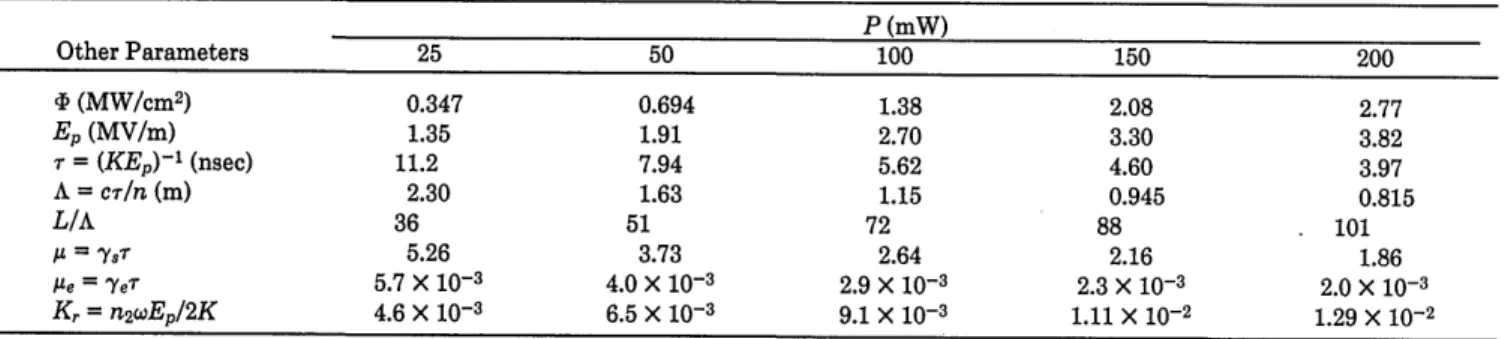
Table 1. Computation Parameters for the Fiber Used in the Experimentsa
P (mW) Other Parameters 25 50 100 150 200 '1 (MW/cm2) 0.347 0.694 1.38 2.08 2.77 E, (MV/m) 1.35 1.91 2.70 3.30 3.82 r = (KEn)-l (nsec) 11.2 7.94 5.62 4.60 3.97 A = cr/n (m) 2.30 1.63 1.15 0.945 0.815 L/A 36 51 72 88 101 I = '/y5 5.26 3.73 2.64 2.16 1.86 Ie = YeT 5.7 X 10⁻³ 4.0 X 10⁻³ 2.9 X 10⁻³ 2.3 X 10⁻³ 2.0 X 10⁻³ Kr = n2wEp/2K 4.6 X 10⁻³ 6.5 X 10⁻³ 9.1 X 10⁻³ 1.11 X 10⁻² 1.29 X 10⁻²
a Length L = 83 m, effective cross section S = 7.2 X 10⁻¹² M2. Other notation: P is the pump power coupled into the fiber
'1 is the pump flux intensity
E, is the electromagnetic field corresponding to '
r is the SBS characteristic time [where the coupling constant given by Eq. (4) is K = 65.9 m sec-1V-l] A is the SBS characteristic length
A is the dimensionless sound-damping rate (corresponding to y = 7rAvB = 470 MHz)
pe is the dimensionless optical attenuation (corresponding to 21.7 dB km'1) K, is the dimensionless Kerr/SBS rate coefficient (where n2= 1.27 X 10⁻²² m
2 V-2)
w is the laser frequency (=3.66 X 10¹⁵ sec-').
(11) Botineau et al.
Vol. 6, No. 3/March 1989/J. Opt. Soc. Am. B 303
(at - a. + Ae)E2 = EE8* + iKr(21EiI2 + E2 )E2, (12)
(at + )E, = EE2*' (7)
where the dimensionless coefficient comparing the
nonlin-ear-optical Kerr effect with the SBS effect is given by
Kr = n2wEp/2K, (13)
K (m secl V-1) being the SBS coupling coefficient given by Eq. (4).
The validity domain of Eqs. (11) and (12) is restricted to the perturbative Kerr contribution. For the pump
intensi-ties used here, we have Kr << 1 (see Table 1), which gives an
upper limit for the amplified E2field (E2< 13 in the Ep units
used here) within this description. Redimensionalization of
Eqs. (11) and (12), by including Kr in new field, time, and
space variables, permits suppression of Kr from these equa-tions with the validity condition reduced to new field ampli-tudes smaller than unity.
Within the pure C3W-SBS description given by Eqs. (5)-(7), the simple phase dynamics already discussed reduces the problem to a study of three partial differential equations for the real part of E.16 With the SBS-K Eqs. (11), (12), and (7) the phase dynamics plays a nontrivial role: the nonlin-ear coupled phase-amplitude evolution leads to amplitude modulation and subsequently spreads the width of the
am-plified E2pulse.
3. EXPERIMENTAL PROCEDURE AND RESULTS
The purpose of the experiment described here is to design a proper setup for SBS analysis in a planar-wave configura-tion. The active medium is an 83-m-long single-mode recti-linearly birefringent fiber F, with a. 3-,Mm-diameter pure-silica core surrounded by a boropure-silicate optical cladding, used along one of its neutral axes, such that the interacting optical waves are parallel polarized. In order to have a large
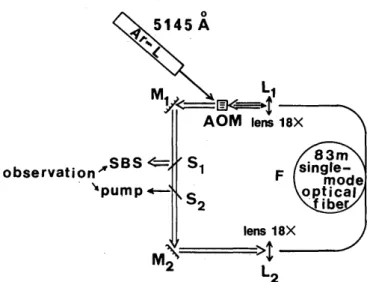
interaction length, we pump the fiber with a cw single-mode ionized argon-ion laser emitting at X = 5145 A. To work with low pumping power levels, we mount the fiber in an optical ring oscillator in which the feedback is achieved by
the two mirrors, Ml and M2; input and output fiber
cou-plings are obtained through 18X microscope lenses (see Figs. 1 and 2). Detection is achieved with a 500-psec rise-time silicon diode connected to a 400-MHz oscilloscope. This
mounting set then acts as an optically pumped Brillouin
fiber laser.3-9 We define the forward direction in the ring
oscillator as the pump-beam direction.
Thermal phonon fluctuations in the fiber are then
ampli-fied by the cw pump beam to give rise to backward-scattered
Brillouin Stokes pulses, which are recoupled into the fiber after a round trip in the oscillator for further amplification.
The pump wave's coupling efficiency is 60%, and the fiber's
linear attenuation is 34%. We estimate the input coupling efficiency of the Brillouin pulses to be 80% and the output
fiber coupling efficiency to be 90%, taking lens losses into
account.
A ring oscillator configuration3'4'9 rather than a
back-and-forth oscillator5'6'28was chosen in order to optimize the
inter-action length. We have successively used the two ring oscil-lators shown in Figs. 1 and 2 to solve different experimental
problems described below.
Li IAr-L
-
_A1 515 Ml tens 1 8XI M2 lens 18Xpump
Em
observation
"'
SBSFig. 1. Basic mounting set of the first fiber oscillator: constant pump input.
observation
SBS
'pump
stimulated Brillouin ring
AOM lens 18' '_ 1 1~S F F(
S
2 lens 18X 2 , L2Fig. 2. Mounting set for the second stimulated Brillouin ring fiber oscillator: modulated pump input.
A. First Ring Oscillator
We start with the simplest configuration, the experimental setup of which is depicted in Fig. 1. The two mirrors Ml and
M2 are 50% beam splitters. Pump coupling is achieved
through Ml, and either the output pump beam or the
Bril-louin pulses may be observed through M2.
Experimental Results
The backward output signal is recorded with a fast detector,
while the laser pump power level is progressively increased to 600 mW. At low pump level, backward scattering
origi-nates mainly in cw Rayleigh scattering in the fiber and from reflections upon the different optical surfaces. When the pump power reaches a characteristic threshold value (here
less than 50 mW at the output of the pump argon laser), a
temporal structure arises in the backward beam, consisting of a periodic train of stimulated Brillouin pulses, the tempo-ral repetition rate of which corresponds to a pulse round-trip time in the ring tr 1/yr (=415 nsec within this configura-tion, taking into account the 11-nsec transit time outside the fiber). The temporal width of the Brillouin pulses is typi-cally in the 20-30-nsec range, with a sharp peak, the maxi-mum of which is difficult to determine but may be estimated as being several times the pump power coupled into the fiber
304 J. Opt. Soc. Am. B/Vol. 6, No. 3/March 1989
20-30 nsec
t
a
0 nsec
t
b
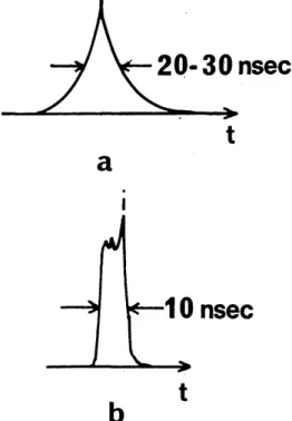
Fig. 3. Typical stimulated Brillouin pulses obtained at the output
of the oscillator of Fig. 1.
(Fig. 3a). In fact, this amplitude is highly unstable and fluctuates between zero and a maximum value; sometimes some sharper and narrower pulses appear, probably with an internal fine structure not resolved by our detector (Fig. 3b).
We also measure the average output pump power level, which exhibits a saturation value close to 30 mW directly
after the fiber and half of this value at the oscillator output. On the other hand, the average backward-scattered power is almost linear with the input power.
Another interesting feature is the pulse-repetition-rate evolution with the pump power level. As we pointed out in Section 1 and has been noted by several authors,28'29 when stimulation occurs the frequency repetition rate of the Bril-louin pulses, corresponding to a pulse round-trip time tr (=415 + 5 nsec) at the low pump level, doubles at the higher
pump level (210 nsec between two pulses). When the pump
power level is increased still more, we observe that the repe-tition rate is multiplied by three and then by four and even five, with an increasing instability among all these regimes. At such a pump power level (some hundreds of milliwatts at the output of the argon laser) high transient regimes of randomly distributed Brillouin pulses appear. When the repetition rate increases by an integer factor (2, 3, ... ), the
pulse width shown in Fig. 3a seems to decrease in the same
ratio.
We also have successively probed the backward- and
for-ward-output frequency power spectra, using the experimen-tal setup of Figs. 4 and 5. These experimenexperimen-tal mountings use a 165-mm Jobin & Yvon holographic diffraction grating engraved with 1872 lines/mm and a 50-cm focal-length and
f/9 aperture objective well corrected for aberrations
(Clair-aut objective). This setup gives a theoretical spectral
reso-lution of less than 2 GHz, which ensures a good separation for the Brillouin lines (v = 34 GHz) but does not give any
information on the fine structure of each individual line Gv2
< AVB = 150 MHz, where &'2 corresponds to the shortest
measured time width At2 = 10 nsec of the backscattered
Stokes E2pulse).
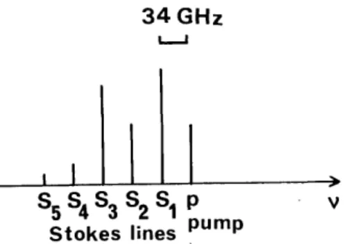
The spectra are depicted in Figs. 6 and 7. The backward spectrum, obtained by using the experimental setup of Fig.
4, exhibits as many as five Stokes lines (Fig. 6), and the
forward spectrum (Fig. 7, corresponding to the experimental setup of Fig. 5) as many as five Stokes lines and four anti-Stokes lines. The frequency shift between two adjacent lines corresponds to the Brillouin spectral shift ( = 34 GHz), and the number of spectral lines increases with the
coupled pump power level.
The experiment could be improved by analyzing the Bril-louin spectrum with a spectrum analyzer, which would per-mit better resolution of the fine structure of the Brillouin line and better interpretation of the process that leads to pulse generation.
Discussion
Starting from some experimental observations, a simple ex-planation for the frequency-multiplication rate may be giv-en, although details of exactly what happens in the oscillator
need not be known. We have to assume only (1) oscillator
quasi-stationarity, which corresponds to the experimental observation in a time range of the order of 100 Atsec, (2)
exponential gain (which is valid for the low pump levels used
here), and (3) strong enough pump depletion to reduce the pump level below the Brillouin stimulation threshold after the interaction with a backscattered Brillouin pulse (which
Clairaut objective ... . diffraction grating i screen lens 18X F
Fig. 4. Mounting set for the observation of the
spectrum corresponding to the setup of Fig. 1. backward power
\
screen
L4/g
lens 18X
Clairaut .. 0to fiber
objective input end
lens 18X
M2 iber
~f
diffraction F
grating L2
Fig. 5. Mounting set for the observation of the forward power
spectrum corresponding to the' setup of Fig. 1.
Botineau et al.
Vol. 6, No. 3/March 1989/J. Opt. Soc. Am. B 305
34 GHz
LJ
I I
I
S5 S4 3 2 S1 p - V Stokes lines pump
Fig. 6. Schematic diagram of the backward power spectrum at a high pumping level (the length of each line is proportional to its
intensity).
34 GHz
SS4S3 S2SI p A1A2A3A4 V
Stokes lines pump anti-Stokes
lines
Fig. 7. Schematic diagram of the forward power spectrum at a high pumping level (the length of each line is proportional to its intensi-ty).
XN = L - = L + X1- AN, AN, = 2X1= -2 ln(T)/(GP), which yields
A12 + A2 3+ ... + AN1 = NA1 2 = L = -2N ln(T)/(GP)
N = -GPL/[2 ln(T)].
The number of pulses traveling together inside the cavity is then proportional to the coupled pump power level, and therefore the system will be stable for the particular pump power levels that ensure that N is an integer. If P is not equal to one of these particular values, stationarity is not possible; actually, what is experimentally observed is that there is a part of the Brillouin backscattering that is station-ary; the recurrence frequency of that part increases by jumps
when the power level is growing.
From the equation imediately above, we may deduce that
P = -2N ln(T)/(GL),
which permits calculation of the critical power correspond-ing to the fundamental repetition rate (correspondcorrespond-ing to
N= 1):
T = (0.5)2 (the two beam splitters) X 0.8 (the coupling
efficiency) X 0.6 (the fiber linear transmission)
X 0.9 (the recoupling efficiency) = 0.11,
G = (the silica Brillouin gain coefficient: g = 4.6 X 10⁻¹¹ m/W)/(the effective cross section of this
particular fiber: S = 7.2 X 10⁻¹² M2) = 6.4 W-1 m-',
L = 83 m
corroborates the experimental observation of the pump transmission saturation).
Then if T is the ring linear transmission coefficient for the Brillouin pulses during one round trip, P the pump power
coupled into the fiber, G the gain Brillouin coefficient in the
proper units, and X an effective interaction length taking into account pump-wave attenuation and depletion along the fiber, stationarity implies equality between gain and losses, i.e., the product of T times the Brillouin peak power in the ring just at the end of amplification equals the Bril-louin peak power just before its interaction with the pump
wave:
T exp(GPX) = 1 X = -ln(T)/(GP).
The interaction length along the fiber is then determined by
the pump power level that results in an equal spacing be-tween adjacent Brillouin pulses inside the ring.
Now, assuming N Brillouin pulses traveling together in
the ring, the leading pulse in the fiber begins to interact with
the pump at a distance X1from the pump input fiber end. If
L is the ring optical length, we have at this particular time
XI = L - XN,
where XN is the Nth pulse position at the same time. On the other hand, the shortest distance between the two successive pulses N and 1 in the ring is
AN1 = L - XN + X1, from which we may deduce that
P = -2 log(0.11)/(6.4 X 83)W = 8 mW.
This averaged pump power coupled into the fiber
corre-sponds roughly to 30 mW at the argon-laser output, which is
in good agreement with the experiment (less than 50 mW, limited by the measurement precision).
A feature that does not correspond in this experiment to the standard multiple Brillouin scattering model is the exis-tence of a forward scattering that appears in the spectrum. With high enough pump power level, the first (backward) Stokes component, downshifted by v, from the pump line
frequency, may induce a second (forward) Stokes
compo-nent, downshifted by 2v5 from the pump frequency, which may generate a third (backward) Stokes at 3v8, and so on.
But the experimental observation exhibits a spectral shift of
only v8instead of 2v5 between adjacent lines in the backward
spectrum (Fig. 6) as well as in the forward spectrum (Fig. 7).
Moreover, this last spectrum shows an anti-Stokes wing not
allowed in a three-wave Brillouin process. Nevertheless it is
interesting to note that on the backward spectrum (Fig. 6) the third Stokes line amplitude is higher than the second one and that on the forward spectrum the second Stokes ampli-tude is higher than the first one, which indicates that the cascade process described above probably happens, but not
alone.
This experimental feature may be explained by the fact
that the pump laser is not isolated from the ring. M1 is a
50% beam splitter; half of the backward Brillouin pulse ener-gy leaving the fiber through L1comes backward to the pump Botineau et al.
306 J. Opt. Soc. Am. B/Vol. 6, No. 3/March 1989
laser. A small part of these backward pulses is transmitted through the argon-laser front mirror inside the pump laser cavity and may perturbate the pump laser itself slightly, but the largest part is reflected from the laser front mirror and comes back forward into the ring oscillator. Three waves are then to be considered inside the ring oscillator: the forward pump wave (p), the backward Brillouin pulses (Bl-), and also the forward Brillouin pulses (B1+). This
configuration leads to the generation of several other waves: at first, by Brillouin processes, pulses B1 will generate new
forward and backward Brillouin pulses (B2), which by the
same process may generate higher-order Brillouin pulses. Moreover there will be possibilities of constructive
four-wave mixing among all these frequencies along the forward
direction: for example, (p + B1+) may generate (B2+ + A1+),
where A1+ is an anti-Stokes component upshifted by vP from
the pump line frequency. A similar scenario has been
de-scribed in Refs. 28 and 30.
B. Second Ring Oscillator
The ring described above encounters several problems,
among them (1) a complication of the wave configuration by
several forward and backward Brillouin pulses, which inter-act with one another; (2) a coupling of the pump laser cavity with the Brillouin oscillator, which may perturbate the pump wave; and (3) a cw pumping regime that prevents spontaneous phonon damping after interaction with a par-ticular Brillouin pulse. An acoustic phonon velocity of c =
5960 m/sec corresponds to a displacement of roughly 2.5 mm during one round-trip time of the Brillouin pulses, i.e., pho-nons may be considered motionless between two successive Brillouin pulse round trips. This phonon population, gen-erated during the interaction between the pump wave and the Stokes peak, continues to be stimulated by the partially depleted cw pump beam and the Stokes tail and cannot be spontaneously damped. This process induces a spreading of the Brillouin pulse tail, a stronger pump depletion at the entry of the fiber, and therefore a shortening of the pump interaction length with the next regular-feedback Brillouin pulse. The spontaneous damping rate of the acoustical
pho-nons is y = 7rAVB, corresponding to a characteristic time t8
- 6 nsec, i.e., much shorter than the photon round-trip time
tr = 415 nsec. We find it useful to interrupt the pump a time
interval longer than t and shorter than t in order to remove the remaining postinteractive phonons from the fiber.
To stabilize the Brillouin pulsed regime, we introduce an
intracavity AOM. The AOM works in first-order Bragg diffraction with an efficiency of 70% (Fig. 2). M and M2are
now two 100% mirrors, which improve the Brillouin
feed-back coefficient (note that the pump feedfeed-back coefficient is therefore also increased). Observation of Brillouin pulses and output pump beam is carried out by reflection on glass beam splitters S and S2. The AOM is externally activated
with a frequency r = 2.427 MHz, this value being critical for
the experimental pump threshold level. Note that r
corre-sponds to a time of 412 nsec, slightly lower than the
experi-mental Brillouin pulse round-trip time of 415 nsec, but this discrepancy may be attributed to experimental uncertainty. The pump beam coupled into the fiber by the first Bragg order of the AOM generates backward Brillouin pulsos. They are maintained and self-synchronized in the ring cavi-ty through the zero order of the AOM (when it is not
activat-ed). The result is a better feedback rate in the cavity and also the isolation of the pump argon laser. The pump level in the fiber is not continuous but varies periodically at fre-quency Por, which ensures that the time interval for the stimu-lated phonons is spontaneously damped. In fact, at so large a modulation frequency the AOM has a sine response: dur-ing interaction the pump level cannot be considered con-stant, and the pump laser isolation is not complete.
Never-theless, we have not seen any evidence of forward Brillouin
pulses in this ring oscillator, even at high pump power level. In this configuration the ring behavior is much simpler than in the first one: the power spectral analysis shows one backward Brillouin Stokes line, and at a pump power level
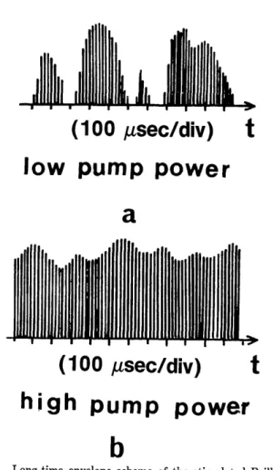
Fig. 8. Temporal structure of the backward-stimulated Brillouin
beam during ring oscillation showing a typical train of stimulated Brillouin pulses in the short-time range (200 nsec/division) where the emission is highly stable.
(100
,usec/div) t
low pump power
a
(100
gsec/div)
t
high pump power
b
Fig. 9. Long-time envelope scheme of the stimulated Brillouin pulses at a, low and b, high pump power levels.
Vol. 6, No. 3/March 1989/J. Opt. Soc. Am. B 307
(100 nsec/div)
nondepleted pumpa
( 00
nsec/div)t
depleted pumpb
.
Fig. 10. Temporal structure of the forward-transmitted pump
beam: a, without and b, with ring oscillation.
low enough (experimentally lower than 400 mW at the out-put of the argon laser) to prevent the fiber from oscillating
by its end faces the repetition-rate frequency is well stabi-lized (Fig. 8).
Nevertheless, the peak amplitude of the Brillouin pulses remains unstable, particularly near the pump threshold
(now '180 mW for the argon-laser power, much higher than for the first ring oscillator): when the observation is achieved within a long time scale (100 Asec/division), the
Brillouin output exhibits randomly distributed trains of
pe-riodic pulses. Higher power results in a partial stabilization,
with amplitude fluctuation limited to some 20%. This
fea-ture is shown schematically in Fig. 9. The mechanical
vibra-tions could be partially responsible for these instabilities,
because we already observe small amplitude fluctuations
with similar frequencies below the Brillouin threshold; we attribute these instabilities to phase fluctuations between direct and recoupled pump beams.
The Brillouin pulse width is typically 20 nsec FWHM,
with incidentally shorter pulses down to 10 nsec FWHM for
the strongest amplitudes, and that width covers all the
use-ful pump power range (roughly a factor of 2, from 200 to 400
mW at the argon-laser output). The SBS amplification is
strong enough to produce a Brillouin Stokes peak power as
much as an order of magnitude higher than the nondepleted
pump power (measured by opening the ring cavity).
Another interesting feature is the pump power depletion,
shown in Fig. 10 for the case of high pumping level. Pump
depletion is increasing with the power value and may reach
more than 50% of the average level and 85% of local level.
4. NUMERICAL RESULTS
SBS in an optical-fiber ring configuration is one of the most
striking examples of long-time nonlinear interaction of light with matter, and the dynamical evolution requires long-time numerical integration for the asymptotic behavior to be known. It may be modeled well by the one-dimensional
C3W-SBS Eqs. (5)-(7) or (11), (12), and (7) when the optical Kerr effect is included. We have performed several
numeri-cal computations for the periodinumeri-cal feedback conditions of the ring configuration and for different pump powers P given in Table 1 by using the four-step Runge-Kutta inte-gration algorithm described in Ref. 16. Even though our principal result concerns the stabilization of a pump-modu-lated fiber-ring SBS laser, we present below some results concerning the cw fiber-ring configuration to show the lack
of performance of such a setup for obtaining a stable SBS
pulsed laser, as mentioned in Section 1.
A. Constant Pump Input (Continuous Wave)
As we mentioned in Subsection 2.B, the SDA model, which
neglects the inertial response time of the phonons, cannot describe the transient regime of amplification and
compres-sion of an initial bounded condition for E2(x, t = 0) since its
tail is spread because of the finite response time of the phonons. Therefore we use the C3W-SBS equations to de-scribe the transient temporal behavior. Nevertheless, as we shall see, when the E2(x, t) envelope is spread through the
entire fiber length, the pump depletion leads to a shortening of the gain medium, the Stokes peak gives power back to its tail, and the amplitude of the Stokes pulses decreases to a
level low enough that the regime of decreasing relaxation
oscillations tending to a steady state can be roughly de-scribed by the SDA model.
The high-amplitude transient regime depends on the ini-tial conditions; in particular, the maximum amplitude of the amplified and compressed Stokes wave envelope depends on the amplitude and width of the initial Stokes noise or pho-non noise. However, starting with a large variety of initial conditions, we have obtained the same asymptotic quasi-steady state of decreasing relaxation oscillations for the Stokes pulses; this state depends only on the gain length L/A
(see Table 1) and on the feedback efficiency p, which takes
into account the losses caused by the beam splitters and the
coupling-recoupling efficiencies [here p = 0.16 = (0.5)2 (the two beam splitters) X 0.8 (the coupling efficiency) X 0.8 (the
recoupling efficiency)].
In Figs. 11-13 we show the numerical results of integration of Eqs. (5)-(7) for the ring configuration with constant pump
input (cw) for the initial conditions E8(x, t = 0) = 0 and a
bounded Stokes bump of small amplitude 1E2(X, t = 0)max = 10-6, which occupies half of the fiber length, in order to show a strong transient peak compression that is due to the SBS effect. In the optimal situation in which the backscattered Stokes pulses are isolated from the output pump mirror (e.g., through a Faraday rotator) in order to prevent backre-flection into the fiber, the boundary conditions are
Ej(0, t) = E + WJpE1(L, t), E2(L, t) = VE 2(0, t),
where Ep is the pump field amplitude coupled into the fiber and p is the feedback efficiency. The phase dynamics does not affect the SBS gain within the model described by Eqs.
308 J. Opt. Soc. Am. B/Vol. 6, No. 3/March 1989 L/A=50; p=0.16; =4; As=4x10⁻³
> ... ,.... ,,.
0 500 l100
t
L/A=50; p=O.l6; =4; A,*=4x10⁻³
_yI 11-J4 O
500 1000
backscattered envelope until the Stokes pulses overlap (Fig. 11a). Then the pump monotonically exhibits depletion a from the input end of the fiber, and the dynamics evolves to a regime of decreasing relaxation oscillations with an in-creasing of modulation frequency (Fig. 13). The result is an almost total reflector, which downshifts the pump frequency by the 34-GHz sound frequency but avoids a SBS pulsed
regime.
For the input pump powers used here, the SDA model
described in Ref. 12 for Ye = 0 yields a steady state. The
L/A=50; p=0.16; ,=4; ,e=4x10⁻³
b
0
x
t
Fig. 11. Numerical computation of the pure C3W-SBS problem
governed by Eqs. (5)-(7) for constant pump input P = 50 mW (and corresponding parameters of the second column of Table 1), and an
initial bump condition for the Stokes background of amplitude
IE2(x, 0)Imax = 10-6 and width L/2. Time evolution for the
ampli-tudes a, of the backscattered train of Stokes pulses E2(X = 0, t)I; b, of the transmitted pump IEi(x = L, t)I, which initially exhibits
strong depletion and for long times reaches a quasi-constant small
level.
(5)-(7). The pump input power coupled into the fiber is
approximately P = 50 mW, corresponding to L/A = 50 and z _ 4 (see Table 1). We can see a transient regime of strong
amplified and compressed pulses (see Fig. 11a), the ampli-tude saturation of which depends on the width of the initial bump condition, accompanied by strong depletion of the
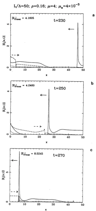
pump (Fig. lb). Figure 12 shows the envelope spatial
dis-tribution of the field amplitudes IEi(x, t)l in the fiber at
consecutive time fractions of one round-trip period Tr = 50
during the transient amplification regime. The leading backscattered Stokes pulse periodically encounters the fresh pump envelope near the middle of the fiber and exhibits noticeable gain close to the fiber input end. As we said above, for long times the inertial response of the excited phonons (finite response time) is responsible for their accu-mulation through the fiber medium, principally at the pump input end, and saturates the Stokes gain by lengthening the
0 IE2Im = 4.1605 t=230
, .
.. r--
Ad
4-4
t
0 .10 20 30 40 5 =E 21m 4.2480 t=250 4-0 10 20 30 40 5C x E2Im,, = 8.5245 t=270.4-Fig. 12. Numerical computation for the C3W-SBS ring with
con-stant pump input and the same parameters as for Fig. 1. Spatial
distribution of the field envelope amplitudes in the fiber: IEi(x, t)l (long-dashed curves), FE2(x, t)i (solid curves), and IE,(x, t)l
(short-dashed curves) at consecutive time intervals during one round-trip
period -r = 50 in the transient regime of Fig. la. a, t = 230; b, t =
250; c, t = 270. 0 0 0 -o 0 a b C 0 0 10 20 30 40 50 Botineau et al. so
Vol. 6, No. 3/March 1989/J. Opt. Soc. Am. B 309
L/A=50; p=O.16; AL=4; *=4x10⁻³ which is completely depleted at the beginning and increases
with time until it reaches an almost constant small value. In the strong-amplification regime the optical Kerr effect may become important, and in Fig. 14 we plot the numerical
results of integration of Eqs. (11), (12), and (7) for the previ-ous data and for Kr = 6 X 10⁻³. We see that self-amplitude modulation saturates the Stokes-pulse amplitude E2(X, t)I at lower values (compare it for t = 270 with that
correspond-L/A=50; p=0.16; A=4; At=4x10 3, Kr=6x10⁻³
-0
r4 R
t
L/A=50; p=O.1 6; IA=4;
IA=4xlO-0 10 20 30 40 50 X a co rI xj b
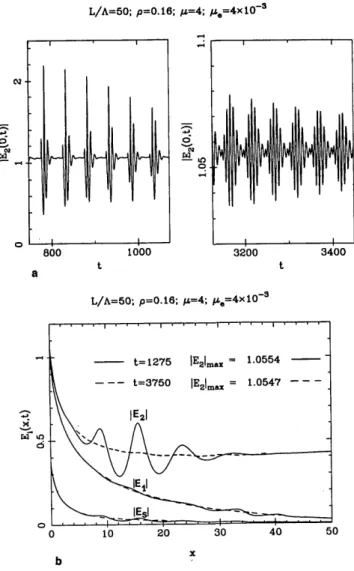
Fig. 13. a, Magnification of part of Fig. 11a at the same time interval. The maximum Stokes amplitude is of order 1 (in Ep units)
at t 1000 and at this time presents four oscillations inside one
period; it is of order 0.03 (in Ep units) at t 3400 and at this time presents seven oscillations inside one period. b, Spatial distribu-tion of the field envelope amplitudes IEj(x, t)I in the fiber at time t =
1275 (solid curves) and at time t = 3750 (dashed curves), where the
spatial envelope amplitudes tend to a monotonic quasi-steady dis-tribution.
boundary conditions for this first ring configuration
de-scribed by Eqs. (8) and (9) are given by
42(L, t) = P4,2(0, t),
Ci2
where u)in is the pump flux power coupled into the fiber and p is the feedback efficiency. For ye = O it is shown in Ref. 12
that a steady-state solution exists:
b2(0) 1 - p expgL4 1(0)[1 - 4'2(0)/'I'1(0)Il
111(0) 1-p
1-p
,1)1(0) "Din
1 - p2expjgL~b(0)[1 - 12(0)/11(0)Il
We can see from Fig. 13 that an almost steady state is approached only for long times for Ye = 0 as well as for oye F 0. We can see in Fig. lib the transmitted pump 1E1(L, t)I,
0 0
b
0 5 10 15 20
C x
Fig. 14. Numerical computation for the C3W-SBS-Kerr ring with constant pump input, taking into account the optical Kerr effect
[Eqs. (11), (12), and (7)]. Kr = 6 X 10⁻³, and the other parameters
correspond to those in the second column of Table 1. Spatial distribution of the field envelope amplitudes in the fiber: IEi(x, t)I (long-dashed curves), IE2(X, t)I (solid curves), and IE,(x, t)l (short-dashed curves) at three times separated by two round-trip periods r
= 50 around the Stokes pulse amplitude saturation. The Stokes envelopes show a fine structure. The figures represent the first two
fifths of the fiber.
a x rX x x 41(° t) = 4in + p4'1(L, t), Botineau et al. J
310 J. Opt. Soc. Am. B/Vol. 6, No. 3/March 1989 Botineau et al. L/A=40; p=0.56: c=5; /Ae=5x10-3
; Kr=0 phonons at each round trip (the third problem mentioned in
Subsection 3.B), we must turn off the pump after the output of the backscattered Stokes pulse. Therefore we maintain the periodic regime of amplified and compressed Stokes pulses by imposing on the pump intensity the strong modu-lation synchronized at the Stokes round-trip frequency.
B. Modulated Pump Input
For a modulated wave, corresponding to the second ring oscillator described in Subsection 3.B, where substitution of mirrors for the splitters yields p = 0.56 for the feedback coefficient, strong periodical variation of the pump input
L/A=40; p=0.56; =5; !,e=K=5X10⁻³ t
Fig. 15. Numerical computation for the SBS ring with modulated
pump input (without the optical Kerr effect): time evolution for the amplitudes of the backscattered train of Stokes pulses 1E2(X = 0,
t)j, which show a slow secular amplification after time t 1000. (Data from first column of Table 1 with K = 0).
C'J
S
,
L/A=40; p=0.56; IA=5; *?Se=K=5X10⁻³
1-°N a 0\ 0 700 a t 800 -a, t
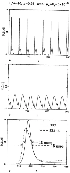
Fig. 16. Numerical computation for the SBS-Kerr ring with modu-lated (MW) pump input (with the optical Kerr effect and data corresponding to those of the first column of Table 1 with K, = 5 X 10⁻³): Time evolution for the amplitudes of the backscattered train
of Stokes pulse IE2(X, = 0, t)I, which show a saturation at time t 500. The asymptotic stage presents an amplitude E2(X, t)Imax 2.8.
ing to Fig. 12c), and the envelope shows a fine structure.
Figure 14 represents the first two fifths of the fiber. The
envelope structure looks like the experimental one shown in
Fig. 3b, which certainly indicates that the multiple-scatter-ing experimental situation maintains a highly transient
re-gime, like that of Ref. 31. However, here we do not consider
interaction between multiple backward and forward Bril-louin Stokes pulses, which were present in the actual experi-ment owing to the lack of isolation of the pump laser from the ring, and we obtain a quasi-steady-state regime.
The understanding of the saturation and relaxation mech-anism for the cw pump input case, described by the
C3W-SBS equations, leads us to look for a C3W-SBS pulsed regime. In
order to permit spontaneous damping of the accumulated
0 700 b 800 9c't 0 900 900 C t
Fig. 17. a, Magnification of Fig. 16 showing several Stokes pulses IE2(0, t)I. b, Several transmitted pump pulses E1(L, t)l showing
depletion. c, Comparative time width of the backscattered Stokes
pulse corresponding to the SBS ring of Fig. 15 (solid curve) and of the SBS-K ring of Figs. 16 and 17 (dashed curve).
.-i
(2
0
0
Vol. 6, No. 3/March 1989/J. Opt. Soc. Am. B 311 Botineau et al.
L/A=40; p=0.56; A=5; 4.=Kr=5x10⁻³
NaI
_
pulses obtained by integration of Eqs. (5)-(7). For long times the Stokes-pulse amplitude shows a small linear growth. Taking into account the optical Kerr effect
de-scribed by Eqs. (11), (12), and (7), which result is plotted in Fig. 16, we obtain an almost stable saturated regime of
backscattered Stokes pulses. Figure 17a is an enlargement
of part of Fig. 16 containing several pulses in order to show
the similarity with the experimental results and the stability of the system. The experimental behavior of the
transmit-ted pump shown in Fig. lOb, which exhibits depletion, is in good quantitative agreement with that shown in Fig. 17b.
The optical Kerr effect limits the Stokes-pulse compression, as is shown in Fig. 17c, and corresponds better to the experi-mental recording. Figure 18 shows the envelope spatial distribution of the field amplitudes IEi(x, t)l in the fiber at
two consecutive times during one period of the stabilized
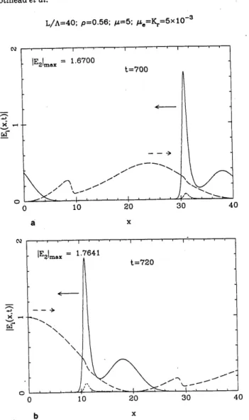
pulsed regime. a x rIlm =1.7641 0~ ~ ~ ~ ~~ =2 0 10 20 30 40 b X
Fig. 18. Numerical computation for the SBS-Kerr ring with
modu-lated pump input. Spatial distribution of the field envelope
ampli-tudes in the fiber: IEI(x, t)I (long-dashed curves), IE2(x, t)I (solid curves), and IE,(x, t)I (short-dashed curves), at two consecutive times during one period.
level by the AOM at the round-trip frequency vr = 11'r
synchronized with opposite transmission of the outgoing backscattered Brillouin pulses, determine the boundary conditions
E1(0, t) = Ep[1 + cos(2irt/rr)/2
+ f4.fE 1(L, t)[1 - cos(2rt/rr)]/2,
E2(L, t) = WJE2(0, t)[1 - cos(2irt/rr)/2
that simulate the experimental situation. f is a phase factor depending on the optical path, lying in the interval [-1, +1]. Here we arbitrarily take f = 1. The numerical results are
plotted in Figs. 15-18 for L/A = 40, t = 5, and ye = 5 X 10⁻³, which represent a peak amplitude Ep = 1.4 MV/m or a peak power of approximately P = 25 mW. Of course, the nonlin-ear SBS gain in the presence of the variable pump input is variable too, yielding a smaller mean power coupled into the
fiber. This is taken into account in the computation of the
C3W-SBS equations, for which all the dimensionless
vari-ables are parameterized to the peak amplitude Ep.
Figure 15 shows the train of backscattered Brillouin
5. CONCLUSION
A ring optical-fiber oscillator may be designed to produce,
by SBS, a quasi-periodic train of compressed Stokes pulses
amplified to several times (-10) the peak pump level. This result is obtained by modulating the pump wave coupling and the oscillator feedback by an AOM synchronized at the round-trip photon frequency. Such a device could be the basis of an all-optical-cw pumped clock if the modulator is driven by the Stokes pulse train itself.
In order to describe the dynamical evolution of this inter-action properly, we have developed a numerical model based on the coherent partial differential equations for Brillouin scattering, which permits the optical Kerr effect to be taken into account and the limitations of the more classical
inten-sity model to be known more precisely. Numerical and
experimental results agree quantitatively. Moreover, this coherent model provides the possibility of generating quasi-soliton Stokes pulses in a SBS fiber-ring laser.32
ACKNOWLEDGMENTS
The authors thank Pierre Sixou, Claude Froehly, and Henri
Le Gall for use of the experimental facilities. They also
thank Jean Coste and Olivier Legrand for stimulating dis-cussions and Roger H. Stolen for providing the fiber used in these experiments and for helpful remarks. Part of this research has been developed in the scientific program of the Groupe d'Interaction Laser-Matibre associated with the Laboratoire pour l'Utilisation des Lasers Intenses-Centre National de la Recherche Scientifique. The Laboratoire de
Physique de la Matiere Condens6e is Laboratoire Unit6 de
Recherche Associee 190, associated with the Centre
Nation-al de la Recherche Scientifique, France. C. Montes is also with the Observatoire de Nice, Bolte Postale No. 139, 06003 Nice C6dex, France.
REFERENCES
1. E. P. Ippen and R. H. Stolen, "Stimulated Brillouin scattering
in optical fibers," Appl. Phys. Lett. 21, 539 (1972).
2. D. Cotter, "Stimulated Brillouin scattering in monomode opti-cal fiber," J. Opt. Commun. 4, 10 (1983).
3. K. 0. Hill, B. S. Kawasaki, and D. C. Johnson, "Cw Brillouin laser," Appl. Phys. Lett. 28, 608 (1976).
312 J. Opt. Soc. Am. B/Vol. 6, No. 3/March 1989
Botineau et al.
4. D. C. Johnson, K. 0. Hill, and B. S. Kawasaki, "Brillouin opti-cal-fiber ring oscillator design," Radio Sci. 12, 519 (1977). 5. B. S. Kawasaki, D. C. Johnson, Y. Fujii, and K. 0. Hill,
"Band-width-limited operation of a mode-locked Brillouin parametric
oscillator," Appl. Phys. Lett. 32, 429 (1978).
6. D. R. Ponikvar and S. Ezekiel, "Stabilized single-frequency stimulated Brillouin fiber ring laser," Opt. Lett. 6, 398 (1981). 7. L. F. Stokes, M. Chodorow, and H. J. Shaw, "All-fiber
stimulat-ed Brillouin ring laser with submilliwatt pump threshold," Opt.
Lett. 7, 509 (1982).
8. A. Ya. Karasik and A. V. Luchnikov, "Generation of nanosecond radiation pulses as a result of stimulated Brillouin scattering in single-mode fiberglass waveguide," Sov. J. Quantum Electron. 15, 877 (1985).
9. I. Bar-Joseph, A. Dienes, A. A. Friesem, E. Lichtman, R. G. Waarts, and H. H. Yaffe, "Spontaneous mode locking of single and multi mode pumped SBS fiber lasers," Opt. Commun. 59, 296 (1986).
10. V. N. Lugovoy and V. N. Streltsov, "Stimulated Raman
radia-tion and stimulated Mandel'stam-Brillouin radiaradia-tion in a laser
resonator," Opt. Acta 20, 165 (1973).
11. R. V. Johnson and J. H. Marburger, "Relaxation oscillations in stimulated Raman and Brillouin scattering," Phys. Rev. A 4,
1175 (1971).
12. I. Bar-Joseph, A. A. Friesem, E. Lichtman, and R. G. Waarts,
"Steady and relaxation oscillations of stimulated Brillouin
scat-tering in single-mode optical fibers," J. Opt. Soc. Am. B 2, 1606 (1985).
13. C. L. Tang, "Saturation and spectral characteristics of the Stokes emission in the stimulated Brillouin process," J. Appl.
Phys. 37, 2945 (1966).
14. W. Kaiser and M. Maier, "Stimulated Mandelstam-Brillouin process," in Laser Handbook 2, T. F. Arecchi and F. 0. Schulz-Dubois, eds. (North-Holland, Amsterdam, 1972), p. 1077. 15. I. L. Fabelinskii, "Stimulated molecular scattering of light," in
Molecular Scattering of Light, I. L. Fabelinskii, ed. (Plenum,
New York, 1968), pp. 483-532; "Stimulated Mandelstam-Brillouin process," in Nonlinear Optics, Vol. I of Quantum Electronics: A Treatise, H. Rabin and C. L. Tang, eds. (Aca-demic, New York, 1975), pp. 363-418.
16. J. Coste and C. Montes, "Asymptotic evolution of stimulated
Brillouin scattering: Implications for optical fibers," Phys.
Rev. A 34, 3940 (1986).
17. C. Montes and R. Pellat, "Inertial response to nonstationary stimulated Brillouin backscattering: damage of optical and
plasma fibers," Phys. Rev. A 36, 2976 (1987).
18. R. H. Stolen and C. Lin, "Self-phase-modulation in silica optical fibers," Phys. Rev. A 17, 1448 (1978).
19. D. T. Hon, "Pulse compression by stimulated Brillouin
scatter-ing," Opt. Lett. 5, 516 (1980).
20. F. Chu and C. Karney, "Solution of the three-wave resonant equations with one wave heavily damped," Phys. Fluids 20,
1728 (1977).
21. R. H. Stolen and J. E. Bjorkholm, "Parametric amplification and frequency conversion in optical fibers," IEEE J. Quantum
Electron. QE-18, 1062 (1982).
22. G. Lamb, Jr., in Elements of Soliton Theory, G. Lamb, Jr., ed.
(Wiley, New York, 1980), p. 153.
23. J. Pelous and R. Vacher, "Thermal Brillouin scattering mea-surements of the attenuation of longitudinal hypersounds in
fused quartz," Solid State Commun. 16, 279 (1975).
24. D. Heiman, D. S. Hamilton, and R. W. Hellwarth, "Brillouin scattering measurements on optical glasses," Phys. Rev. B 19, 6583 (1979).
25. K. Tai, A. Hasegawa, and A. Tomita, "Observation of
modula-tional instability in optical fibers," Phys. Rev. Lett. 56, 135
(1986).
26. M. J. Potasek and G. P. Agrawal, "Self-amplitude-modulation of optical pulses in nonlinear dispersive fibers," Phys. Rev. A 36,
3862 (1987).
27. Y. S. Silberberg and I. Bar-Joseph, "Optical instabilities in a nonlinear Kerr medium," J. Opt. Soc. Am. B 1, 662 (1984). 28. K. 0. Hill, D. C. Johnson, and B. S. Kawasaki, "Cw generation of
multiple Stokes and anti-Stokes Brillouin-shifted frequencies,"
Appl. Phys. Lett. 29, 185 (1976).
29. R. H. Stolen, AT&T Bell Laboratories, Holmdel, New Jersey
07733 (personal communication).
30. P. Labudde, P. Anliker, and H. P. Weber, "Transmission of
narrow band high power laser radiation through optical fibers,"
Opt. Commun. 32, 385 (1980).
31. C. Montes and J. Coste, "Optical turbulence in multiple stimu-lated Brillouin backscattering," Laser Part. Beams 5, 405
(1987).
32. 0. Legrand and C. Montes, "Apparent superluminous quasisoli-tons in stimulated Brillouin backscattering," J. Phys. Coll. (Paris) (to be published).