HAL Id: hal-01643456
https://hal.inria.fr/hal-01643456
Submitted on 21 Nov 2017
HAL is a multi-disciplinary open access
archive for the deposit and dissemination of
sci-entific research documents, whether they are
pub-lished or not. The documents may come from
teaching and research institutions in France or
abroad, or from public or private research centers.
L’archive ouverte pluridisciplinaire HAL, est
destinée au dépôt et à la diffusion de documents
scientifiques de niveau recherche, publiés ou non,
émanant des établissements d’enseignement et de
recherche français ou étrangers, des laboratoires
publics ou privés.
Computing cross-sections of the workspace of
cable-driven parallel robots with 6 sagging cables
Jean-Pierre Merlet
To cite this version:
Jean-Pierre Merlet. Computing cross-sections of the workspace of cable-driven parallel robots with 6
sagging cables. CK 2017 - Computational Kinematics, May 2017, Poitiers, France. �hal-01643456�
cable-driven parallel robots with 6 sagging
cables
J-P. Merlet1
1HEPHAISTOS project, Universit´e Cˆote d’Azur, Inria, France e-mail: [email protected]
Abstract. Finding the workspace of cable driven parallel robots (CDPR) with sagging cables (i.e. elastic and deformable cables) is a problem that has never been fully addressed in the literature as this is a complex issue: the inverse kinematics may have multiple solutions and the equations that describe the problem are non-linear and non algebraic. We address here the problem of determining an approximation of the border of horizontal cross-sections of the workspace for CDPR with 6 cables. We present an algorithm that give an outline of this border but also rises several theoretical issues. We then propose another algorithm that allow to determine a polygonal approximation of the workspace border induced by a specific constraint. All these algorithms are illustrated on a very large CDPR.
Key words: cable-driven parallel robots,kinematics,workspace
1 Introduction
Since a few year there has been a significant renewal in the interest for cable-driven parallel robots (CDPR) who use coiling cables as actuators instead of rigid linear actuators. Beside the classical advantages inherent to a parallel structure (improved accuracy, excellent load/weight ratio) CDPR have the huge advantage to possibly provide a very large workspace with excellent lifting capacity: our MARIONET-CRANE robot with a lifting capacity of 2.5 tons has been deployed outdoor over a 75m× 35m × 25m workspace. But having such large workspace requires having very large cable lengths so that the elasticity and own mass of the cables affect the performances of the platform (positioning accuracy, stiffness,. . . ). The purpose of this paper is first to identify the factors that may limit the robot workspace and then to propose an algorithm for computing the border of horizontal cross-section of this workspace, assuming a given altitude and orientation of the platform. Workspace calculation for parallel robots with rigid legs is a well-addressed subject [7, 15] but the unilateral action of the cables, that can only pull but cannot push, intro-duces new workspace limiting factors. Numerous works have addressed the prob-lem of workspace calculation of CDPR [1, 2, 3, 4, 5, 6, 8, 10, 12, 17, 20, 22] but
2 J-P. Merlet most of them assume non deformable and non elastic cables. Discretisation-based method has been proposed for elastic cables [11] and for a simplified sagging cable model [18]. But this approach requires to assume that the inverse kinematics prob-lem has a single solution, which is not true for a complete sagging cable model [14]. In this paper we will propose a preliminary algorithm for computing cross-sections of the CDPR workspace using a realistic cable model, assuming that the orientation and altitude of the platform is fixed and that the robot has 6 cables.
2 Notations
We will assume that the output of the coiling system for cable i is a single point Ai,
while the cable is connected at point Bion the platform. We define a reference frame
R with an arbitrary origin O whose z axis is the local vertical and a frame attached to the platform (the mobile frame) with G, the center of mass of the platform, as origin and arbitrary x, y, z axis. We then consider the vertical plane that includes the
i-th cable and we define another frame Ricfor the i-th cable with origin at Ai, the
same z axis than R and a y axis that is perpendicular to the plane. The length at rest of the i-th cable will be denoted Li
0.
3 Cable model
In this paper we will use the Irvine sagging cable model that is valid for elastic and deformable cable with mass [9]. Experimental works have shown a very good agree-ment between this model and the behavior of cables classically used for CDPR [19]. This model is established in the Rci frame in which the coordinates of Aiare (0,0,0)
while the coordinates of point Biare(xb≥ 0, 0, zb). In this frame vertical and
hori-zontal forces Fz, Fxare exerted on the cable at point Bi.
The coordinate x, z of a point on this cable at the curvilinear coordinate s (in the range[0, L0]) is given by [9]: x= Fxs EA0 +Fx µ g(sinh −1(Fz+ µ g(s − L0) Fx ) − sinh−1(−µ gL0+ Fz Fx )) z=Fzs+ µ g(1/2 s 2− L 0s) EA0 + q Fx2+ (Fz+ µ g (s − L0))2− q Fx2+ (−µ gL0+ Fz)2 µ g (1)
where E is the Young modulus of the cable material, µ its linear density, A0the
surface of the cable cross-section and Fx> 0. The coordinates of B are obtained for
s= L0and are related to the forces Fx, Fzby:
xb= Fx( L0 EA0 +sinh −1(F z) − sinh−1((Fz−µgLFx0) µg ) (2)
zb= pF2 x + Fz2− p F2 x + (Fz−µgL0)2 µg + FzL0 EA0 −µgL 2 0 2EA0 (3)
4 Workspace limitations
4.1 Cable tension limit and cable sagging
An evident reason that may limit the workspace is the maximal allowed ten-sion in the cable. The maximal tenten-sion τA in a cable is obtained at point A and
should be lower than the maximal allowed tension for the cable τlim i.e. τA=
p
F2
x + (Fz+µgL0)2≤τlim.
A less obvious reason that may limit the workspace of a CDPR is that the sagging of some cable(s) may lead to have the cable on the ground. Deriving the cable model equation shows that z is extremal for s0= L0+ Fz/(µg). If s0lie in the range[0, L0]
then the cable is sagging and its minimal altitude zm is obtained by substituting s
by s0in equation (1). If zgis the ground altitude, then we should have zg≤ zo. If
s06∈ [0, L0], then the lowest point of the cable is B and we will assume that this point
cannot reach the ground.
4.2 Inverse kinematics and Singularity
A necessary condition for a pose to belong to the workspace of a CDPR is that the inverse kinematics (IK) for this pose has at least one solution in the L0’s. We
thus consider the IK of a CDPR with n cables. Being given a pose of the platform (2,3) provide 2n equation while having 3n unknowns (the Fx, Fz, L0for each cable).
Additional equations are obtained by considering the mechanical equilibrium of the CDPR. Let fi be the force exerted by the cable at point Bi by the i-th cable. We
have already seen that the components of fiin the reference frame Rciare (Fxi, 0, Fzi).
For a given location of Biit is easy to calculate a rotation matrix Ricorresponding
to a rotation around the z axis so that the components of fi in R are obtained by
Ri(Fxi, 0, Fzi)T. The mechanical equilibrium equations may thus be written as: j=n
∑
j=1 fj= mg j=n∑
j=1 GBi× fj= 0 (4)where m is the platform mass. These equations provide 6 additional constraints with-out increasing the number of unknowns. Hence we end up with 2n+ 6 for 3n un-knowns. As we assume a CDPR with n= 6 cables the IK amounts to solve a square system of 18 equations in 18 unknowns, a problem that has been addressed in [14]. It has been shown that the system may have from 0 to multiple solutions. Hence
4 J-P. Merlet a pose may not belong to the workspace simply because it has no IK solution or because the IK equations are singular. We will not make any distinction between a singular pose or a pose that has no IK solution as both forbid a pose to be part of the workspace. We will denote by outside conditions all limiting conditions that always include singularity and no IK solution while the other limiting conditions presented in section 4.1 may or may not be taken into account.
5 Workspace calculation
As determining the workspace of CDPR is a complex issue we will simplify the problem by determining only 2D horizontal cross-sections of this workspace, as-suming that both the altitude and the platform orientation are fixed.
A possible strategy to determine such a cross-section has been proposed in [13]. This strategy first relies on the solving of the IK at a given pose X0, assuming that
we are able to find a pose at which the IK has at least one solution. Then for a given IK solution Sjat X0it has been shown that it is possible to determine anεsuch that
for all pose X such that||X − X0||∞≤εthere is a single solution S of the IK such
that||S − Sj||∞≤ε. Furthermore it was also shown that the solution for a particular
X can be safely calculated with the Newton-Raphson scheme, using Sj as initial
guess. With this result we can calculate a square surrounding X0that is part of the
workspace. The process is then repeated recursively starting from the corners of the square, while a pose is rejected if theεfor this pose is lower than a fixed threshold. We thus get an approximation of the workspace as a list of boxes that are guaranteed to be part of the workspace. Although this procedure is safe, trials have shown that the maximal value ofεwas very small, leading to a very large computation time for CDPR with large workspace.
5.1 Approximate border calculation
We now describe another approach, called the approximate border calculation, which focus on determining only the border of the workspace.
First let us define a pose as out if at least one of the outside condition is satisfied. Conversely a pose will be denoted in if none of these conditions are fulfilled. We now define theαsetof a pose X (called the heart of theαset) with coordinates(x, y) as the set of 8 poses whose coordinates (xu, yu) are defined as xu= x + k1α, yu=
y+ k2α with k1, k2∈ [−1, 0, 1] excluding the case where k1= k2= 0. A pose X and
itsαset are part of the approximate border if: • at least one pose of itsα set or the pose itself is in • at least one pose of itsα set or the pose itself is out
If these conditions are fulfilled, then the pose X will be called anαpart of the border to indicate that X and itsα set are part of the approximate border. Our objective is now to compute poses that are part of the approximate border. For that purpose we assume thatα is chosen small enough so that the Newton-Raphson (NR) scheme used with as initial guess one the IK solution for X may be used to determine if • the IK has no solution or is singular (NR does not converge)
• the pose is in or out if the NR converges
Under these conditions we may determine if a pose X and itsα set are part of the approximate border, provided that we have an IK solution for this pose. Note that we associate to each pose of theαset an IK solution except that for the singular one we attach the IK solution of one of the in pose of theαset.
5.2 Propagation
Assume that we have determined a X and itsαset that are part of the approximate border (AB). Our objective is now to find other poses that belong to the AB. For that purpose we will consider each pose Xiof theα set of X and check if Xiis anαpart
of the border. Note that we have already checked the in or out status of some of the poses of theα set of Xibut this set includes new poses, the status of which has to
be determined. As soon as a newα part of the border is discovered this process is repeated. In this way we propagate the approximate border. All poses that are anα
part of the border are stored, together with their IK solution and in/out status. The propagation algorithm also maintain a list L of poses that have to be processed for completing the propagation. This propagation stops when this list is empty.
5.3 Initialization
As mentioned in the previous section it is necessary to determine at least one pose that is inside the workspace and has at least one pose in its α set that is out. For that purpose we will assume that that we have been able to determine one pose Xin of coordinates(xin, yin) that has at least one IK solution, possibly using the
algorithm proposed in [14]. We then consider the pose of coordinates(xin+ kα, yin)
where k is an integer. We start with k= 0 and increment k by 1 until the pose is out (the NR scheme is used with the IK solution obtained for k− 1 as initial guess of the solution for k). With this approach we will find k1 such that the pose of
coordinates (xin+ (k1− 1)α, yin) is in and (xin+ k1α, yin) is out: we have hence
obtained a starting point for the propagation. Note that k1may depend on the choice
of the IK solution for Xin. Other starting poses for the propagation may be obtained
similarly by considering the poses(xin− kα, yin), (xin, yin+ kα), (xin, yin− kα). All
6 J-P. Merlet After having obtained these starting poses we run the propagation algorithm for computing the approximate border. This algorithm may raise some theoretical issues but before mentioning them we will consider an example.
6 Examples
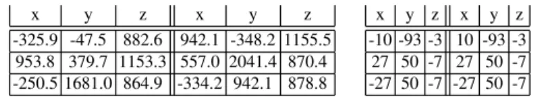
We consider as example our large scale robot MARIONET-CRANE [16]. This robot is a suspended CDPR (i.e. there is no cable pulling the platform downward) with 6 cables, whose Ai, Bicoordinates are given in table 1. The cables characteristics are
x y z x y z -325.9 -47.5 882.6 942.1 -348.2 1155.5 953.8 379.7 1153.3 557.0 2041.4 870.4 -250.5 1681.0 864.9 -334.2 942.1 878.8 x y z x y z -10 -93 -3 10 -93 -3 27 50 -7 27 50 -7 -27 50 -7 -27 50 -7
Table 1 Coordinates of the Aiand Bipoints on the base and on the platform (in cm, by rows)
E= 1009N/m2,µ= 0.079 kg/m and their diameter is 4 mm. The maximal tension
in the cables is 13734N. We start by assuming that the platform mass is 100 kg. We assume that the center of mass of the platform is at a height of 200 cm and that the platform orientation is such that the mobile frame axis coincide with the reference frame axis. Our previous work have shown that the pose with coordinates (300,800) has a single IK solution and we use it as the initialization point. First we assume that the only outside condition is the singularity for the NR scheme. Figure 1 shows the approximate border in that case.
Fig. 1 Approximate border for m= 100 and a detailled view
It can be seen that an outside border has been determined but there are several regions within the inside of the workspace. A detailed view is presented in figure 1 for x∈ [0, 1.58](m), y ∈ [10.4, 13.4](m). It can be seen that the inside regions are
of two different types: either in (for which the point on the border are in, in black on the figure), labeled I on the drawing, or out (the pose on the border are singular, in blue), labeled O. However there may be singular poses that are included in the in region. For the poses on the border the maximal tensions are 237762, 94687, 588078, 643676, 481622 and 468928 N while the maximal L0are 129613, 221416,
1517647, 236185, 445492 and 1210157 meters.
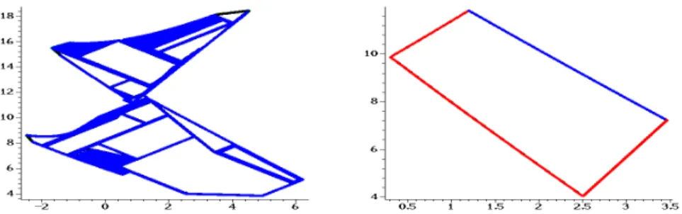
If we assume now that the cable tensions cannot exceed 13734N we get the workspace presented in figure 2. It may be seen that the approximate workspace is reduced because of the tension constraint (pose that do not respect this constraint are in black in the drawing). In that case the maximal L0are 5959, 6331, 11817,
11613, 11815 and 11813 meters. Although these values are much less than in the previous case, it may be seen that they are still very high and well over reasonable values. If we impose now that the minimal height of the cable cannot be lower than
Fig. 2 On the left approximate border for m= 100 and τ ≤13734N and on the right approximate border for m= 100 and 0 as minimal height for the cables
0 we get the workspace presented in figure 2 where 3 of the 4 border components are obtained because of this constraint (in red in the drawing) while one element is due to singularity (in blue). In that case the maximal tension in the cable are 592, 470, 377, 705, 669 and 493N while the maximal L0are 13.96, 19.09, 19.25, 20.31,
17.90 and 13.59 meters.
7 Conclusions
In this paper we have shown that the exact determination of the border of the workspace of CDPR with sagging cables is a complex issue even if only workspace cross-sections are to be determined. We have proposed preliminary algorithms that give insights on the workspace but also raise several theoretical issues that need to be furthermore considered. Other extension will be to consider cable interference and the possibility of having more (or less) than 6 cables.
8 J-P. Merlet
References
1. Barrette, G., Gosselin, C.: Determination of dynamic workspace of cable-driven planar paral-lel mechanisms. ASME J. of Mechanical Design 127(2), 242–248 ( March 2005)
2. Berti, A., Merlet, J.P., Carricato, M.: Workspace analysis of redundant cable-suspended paral-lel robots. In: 2nd Int. Conf. on cable-driven paralparal-lel robots (CableCon), pp. 41–54. Duisburg ( August, 24-27, 2014)
3. Diao, X., Ma, O.: Workspace determination of general 6 d.o.f. cable manipulators. Advanced Robotics 22(2-3), 261–278 (2008)
4. Fattah, A., Agrawal, S.: On the design of cable-suspended planar parallel robots. ASME J. of Mechanical Design 127(5), 1021–1028 ( September 2005)
5. Ferraresi, C., Paoloni, M., F., P.: A new methodology for the determination of the workspace of six-dof redundant parallel structures actuated by nine wires. Robotica 25(1), 113–120 ( January 2007)
6. Gagliardini, L., Gouttefarde, M., Caro, S.: Determination of a dynamic feasible workspace for cable-driven parallel robot. In: ARK. Grasse ( June, 27-30, 2016)
7. Gosselin, C.: Determination of the workspace of 6-dof parallel manipulators. ASME J. of Mechanical Design 112(3), 331–336 ( September 1990)
8. Gouttefarde, M., Daney, D., Merlet, J.P.: Interval-analysis based determination of the wrench-feasible workspace of parallel cable-driven robots. IEEE Trans. on Robotics 27(1), 1–13 ( February 2011). URL http://hal.inria.fr/lirmm-00573491/en
9. Irvine, H.M.: Cable Structures. MIT Press (1981)
10. Jeong, J., Kim, S., Kwak, Y.: Kinematics and workspace analysis of a parallel wire mechanism for measuring a robot pose. Mechanism and Machine Theory 34(6), 825–841 ( August 1999) 11. Korayem, M., Bamdad, M., Saadat, M.: Workspace analysis of cable-suspended robots with elastic cable. In: IEEE International Conference on Robotics and Biomimetics, 2007. ROBIO 2007, pp. 1942–1947 (2007)
12. Lim, W., et al.: A generic force closure algorithm for cable-driven parallel manipulators. Mechanism and Machine Theory 46(9), 1265–1275 ( September 2011)
13. Merlet, J.P.: On the workspace of suspended cable-driven parallel robots. In: IEEE Int. Conf. on Robotics and Automation. Stockholm ( May, 16-20, 2016)
14. Merlet, J.P.: A new generic approach for the inverse kinematics of cable-driven parallel robot with 6 deformable cables. In: ARK. Grasse ( June, 27-30, 2016)
15. Merlet, J.P.: Determination of 6D workspaces of Gough-type parallel manipulator and com-parison between different geometries. Int. J. of Robotics Research 18(9), 902–916 ( October 1999).
16. Merlet, J.P., Daney, D.: A portable, modular parallel wire crane for rescue operations. In: IEEE Int. Conf. on Robotics and Automation, pp. 2834–2839. Anchorage ( May, 3-8, 2010). 17. Pusey, J., et al.: Design and workspace analysis of a 6-6 cable-suspended parallel robot.
Mech-anism and Machine Theory 139(7), 761–778 ( July 2004)
18. Riehl, N., et al.: On the static workspace of large dimension cable-suspended robots with non negligible cable mass. In: 34th Annual Mechanisms and Robotics Conference. Montr´eal ( August, 15-18, 2010)
19. Riehl, N., et al.: On the determination of cable characteristics for large dimension cable-driven parallel mechanisms. In: IEEE Int. Conf. on Robotics and Automation, pp. 4709–4714. An-chorage ( May, 3-8, 2010)
20. Stump, E., Kumar, V.: Workspaces of cable-actuated parallel manipulators. ASME J. of Me-chanical Design 128(1), 159–167 ( January 2006)
21. Tapia, R.: The Kantorovitch theorem for Newton’s method. American Mathematic Monthly 78(1.ea), 389–392 (1971)
22. Verhoeven, R.: Analysis of the workspace of tendon-based Stewart platforms. Ph.D. thesis, University of Duisburg-Essen, Duisburg (2004)