HAL Id: hal-01330435
https://hal.archives-ouvertes.fr/hal-01330435
Submitted on 19 Jul 2018
HAL is a multi-disciplinary open access archive for the deposit and dissemination of sci-entific research documents, whether they are pub-lished or not. The documents may come from teaching and research institutions in France or
L’archive ouverte pluridisciplinaire HAL, est destinée au dépôt et à la diffusion de documents scientifiques de niveau recherche, publiés ou non, émanant des établissements d’enseignement et de recherche français ou étrangers, des laboratoires
Diffraction gratings: from principles to applications in
high-intensity lasers
Nicolas Bonod, Jérôme Neauport
To cite this version:
Nicolas Bonod, Jérôme Neauport. Diffraction gratings: from principles to applications in high-intensity lasers. Advances in Optics and Photonics, Optical Society of America, 2016, 8 (1), pp.156-199. �10.1364/AOP.8.000156�. �hal-01330435�
Diffraction gratings: from principles to
applications in high intensity lasers
Nicolas Bonod1,∗ and J ´er ˆome Neauport2
1Aix-Marseille Universit´e, CNRS, Centrale Marseille, Institut Fresnel, UMR 7249,
Domaine Universitaire de Saint J´erˆome, 13013 Marseille, France
2Commissariat `a l’ ´Energie Atomique et aux ´Energies Alternatives,
CEA, CESTA, F-33116 Le Barp, France
∗Corresponding author: [email protected]
Diffraction gratings were discovered at the 18thcentury and they are now widely used in spectrometry analysis with outstanding achievements spanning from the probing of single molecules in biological samples to the analysis of solar systems in astronomy. The fabrication of high quality diffraction gratings requires a precise control of the period at a nanometer scale. The discovery of lasers in the 1960’s gave birth to the optical beam lithography in the 1970’s. This technology revolutionized the fabrication of diffraction gratings by offering a highly precise control of the grating period over very large scales. It is surprising to see that a few years after, the unique spectral properties of diffraction gratings revolutionized in turn the field of high energy lasers. We review in this paper the physics of diffraction gratings and detail their interest for the pulse compression of high power laser systems.© 2016 Optical Society of America
OCIS codes: (050.0050) Diffraction gratings; (090.1970) Diffractive optics; (320.5520) Pulse compression; (140.3330) Laser damage; (140.7090) Ultrafast lasers.
1. Principles of diffraction gratings
Light diffraction is a fundamental and emblematic problem in optics. Diffraction gratings are optical com-ponents of major importance in the spectral analysis of light. They consist of a periodic modulation at the wavelength scale of an interface between two or more materials (see Fig.1). Their unique spectral properties rely on the fact that the light impinging on the periodically modulated surface is reflected or transmitted in specific angles only, which is not the case if the modulation is aperiodic.
The angles of propagation can be predicted by a very simple expression, the so-called grating’s law, that can take the simple form:
sin θm+ sin θi= mλ /d. (1)
in which d denotes the grating period, λ denotes the wavelength, θmand θi denote respectively the an-gles between the diffracted anan-gles, the incident angle and the normal to the surface. m is a relative integer denoting the diffraction order. When m = 0 (classically called specular order), the diffraction grating does not exhibit spectral properties and acts as a mirror. Diffraction properties appear when m 6= 0 and it can be observed that in this case, the angle of diffraction θm depends on the wavelength. This property is at the heart of the spectral analysis since plane-waves of different frequencies will not propagate in the same
x y Superstrate Substrate Modulated area h d 1st order 0 order (specular) -1st order -2nd order Θi
FIGURE 1.Sketch of a typical diffraction grating of groove depth h, period d.
direction which allow to measure the intensity of light diffracted with respect to its frequency. This property is of fundamental importance in many domains of application ranging from biology to astronomy. Blazed gratings are designed to maximize the diffracted efficiency of one specific order (with m 6= 0), which is the case of pulse compression diffraction gratings.
In a Littrow mounting, the angle of the blazed diffracted propagative order m, denoted θmis opposite to the angle of incidence θm= −θi [1]. In other words, the mth order reflected beam backpropagates in the same direction than the incident beam. The Littrow incidence can be deduced from Eq.1with θm= −θi:
2 sin θm,L= mλ /d. (2)
The Littrow incidence is interesting since high diffracted efficiencies are classically achieved near this inci-dence (i.e. to design blazed gratings), and because they permit to design very compact systems since near this incidence the angular deviation is small.
The grating’s law results from the pseudo-periodicity of the electromagnetic field and can be simply derived by considering an incident plane wave Ei× exp(ikix) impinging in a periodic modulation, where ki is the x-component of the incident wavevector. The periodic modulation means that the dielectric permittivity (or magnetic permeability in the case of magnetic materials) is periodic with respect to the x-axis, with a period d, ε(x, y) = ε(x + d, y) (see Fig.1). We assume that in linear optics, the electromagnetic response of the periodic modulation can be described by a linear operator R defined by [2,3]:
Ed(x, y) = R(x)Ei(x, y) (3)
where Ed(x, y) and Ei(x, y) describe respectively the total and incident fields. Due to the periodicity of the dielectric permittivity, the linear operator is invariant with respect to a translation of d along the x-axis :
Ed(x + d, y) = R(x + d)Ei(x + d, y) = R(x)Ei(x, y)exp(ikid), (4)
This expression shows the pseudo-periodicity of the electric (and magnetic) field due to the periodicity of the dielectric permittivity. Now, it can be easily verified that the function defined by v(x, y) = Ed(x, y)/exp(ikix) is periodic with a period d:
v(x + d, y) = Ed(x + d, y)/exp(iki(x + d)) (6)
v(x + d, y) = Ed(x, y)exp(ikid)/exp(iki(x + d)) = Ed(x, y)/exp(ikix) (7)
v(x + d, y) = v(x, y) (8)
This periodic function can be represented by its Fourier series: v(x, y) = Ed(x, y)/exp(ikix) = ∞
∑
m=−∞ vm(y)exp(i 2mπ d x) (9) Ed(x, y) = ∞∑
m=1 vm(y)exp(i(ki+ 2mπ d )x) (10)where vm(y) describes its Fourier components. We finally get: Ed(x, y) =
∞
∑
m=−∞vm(y)exp(ikmx) (11)
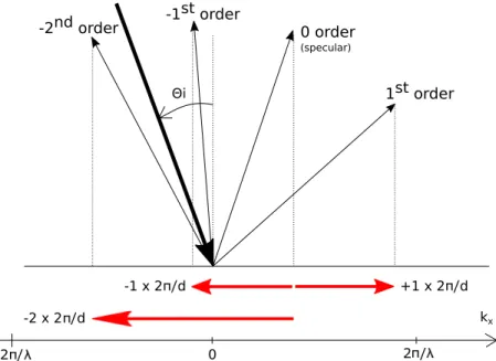
with km= ki+ 2πm/d. In a medium of refractive index ni, ki= 2πnisinθi/λ and km= 2πnisinθm/λ , from which we deduce the grating’s law written in Eq.1in the simplest case of a reflection grating with ni=nm=1. Let us remind that an infinite number of orders are diffracted by a periodic modulation and that in a medium of refractive index ni, the y component of the wavevector ky is related to km viathe expression: ky=p(2πni/λ )2− k2m. A diffractive order is propagative (resp. evanescent) if kyis real (resp. imaginary), or in other words, if |km| is smaller or equal (resp. larger) than the wavenumber 2πni/λ . The specular order (m = 0) is always propagative while the others can be either propagative or evanescent. Periodic modulations with d λ will lead to evanescent orders if m 6= 0, while the case d λ will lead to very high number of propagative orders. Blazed gratings are obtained when the periodic modulation is of the same order of magnitude than the incident wavelength. The x components of the incident and reflected wavevectors are represented in Fig.2for the specular and diffracted orders. In this example, 4 orders defined by m = −2, −1, 0, 1 propagate, the others are evanescent.
The number of propagative orders and their reflected/transmitted angles can be predicted with Eq.1. How-ever, the calculation of the energy diffracted in each order requires a complete numerical method (see section
3). Besides the parameters appearing in Eq.1, diffracted efficiencies depend on the dielectric permittivities (and magnetic permeabilities in the case of magnetic materials), groove shape, and incident field polariza-tion. The two fundamental polarizations are Transverse Electric (TE) and Transverse Magnetic (TM) polar-izations. The plane of incidence being the plane (O, x, y) in Fig.2, the electric (respectively magnetic) field is normal to the plane of incidence in TE (respectively TM) polarization. Some numerical methods allow for the calculation of the Fourier components vn(y) from which are deduced the diffracted efficiencies [2,3]. 2. Discovery and manufacturing of diffraction gratings
The first observation of the unusual light propagation through a periodic media was made by F. Hopkinson in 1786 when he observed a street lamp through a silk handkerchief stretched between his hands during a summer evening. He was surprised to observe that “the silk threads magnified to the size of very coarse wires”; but was much surprised to find that, “although I moved the handkerchief to the right and left before
0 2 / kx -2 / +1 x 2 /d -1 x 2 /d -2 x 2 /d 1st order 0 order (specular) -1st order -2nd order Θi
FIGURE 2.Representation of the propagative orders reflected by a grating (the same than that considered in Fig.1). In this example, the orders m = −2, −1, 0, 1 are propagative, i.e. |km| ≤ 2π/λ . The other orders are evanescent, i.e. |km| > 2π/λ .
my eyes, the dark bars did not seem to move at all, but remained permanent before the eye” [4]. He described his observation in a brief letter addressed to his friend and colleague David Rittenhouse. The latter, a famous astronomer, rapidly figured out that this observation was coming from an interesting phenomenon in optics and opens his letter with this comment: “The experiment you mention, with a silk handkerchief and the distant flame of a lamp, is much more curious than one would at first imagine.” D. Rittenhouse realized that the phenomenon was due to a diffraction effect and he decided to reproduce the experiment by fabricating what could be considered as the first human-made diffraction grating. For that aim, he placed about 55 parallel hairs of about 1/2 inch each on the threads of a pair of fine pitch screws. In a second step, he observed the sky through a slit. With the hairs parallel to the slit, he observed parallel lines. Remarkably, he noticed that “the red rays are more bent out of their first direction, and the blue rays less; ..., contrary to what happens by refraction” [4]. A major breakthrough occurred from the interest of Fraunhofer in both fabrication and optical characterization of diffraction gratings [5]. He figured out how important is the grating pitch in the optical performances of the gratings and he paid a large attention to the fabrication of a precise ruling engine. Independently from the earlier observations of Thomas Young [6], he noticed the cosine dependence of the diffracted rays.
This pioneering work triggered more than 200 years of steady efforts to control at a nanometer scale the period and the shape of the grating modulation. Diffraction gratings can be considered as the first optical component of the modern nanophotonics. This very dynamic field of research aims at structuring matter to tailor the electromagnetic waves at a sub wavelength scale. The development of diffraction gratings has been tightly linked with the soar of micro and nanotechnologies. The first gratings manufactured were me-chanically ruled [7–9] and most gratings used for spectroscopic applications were ruled gratings. A detailed review of mechanical ruling of gratings is available in [10,11]. The first experiments of Cotton [12] in 1901 that produced a grating by recording an interference pattern on a photographic plate followed by the advent
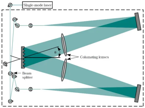
of lasers in the 1960s paved the way to the manufacturing of holographic gratings. The principle of this technique is to coat a photo-sensitive layer on a substrate (quartz or glass in general) and to create an inter-ference pattern by superimposing two coherent beams. This pattern consists of a sinusoidal modulation. The grating period is defined by the angle of incidence of the laser beams θ and their wavelength λ following the classical interference formula d = λ /2sinθ . This manufacturing step requires highly collimated beams since slight curvatures of the wavefront result in aperiodic curved grooves (see Fig.3, presenting an example of holographic set-up layout). The grating can then be used as-is (volume grating). But in this case, the index
FIGURE 3.Schematic layout of a holographic set-up, Courtesy of Lawrence Liv-ermore National Laboratory
contrast between exposed and non exposed area is low (some 0.01). Alternatively the chemical development of a (positive) photoresist removes the region exposed to the laser beams, i.e. the regions where the inter-ference between the two beams is constructive. It leads to a surface modulation of the photo-resist (surface relief grating) [13,14], hence a large index contrast (approximately 0.5). An additional etching step can be performed to etch the photo-resist and to transfer the grating resist profile into the substrate [15,16]. Overall the final grating profile can be controlled via the chemical and physical properties of the photo-resist, the time exposure of the photoresist to the laser beams, and the etching process. Each of these configurations (volume grating, surface relief photo-resin grating or bare surface relief grating) needs a specific photo-resist material and eventually a holographic set-up configuration. Most of the diffraction gratings used in high en-ergy Chirped Pulse Amplification (CPA) systems are holographic gratings. The holography technique allows one time exposure of the modulation, i. e. in principle a faster manufacturing, that is highly desirable for large surface gratings. Holographic gratings exhibit good wavefront quality, mainly related to the quality of the holographic set-up. Stray light is also reduced since random spacing errors that cannot be easily removed in ruling are negligible with optical lithography. One major issue with optical lithography is that holography records every pattern created by the interference of scattering defects such as dusts, digs and scratches on the optics used in the interference set-up. These additional interference patterns result in the superimposition
of low contrast ghost holograms on the grating modulation. The maximal size of the grating that can be manufactured by holography is limited to the size of the collimators. To avoid this issue, the scanning beam holography was developed in the early 2000’s [17] by combining the advantages of ruling and holography with recent success on large size pulse compression grating [18].
Alternatively, electron beam lithography can also be used either by direct-writing or by exposure of a photo-mask in a photo-lithography process [19]. On one hand, direct writing technique is limited to testing and prototyping of small areas since it is time consuming and not scalable to large sizes (typically larger than 10 cm2 approximately). On the other hand, photo-lithography processes in operation on 200 mm and 300 mm diameter thin silicon wafer substrates are difficult to transpose to large and thick glass substrate size. Replication process [20] can produce high diffraction efficiency and good wavefront quality gratings but the materials used for embossing (polymer, plastics...) make them unsuitable for chirped pulse amplification in high power systems.
3. Numerical methods to model light propagation in periodic media
The theoretical analysis of diffraction gratings is classically derived in textbooks within the theory of scalar optics. The diffraction grating is composed by a series of parallel and periodic slits milled into an opaque material. The diffracted orders are analyzed through the Kirchhoff diffraction theory considering each slit as a secondary source of radiation. By applying the Fraunhofer approximation, the discrete diffractive or-ders are given by the constructive interference position between the waves emitted by each source [49]. The diffracted intensity results from the product between the intensity function of a single slit and the interfer-ence function. It classically features sharp peaks due to the interferinterfer-ence function modulated by the intensity function. The former depends on the grating period while the latter depends on the geometry of the slit. However, this scalar theory failed to explain the famous spectral anomalies of light diffracted by a metal-lic grating in reflection that were first reported by Robert W. Wood in 1902 [50]. When illuminating the metallic grating in transverse magnetic polarization with a white lamp, and measuring the diffracted light with a spectrometer, R. Wood “was astounded to find that under certain conditions the drop from maximum illumination to minimum, a drop certainly of from 10 to 1, occurred within a range of wave-lengths not greater than the distance between the sodium lines” [50]. He also noticed the crucial role of the polarization since “On turning the nicol through a right angle all trace of the bright and dark bands disappeared” [50]. This discovery is of major importance in optics since, as nicely remarked by the author, “So far as I know, polarization has never been introduced into the theory of gratings” [50]. It was evident that the scalar theory could not be applied and that rigorous models based on Maxwell equations should be developed.
After several attempts, the first convincing results appeared in the late 1960s with the development of two numerical methods, namely the integral and the differential methods, together with the birth of the first computers [3]. In 1974, the integral method was successfully used to calculate the experimental efficiency curves obtained by Hutley and Bird in the visible region for a holographic grating covered consecutively with films of silver, aluminum and gold [51]. Two years later, D. Maystre and R. Petit were able to nu-merically predict a complete absorption of a monochromatic field in the optical spectrum by a metallic diffraction grating [52]. This result was confirmed a few months later by M. C. Hutley and D. Maystre when they experimentally measured the light reflection when illuminating diffraction gratings made of gold with groove depths ranging from 10 nm to 60 nm with a monochromatic light at λ =647 nm. They observed a nearly vanishing reflection for a groove depth of 40 nm. These experimental results revealing the resonant interaction of light with nanostructured metals were nicely confirmed by numerical simulations [53]. Wood anomalies contributed to pioneer the very dynamic field of plasmonics [54]. In particular, the complete light
absorption of light by metallic nanostructures lastly gained a keen interest [55–59], especially with the soar of metamaterials [60], plasmonic solar cells [61] or thermoplasmonics [62].
The development of the differential method is very interesting since this method faced several issues that were solved only at the end of the 20th century [3]. This method relies on the development of the pseudo-periodic electromagnetic fields into Fourier series. Linear Maxwell equations contain time and spatial partial derivatives. The partial time derivative can be solved by considering time harmonic fields (each frequency is diffracted independently from the others). In the case of one dimension grating, the time harmonic Maxwell equations can be separated in two different sets of equations associated to one of the two fundamental TE and TM polarizations. The spatial derivative with respect to the coordinate axis parallel to the grooves is null. The spatial derivative with respect to the coordinate axis along which the medium is periodic is calculated by expanding the pseudo-periodic fields onto Fourier series. The Maxwell equations are then reduced to a set of first order differential equations with respect to the coordinate axis perpendicular to the grating plane. This set of equations can be integrated numerically or analytically from the substrate to the superstrate. The knowledge of the incident field permits to solve the boundary conditions and to calculate the diffracted efficiencies. A second integration permits to calculate the field inside the modulated grating and to plot the field distribution at the vicinity and inside the grating.
This method was successfully applied in the 1970’s to model dielectric gratings in both fundamental po-larizations. The case of metallic gratings was more complicated to treat since the method was accurate and stable only in the case of TE polarization. Numerical computations require a truncation of the Fourier series and the convergence of the method must be ensured when increasing the number of Fourier components. The convergence is usually faster for dielectric gratings since the dielectric permittivity contrast is in this case weaker. The problems related to the poor convergence of the method in TM polarization were partic-ularly difficult to identify. Actually, two different issues were at the origin of the poor convergence. When increasing the number of Fourier components with metallic gratings in TM polarization, a second prob-lem arises due to numerical instabilities linked to the integration process. When integrating the differential system along the grating depth, a numerical contamination due to growing exponential terms occurs. The growth of the exponential terms is faster when considering a high Fourier truncation order. Consequently, both problems are distinct, but the second one becomes more important when the convergence of the method with respect to truncation order is weak. This difficulty gave birth to alternative methods of integration.
In particular, a method named Rigorous Coupled-Wave Analysis theory (RCWA) dedicated to the inte-gration of rectangular grooves was proposed in the 1980s [63]. This method is very fast and efficient since it efficiently replaces the numerical integration by an eigenvalue technique. Many efforts were then devoted to extend this approach to other groove profiles. The staircase approximation was rapidly proposed in order to apply this method to any other profile but a poor convergence was also observed in TM polarization. It was demonstrated in 2004 that the staircase approximation cannot be applied in TM polarization [64]. An alter-native method has been developed to extend the eigen value technique to other groove profiles by applying a non conformal mapping of the grating profile to a plane [65]. This method is particularly well adapted to treat smooth profiles, and its convergence is very fast for both TE and TM polarizations.
The problems related to the classical formulation of the differential method were solved in the mid 1990s. Several algorithms were successfully proposed in the 1990s to avoid the numerical contamination during the integration process for both classical differential method and RCWA method [66–70]. Solving the first problem eased the solving of the second problem related to the poor convergence of the method in TM polarization. A novel formulation of the RCWA method was proposed in 1996 to solve the convergence problem in the case of lamellar gratings [71]. The same year, L. Li clearly demonstrated that the problem was coming from the calculation in a truncated Fourier basis of a product of two functions, that is called
factorization method [72]. The convergence of the factorization is of crucial importance in a truncated basis and it can be shown easily that this convergence depends on the continuity of the functions along the coor-dinate associated with the Fourier basis. In TE polarization, the product is εEzwhich involves a continuous function (Ez) and a discontinuous function ε along x. In TM polarization, the products are εEx and ε1∂ H∂ xz which both involve two discontinuous functions. The factorization of a product h of two functions f (x) and g(x) is classically given in an infinite and complete Fourier basis by the Laurent’s rule :
hn= +∞
∑
m=−∞fn−mgm (12)
This expression can be cast in a matricial formulation by using the Toeplitz matrix [[ f ]] for which the (n, m) element [[ f ]]n,mcorresponds to the (n − m)th Fourier component. Lifeng Li distinguished 3 different cases [3,72]:
1. A discontinuous product of two functions that are not discontinuous at the same point x can be fac-torized with the “direct rule”, i.e. with the same expression as the Laurent’s rule in a truncated basis with 2N+1 Fourier components:
hn= +N
∑
m=−Nfn−mgm (13)
This the case in TE polarization where the product εEzis calculated with this formulation.
2. A continuous product of two functions that are discontinuous at the same point x can be factorized via the “inverse rule” :
hn= +N
∑
m=−N([[ f ]])−1n,mgm. (14)
This factorization expression results from the first rule applied to the discontinuous product g = 1fh. This is the case in TM polarization with lamellar gratings where the products εEx and 1ε∂ H∂ xz are both continuous.
3. A discontinuous product between two discontinuous functions cannot be factorized, neither with the “direct” nor the “inverse” rules. This is the case of the products εEx and 1ε∂ H∂ xz for gratings with arbitrary groove shapes.
The factorization of continuous and discontinuous functions in a truncated basis is a very general prob-lem and it was generalized in 2004 to other basis of functions [73] and to the case of non-linear optics in diffraction gratings [74]. The second rule permitted to understand why the formulation proposed in [71] was convergent in the case of lamellar gratings (i.e. this formulation is equivalent to the second factorization rule), and not with other groove profiles (i.e. 3rd rule).
A new formulation of the differential method was proposed in 2000 and 2001 to apply the 1st and 2nd rules of factorization to arbitrary grating profiles [75,76]. When combined with a propagation algorithm that avoids the numerical contamination, e.g. the S-matrix propagation algorithm [70], this formulation of the differential method can solve accurately Maxwell equations in deep gratings of arbitrary shape, for both TE and TM polarizations. This new formulation was applied with great success to the case of light absorption by deep metallic gratings [56]. It can be noticed that some very interesting problems were recently identified in very particular cases [77], enlightening all the richness of the grating theory.
Besides integral or differential methods, Finite Element Methods (FEM) represent a very general set of techniques to approximate solutions of partial derivative equations, such as the Helmholtz propagation equation which is at stake when tackling diffraction gratings [78–80]. Their main advantage lies in their ability to handle arbitrary geometries via unstructured meshes of the domain of interest: the discretization of oblique geometry edges is natively built in. The key ingredients to model the general case of a crossed grating illuminated by an arbitrary plane wave using FEM are (i) appropriate basis functions allowing field discontinuities (Whitney elements), (ii) Bloch boundary conditions, (iii) a way to bound the substrate and superstrate (Perfectly Matched Layers have proven to be very effective tools to that extent [81]), and (iv) an unknown satisfying a proper outgoing wave condition. A good choice is usually to calculate a diffracted field rather than the total field since it allows to bring back the sources of the plane wave within the diffractive elements as detailed in [82]. Contrarily to modal methods, the raw result given by the FEM is a 3D vector field map around the diffractive element. Diffraction efficiencies are post-processed using classical Fourier series expansion of cuts of the field taken in the substrate and the superstrate. Since the field is known everywhere, it is also possible to compute the Joule losses and to perform a self-consistent energy balance. Let us also mention other numerical methods able to model field distributions in diffraction gratings, such as the Finite Difference Time Domain (FDTD) method [83,84] or also the method of fictitious sources [85,86]. 4. Chirped pulse amplification (CPA)
The interaction between light and matter is a fundamental problem in physics and one of the most interesting topics in modern science at the boundary between different domains of expertise spanning from quantum optics, nanosciences to nuclear physics and high energy physics. Less than ten years were needed after the discovery of lasers by Maiman [21] to develop high power lasers for applications in strong light matter interactions. In this context, increasing the power of lasers becomes very important since high power lasers are promised to open new routes toward high energy physics. Milestones such as first evidence of nuclear fusion reactions by the interaction of a GW nanosecond laser and a deuterium target by Floux on the L5 laser facility at Commissariat `a l’Energie Atomique (CEA) [22], the principle of laser compression of a small deuterium tritum capsule to produce fusion reactions from Nuckolls [23] at Lawrence Livermore National Laboratory(LLNL), opened up an era of constant renewal and upgrade of high power laser facilities. With facilities such as Argus, Shiva, Nova [24], Vulcan [25], Phebus [26], Gekko XII [27], and more recently OMEGA [28], the Z-Beamlet [29] the National Ignition Facility (NIF) [30] or the Laser Megajoule (LMJ) [31], Nd:glass laser facilities have seen their energy raised from gigawatts to hundreds of terawatts with the NIF.
An important limitation is that the power of the pulse propagating inside the gain medium must stay below given thresholds to avoid non linear effects that would spoil the spatial and temporal profiles of the pulse and may also damage the laser medium. The main problem is that a decrease of the pulse duration is associated with an increase of the power. The formation of strong peak intensities inside the gain medium had limited the increase of the laser intensities until the invention of CPA in 1985 by Strickland and Mourou [32]. This technique consists of temporally stretching the input pulse before the amplification stage in order to strongly reduce the amplitude of the peak intensity in the gain medium (see Fig.4). The stretched laser pulses can be safely amplified without damaging the gain medium. The stretched amplified pulse is then re-compressed back to its initial pulse duration, giving access to short pulses and high intensities. This technique was a major breakthrough for the soar of high power lasers and offered the opportunity to break the multi-terawatt barrier.
Stretching and compressing laser pulses requires the use of dispersive optical components such as prisms and diffraction gratings. The latter are generally preferred in high power lasers because they feature higher
FIGURE 4.Principle of the Chirped Pulse Amplification, Courtesy of Lawrence Livermore National Laboratory
dispersive properties and they generate much smaller non linear effects. High energy systems generally use pairs of gratings placed in a vacuum chamber [33]. With 20 TW reached on a single beam Ti:Sa, Nd:Silicate 90 mm diameter output aperture P102 laser [34], and the PW barrier broken in 1996 on the Nova chain [35], many high intensity CPA based systems were built as upgrades of older laser facilities or brand new systems [36]. High intensity lasers offer new fields of research with fundamental studies in high energy physics but also important societal applications, from inertial fusion science, astrophysics, proton beam to radiotherapy and radiography. Many systems are thereby currently operating all around the world such as OMEGA-EP [37], Firex [38], Vulcan Petawatt [39], Petal [40], Z-Petawatt [41]...). Multi-Petawatt to sub-Exawatt facilities are also being commissioned, such as the challenging project “Extreme Light Intensity” [42]. Pulse compression diffraction gratings play a key-role in the performance of these systems and these important projects pushed diffraction gratings toward their limits in terms of size, optical performance and resistance to laser damage.
The laser damage of optical components after the compression stage, in particular diffraction gratings and mirrors for beam transport, remains one of the main limitation to the maximal output energy of lasers. The designers of compressor systems usually try to use large gratings at high incidence in order to limit the surface fluence. There are two main limitations to this strategy: (i) the size of the compressor system, especially for large bandwidth pulses, and (ii) the size and the weight of the gratings. The maximal size of pulse compression diffraction gratings does not exceed a meter approximately (see Fig.5). Let us remind that this size (∼ 1m) is impressive since it is approximately 106 times larger than the period of the grating (∼ 1µm). The manufacturing and control of such large optical components are particularly challenging. It becomes difficult to preserve the wavefront quality and the optical device becomes heavy and thereby difficult to handle during maintenance, which drastically increases the operation cost. Some groups have proposed to tile gratings [43] or to use beam phasing [44] to overcome this limitation.
FIGURE 5.Photograph of two large area 1780 lines/mm diffraction gratings (420 mm x 450 mm) used at high incidence in a pulse compressor for the high energy PETAL laser [40]. Diffraction gratings made of dielectrics, see section6.1.b
The diffraction efficiency is also an important specification since it will strongly influence the final energy delivered by the laser system. A standard compressor uses 4 gratings, hence the beam energy is reduced by η4 where η is the grating diffraction efficiency in the considered order, when passing through the com-pressor. A 90% grating diffraction efficiency corresponds to a final transmission of 66% of the energy. Consequently, diffraction efficiencies as close as possible to 100% over the spectral bandwidth are sought. This high efficiency can be very challenging to achieve over the whole spectral bandwidth, especially with short pulses for which the spectral bandwidth can be larger than 100 nm. Finally, given that small focal spots as well as high spatial and temporal contrasts on target are needed on these facilities, the wavefront quality of these gratings has to be improved on large, mid and small spatial periods. Thus there is ample evidence that operation and upgrade of current CPA systems as well as commissioning of new multi-Petawatt and sub-Exawatt facilities dramatically push grating technologies forward.
To address these different challenges, several types of diffraction gratings can be used. We wish to cate-gorize them for a better readability. Dividing diffraction gratings into strict classes is difficult. Several terms can be found which relate either to the manufacturing process (ruled gratings, holographic gratings, master gratings, replica gratings), the nature of the modulation (surface relief gratings, volume gratings), or the optical configuration (transmission gratings, reflection gratings), ... [11,45].Figure 6presents the different types of diffraction gratings found in these CPA systems following the classification proposed by Loewen and Popov [11] and also retained by Britten [46]. It separates transmission from reflection gratings on one hand, and surface relief gratings from volume gratings on the other hand. The former consists of a mod-ulation obtained by a physical corrugation of a surface whereas the latter consists of an index modmod-ulation of the bulk of a photo-sensitive material (see Fig.7). Absorption of the optical radiation being a common cause of losses and ultimately of LIDT [47], diffraction gratings obtained by a variation of the incident light amplitude through a modification of the absorption cannot be used for CPA applications and do not appear
in this classification. Diffraction gratings Reflexion Volume Photosensitive gelatin/polymer gratings Photosensitive glass gratings Surface relief Metal gratings Mulilayer Dielectric gratings Hybrid gratings Total internal reflexion gratings Transmission Volume Photosensitive glass gratings Photosensitive gelatin/polymer gratings Surface relief
FIGURE 6.A classification of diffraction gratings commonly used in pulse com-pressor systems
Overall, pulse compression gratings need to exhibit high efficiencies, to induce low wavefront distortions and to sustain high fluences. Most of the systems operate in the infrared since Ti:Sa and Nd:YAG centered respectively at 800 nm and 1053 nm are the most widespread solid materials in short pulse lasers. These performances shall be obtained on a spectral bandwidth in the range of 10 nm up to 200 nm depending on the laser system and pulse duration considered.
Before reviewing the performances of these different gratings for CPA applications, we will provide an overview of the laser damage testing protocols since it is of particular importance for high power laser systems. We then survey the challenges associated with the realization of each type of diffraction gratings. Reflection gratings are described in Section6, transmission gratings in Section7.
5. Laser-induced damage of optical materials
When a high intensity laser beam is transmitted or reflected by an optical component, the optical material may exhibit irreversible changes in the form of local defects such as craters, digs, bulk bubbles, bulk filamen-tation, melting, change in surface coloration,...These laser damage sites may spoil the optical performance of the component by scattering light and in some cases may induce damage on other downstream optical components of the laser chain. Moreover, under iterative laser shots, damage may grow to reach millimeter
(a) (b)
FIGURE 7.(a) Volume grating: a 2400 lines/mm transmission grating in dichro-mated gelatin, microscope image of the gelatin surface topology. (b) Surface relief reflection grating: a 1780 lines/mm multilayer dielectric grating and correspond-ing surface profile (scanncorrespond-ing electron microscopy image adapted from [48]).
to centimeter size imposing to change the optical component. This laser-induced damage issue has been identified on the early laser systems [87,88] and has since been the topic of intense research [89–92].
Examples of laser damage sites observed on a 802 lines/mm fused silica transmission grating in a nanosec-ond regime and a 1780 lines/mm pulse compression multi-dielectric (MLD) grating in short pulse regime are presented in Fig.8. Local or bulk absorptions, local field enhancements, Kerr effect, thermal mechanisms are likely to be the main physical effects at the origin of laser damage depending on the type of optical material, and the characteristics of the laser (wavelength, continuous or pulsed laser, pulse duration) [94]. Surface scratches or digs can for example cause local field enhancements, these scratches and digs may also trap pollution coming from manufacturing process and thus create local absorbing sites that may also further lessen the damage threshold [95,96]. In the case of a metallic mirror, intrinsic absorption of the metallic reflective layer induces thermal effects that can cause the ruin of the material [97].
While nanosecond laser interactions are usually complex sequences of absorption, plasma formation, heating and propagation of a hydrodynamic front, the case of shorter pulse interactions appears to be “sim-pler” since pulse timescale is too short to observe a thermal process during the pulse. In the case of di-electrics, damage in short pulse regime is understood as an electronic process. Free electrons are created in the conduction band by a multi-photonic absorption and impact ionization. Free-electron densities higher than (1020−22/cm3) will lead to a damage of the material. As a result, the damage behavior of optical mate-rials is “described” as more deterministic. Figure9presents a typical example of a damage probability curve
(a) (b)
FIGURE 8.(a) Edge of a laser damage created by a 1064 nm, 6 ns single laser shot at an incidence of 25◦, TE polarized, on a 802 lines/mm fused silica transmission grating. (b) Laser damage created during a R-on-1 testing protocol at 1053 nm, 30 ps on an ARC MLD pulse compression grating [93].
obtained with fused silica. Furthermore, the knowledge of the intrinsic material properties allows a good prediction of the damage behavior. For example, it has been evidenced that the band gap and pulse duration of an oxide film determines its threshold fluence by a simple phenomenological formula [99]. In the case of metals, absorption creates heat and damage occurs when the temperature of the metal reaches the melting point [97]. As a consequence, short pulse gratings must be optimized first by choosing high intrinsic damage threshold materials (if possible). In a second step, stack and/or groove geometry has to be adapted to reduce the electric field in the complete structure, and in particular on the low threshold materials.
Most of the damage testing protocols consist of a measurement and estimation of the resistance to laser damage. They are expressed in terms of Laser Induced Damage Threshold (LIDT) in J/cm2. The threshold is usually given in the beam normal, while the testing is carried out at the operating incidence, wavelength and polarization of the system. Different testing protocols exist. The 1-on-1 test consists in recording one site to a single shot at a given fluence and in increasing the fluence from 0% to 100% of damage probability. S-on-1 test is the same protocol but each site is illuminated by S laser shots having the same features. This testing protocol provides insights of potential fatigue effects. The R-on-1 testing protocol consists in ramping the fluence on each site until damage occurs. This latter testing method can evidence some conditioning effects. 1-on-1 and S-on-1 protocols are described by the ISO11254-1,2 standards respectively and more details on testing methods can be found in [94]. A particular attention must be paid when comparing the damage threshold data obtained from different testing facilities since the damage detection systems can largely impact the measured thresholds.
The laser induced damage threshold depends on the pulse duration. More precisely, it decreases when the pulse duration decreases since in this case the intensity increases. Authors have tried to establish pulse scaling laws in short pulse regimes. Mero demonstrated a τ0.33 scaling law in ion beam sputtering coating monolayers of different dielectrics for pulse durations ranging from 30 fs to 1 ps. More recently, Alessi measured a τ0.22 law on multi-dielectric pulse compression gratings etched in the silica layer (see Section
6.1.b) [93]. In the case of metals, the LIDT is independent of the pulse duration [97]. Such rules of thumb can be useful when the LIDT of different components tested at different pulse durations must be compared.
FIGURE 9.Damage probability vs peak fluence for various pulse durations at a wavelength of 800 nm, fused silica sample (Reproduced with permission from [98]. Copyright 2015, AIP Publishing LLC).
This deterministic behavior and the fact that threshold measurements are mainly used shall not mini-mize the impact of rare and localized defects on the lifetime of optical components in short pulse regime. Scratches, digs, or any structural defects that might locally enhance the electric field can initiate damage sites. Nodules existing in multi-dielectric mirrors can for example dramatically decrease the intrinsic mirror threshold [100]. The aforementioned classical testing methods used to estimate the LIDT are inefficient to take into account such rare events since the area considered for the damage testing are too small. Raster scan tests shall be preferred for this purpose [101] and this technique was recently successfully used in the sub-ps regime [93,102].
6. Reflection gratings
6.1. Surface relief gratings
6.1.a. Metal gratings
Historically, metallic diffraction gratings were the first to be considered to design reflection gratings. Metals can naturally reflect light with a good efficiency and by periodically structuring the surface of the metal, diffracted orders appear in reflection [11]. The number of orders depends only on the incident frequency, angle of incidence and period of the grating (see section 1). Blazed diffraction gratings being designed to optimize the diffracted efficiency of a specific order, these parameters are generally chosen in order to have only one dispersive propagating diffractive order in addition to the non dispersive specular order. In oblique incidence in a medium of refractive index ni, the x component of the incident wavevector satisfies 0 < ki< 2πni/λ . When the period d → 0, only the specular order m=0 propagates. When increasing the period from zero, the first dispersive order to propagate is the -1storder (see Fig.2). In most CPA applications, diffraction gratings are then designed to feature two diffractive propagating orders, namely the -1st and the 0th order, all the other orders being evanescent. For a reflection grating used in a first-order Littrow mount (m = −1), the angle of incidence being sinθi = λ /2d (see section1), these conditions occur when 2 > λ /d > 2/3. In a second step, the grating profile must be designed in order to diffract most of the incident
energy into the -1stdispersive order (blazed grating). Gold is usually preferred for metallic reflective gratings due to its high reflectivity over the spectral range of interest (700 to 1200 nm) [103] in which many laser systems operate. Besides its high optical performances, it is also a noble metal that does not require a protective transparent oxide layer like silver or aluminum.
As a first approximation, the diffracted efficiencies can be predicted by the so-called equivalence rule [104]. This rule applies when only two orders propagate and when the grating profile is symmetric, which is the case of sinusoidal, lamellar and echelette gratings with a 0.5 filling ratio. In the latter case, the grating profile can be developed onto Fourier sine series and the equivalence rule predicts that the efficiency is determined by the 1st Fourier component of the grating profile. The most interesting prediction of this theory is that different grating profiles (lamellar, echelette or sinusoidal) with similar 1st Fourier harmonic will exhibit similar diffracted efficiencies. The accuracy of this prediction is better for shallow gratings and drops for deep gratings. Moreover, diffracted efficiencies depend also on the dielectric permittivities of the grating so that accurate predictions require the use of numerical codes able to solve Maxwell equation in periodic media (see section3).
(a)
(b)
FIGURE 10. (a) Reflected efficiency in the -1st order in TE and TM polariza-tion with respect to the grating depth in micrometers. Gold grating with a sinu-soidal shape and 1550 lines/mm at a wavelength of 1550 nm (taken from [105]). (b) Diffraction efficiency (m = −1, TM polarization) of a 15-cm-diameter 1480 lines/mm Au master grating measured at wavelengths of 805, 830, 946, and 1053 nm (grating 7-27-1). The solid curve is the theoretical diffraction efficiency based on the profile (taken from [106])
Since the pioneering works of R. Wood, it is well known that metallic gratings are highly sensitive to the incident polarization. The so-called Wood’s anomalies are observed only in TM polarization since they are related to the excitation of surface plasmon polaritons. However, numerical simulations show that outside the domain of resonance, i.e. when surface plasmon polaritons are not excited, the TM polarization is as-sociated with high diffracted efficiencies [105,106]. Figure 10ashows the diffracted efficiency in the -1st order of a gold sinusoidal grating illuminated in the Littrow incidence at 1053 nm for both TE and TM polarizations with respect to the groove depth. It can be observed that the numerical predictions fit well with the experimental measurements, in particular for shallow gratings, and that the first maximum is achieved in
the case of TM polarization. The TE polarization can also lead to high diffracted efficiencies but for deeper grooves. Remarkably, both polarizations offer diffracted efficiencies in the -1storder that can be larger than the reflected efficiency of light in the bare corresponding metal. This result proves that absorption losses inherent to the use of lossy optical materials can be significantly limited in the case of metallic gratings. It also highlights that metallic gratings will be easier to manufacture in TM polarization. Hence metallic gratings used in CPA systems operate in TM polarization.
A remarkable property of metallic gratings illuminated in TM polarization is the large spectral tolerance of their reflected efficiency, as illustrated in Fig.10b. This property is of crucial importance to re-compress short pulses that feature a broad spectrum. However, this major advantage is counter-balanced by their relative weak laser induced damage threshold. As aforementioned in Section2, a solution to push back this severe limitation is to fabricate large gratings that are illuminated at high incidence in order to decrease the irradiance of the beam. Manufacturing and handling capacities limit the size of gratings to one meter. Metallic gratings used in CPA systems are fabricated by holographic technique. The grating profile can be either a photo-resin modulation or a bare substrate modulation obtained by ion etching. A metallic film is then evaporated or sputtered on the grating profile. Its thickness must be at least significantly larger than the skin depth of the metal in order to prevent a transmission of light through the metallic film to the substrate [105,107]. The homogeneity of the metallic coating is of crucial importance for both optical performances and LIDT (see Fig.11).
FIGURE 11.(a) SEM image of the conventional sputter-coated grating exhibiting a non-conformal groove structure that will decrease the diffraction efficiency. (b) SEM image showing the energetic sputter-coated grating with a more uniform groove structure, from Plymouth Grating Laboratory. Non conformal sputtering changes the field repartition and thus decreases the threshold [107].
As already mentioned, gold is usually used for the metallic overcoat [97,105]. Laser damage of metallic gratings is mainly governed by the damage of the metallic layer. Stuart et al. measured damage thresholds of 0.6 J/cm2in the input beam normal at 1.053 nm on gold coated optics [97]. They established that this value was nearly independent of the pulse duration in the short pulse regime and of the metallic film thickness. Calculations using heat conduction equation showed that this thickness invariance in short pulse regime was due to the fact that the thermal wave cannot penetrate deeper than 10 nm at this time duration. The threshold decrease under 100 nm of thickness is attributed to defects in thick metallic films (see Fig.12a). Similar damage thresholds were measured on a 1480 lines/mm gold grating with 0.4 J/cm2 in the beam normal at the wavelength of 1.053 nm (see Fig.12b).
More recently, Poole et al. [107] measured similar values on gold coated 1480 lines/mm gratings for pulses ranging between 30 fs and 200 fs. They also linked the non-conformal groove profile induced by
(a) (b)
FIGURE 12. (a) Measured damage thresholds and predictions of gold films at 1053 nm beam normal for short pulses duration of 600 fs (triangles) and long pulses duration of 800 ps (circles). (b) Effect of pulse duration on the damage threshold at 1053 nm beam normal of a 1480 lines/mm gold grating and a gold mirror (from [97])
the metallic film overcoat to the decrease of both damage threshold and diffraction efficiency. Interestingly enough, a silver coated grating exhibited about 10% higher damage thresholds. Despite this slight advantage, the use of silver coated grating is still limited since it tends to tarnish over time (explaining why silver mirror surfaces are usually protected with a silica layer).
Metallic gratings are nowadays commercially available and are proposed by several companies for CPA applications either in small or large sizes. With typical diffraction efficiencies of 92% in TM, broad band-width, these large gold gratings were successfully used and are still in use on many Petawatt laser sys-tems [36,107–111]. They are commonly used on high power laser systems, some of them delivering pulse as short as 10 fs approximately. But with a damage threshold limited to some hundreds of mJ/cm2, and a maximal size of about a meter, an alternative has to be developed to reach higher intensities.
6.1.b. Dielectric gratings
Principles Dielectrics offer two advantages for CPA applications compared with noble metals: (i) they can feature negligible losses which can be of high importance to achieve almost perfect optical performance, i.e. nearly 100% of diffraction efficiency, (ii) they feature much higher LIDTs than metals [108], which could break a barrier in the design of diffraction gratings with high thresholds for laser damage. However, dielectrics feature very different optical properties from metals so that a particular strategy must be followed in order to design an all-dielectric grating.
The concept of all-dielectric gratings to increase the resistance to laser damage was first proposed in 1991 and 1994 by Svakhin et al. considering a diffraction grating on top of an optical resonator [113,114]. The first objective was to increase the resistance of the grating to the optical pulses by designing an all-dielectric grating. It was proposed to associate a multilayer dielectric mirror consisting of an alternate of dielectric films of high (nH) and low (nL) refractive index, to a dielectric grating etched on the top layer (of low or high refractive index) (an example of an all-dielectric grating is displayed in Fig.13). Multilayer dielectric gratings can host guided modes that will drive to anomalies in the spectral properties of gratings. This problem can be avoided by determining suitably the grating pitch that will prevent the excitation of guided
FIGURE 13.All-dielectric gratings. (a) Sketch and principle as proposed in 1995 by Perry et al. (taken from [112]). Dielectric thin films of high (dark) and low (bright) refractive index are alternatively deposited on a transparent substrate. The grating profile is etched on the top dielectric layer. (b) Scanning Electron Mi-croscopy image of a top area of a multilayer dielectric grating. The modulation is etched in the silica top layer, with a trapezoidal shape (line density=1780 l/mm). (c) Distribution of the electric field intensity |E|2in the top area of an all-dielectric grating illuminated in oblique incidence (θ = 77.2◦, λ = 1053nm). The field in-tensity is classically maximal between the grooves. (Reproduced with permission from [48]. Copyright 2015, AIP Publishing LLC)
waves in multilayered devices [11]. The conditions can be simply derived by reminding that the -1st order must propagate:
sin θi− λ
d > −1 (15)
and that the -1st and +1st orders must not couple to a guided mode in the highest refractive index of the multilayer nH: sin θi+ λ d > nH, (16) sin θi− λ d < −nH (17)
By assuming a Littrow mounting with the -1st order, sinθi= λ /2d (See eq.2), we finally get: nH
3 < λ
This period range can be expanded by decreasing the refractive index of the high refractive index. The difficulty is that a decrease of the refractive index contrast will necessitate an increase of the number of layers to preserve a high reflectivity of the multilayer.
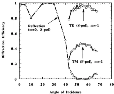
FIGURE 14.Diffraction efficiency in the -1storder experimentally measured with respect to the angle of incidence at 1053 nm in the case of a grating consisting of ZnS (n=2.35) and ThF4 (n=1.52) layers. The grating is etched in the high index (ZnS) layer with 1550 lines/mm (from [112]).
The first theoretical calculations showed that diffracted efficiencies higher than 98% in the -1st order could be achieved in TE polarization. In contrary, reflected efficiencies not exceeding 50% were predicted in TM polarization. Experimental measurements displayed in Fig.14for both TE and TM polarizations for the 0th and -1st orders confirmed these predictions and the best suitability of all-dielectric gratings for TE polarization. A similar concept was also proposed later by Perry et al. [112].
Laser damage resistance The first results were very encouraging since measurements of laser damage evidenced significant increases of the LIDT. The spectral tolerance was narrower than that typically achieved with metallic gratings and dielectric gratings were first considered for compressing pulses with time duration longer than some 100 fs. The angle of incidence was also maximized in order to decrease the power per surface unity. However, it was also evidenced that the angle of incidence was also influencing the local enhancement of the electric field intensity. In 2003, J. A. Britten et al. measured the damage thresholds of a 1800 lines/mm MLD grating under variable incidence θ . They calculated numerically the field intensity distribution for each incidence and they observed that the damage threshold was slightly better fitted with an 1/E2law than with a simple 1/cosθ area projection [117]. The first evidence of damage initiation on the grating pillar opposite to the incoming beam was also reported in this contribution.
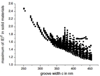
This result was followed by two numerical studies in 2006 that aimed at optimizing the grating profile to minimize the near field enhancement. N. Bonod and J. Neauport calculated in [115] the diffracted effi-ciencies and field intensity enhancements for a 1780 lines /mm grating etched in silica for different grooves
FIGURE 15.Maximum of the electric field intensity enhancement with respect to the groove width for a 1780 lines/mm diffraction grating etched in silica. The field intensity drops from 2.5 for narrow grooves to 1.15 for wider grooves. This result highlights the importance of the grating design on the near field intensity, and thereby on the LIDT, from [115].
when considering a trapezoidal profile. The calculations were performed with respect to the groove width, groove height, and slope of the inclination of the pillars. They showed that among all the profiles offering reflected efficiencies in the -1st order, the electric field intensity in the grating pillars (made of silica) was experiencing an important drop when maximizing the groove width. They reported a drop of the maximum field intensity from 2.5 to 1.15 by simply increasing the groove width while considering a constant period (1780 lines /mm) (see Fig.15). The importance of the groove shape was also highlighted a few months later by Liu etal. in the case of lamellar MLD gratings [116].
These numerical results were followed in 2007 by experimental investigations that aimed at quantifying the role of the grating profile on the final LIDT. Several MLD gratings were manufactured with different groove profiles. All the gratings were featuring reflected efficiencies in the -1st order around 96%. The profile of the etched gratings was estimated by Atomic Force Microscopy (AFM). The field distribution was thereby computed for each grating to calculate the maximum field intensity in the grating pillar (Fig.16a). In a second step, the LIDT was measured on the same zones than those probed by AFM. This methodology permitted to plot the LIDT with respect to the inverse of the maximum field enhancement 1/|E|2estimated for different grating profiles. The results displayed in Fig.16b show a linear dependence between the LIDT and 1/|E|2 which proves that different gratings exhibiting similar far field optical properties can feature highly different LIDT due to the different near field distributions. This macroscopic study was confirmed in 2011 by microscopic studies of damage morphology [48]. By observing damage with Scanning Electron Microscopy (SEM), Hocquet et al. were able to show that damages initiate at the pillar edge, at the opposite side from the incident beam, where the electric field intensity is maximum. They also observed the formation of ripples with a period of ≈ 2 µm along the groove axis. The ripples create local and periodic enhancement of the electric field that initiate damage [48].
Regarding the laser resistance, LIDT ranges from about 2.5 J/cm2 for a 1780 lines /mm grating at 1 ps pulse duration and 77.2 ◦ of incidence [119] to about 4 J/cm2 at 0.5 ps pulse duration for the same type of grating [118]. These previous results were measured in air while such CPA gratings operate under
FIGURE 16.Dielectric 1780 lines/mm gratings. (a) Field enhancement distribu-tion for large and narrow pillars, (b) effect of the field enhancement in the pillars on the damage threshold in beam normal at 1053 nm, pulse duration of 500 fs of 1780 lines/mm gratings, from [118].
vacuum. The effect of vacuum on LIDT for dielectric pulse compression gratings was thereby evaluated with some discrepancies in the conclusions. While some groups reported no effect when switching from air to vacuum [120], other groups did see an improvement [93] or a degradation [118] of the LIDT. The presence of pollution and organic contamination in gratings plays a significant role in the final LIDT. This point will deserve further studies to improve the technology of grating manufacturing and offers good potential to further increase the LIDT [121].
As explained in Section5, localized defects can significantly decrease thresholds and are evaluated by raster scan. Alessi et al. recently reported damage densities as high as 100 damages/cm2 at 4 J/cm2 in normal beam, incidence of 76.5◦, pulse duration of 30 ps, for 1740 lines/mm gratings [93]. These low damage fluences are likely to be induced by coating defects and their reduction is one of the main task to be addressed in a near future to improve the damage threshold of all-dielectric gratings.
Wavefront quality Wavefront is an important characteristic of pulse compression gratings. Since two to four gratings are used in a laser beam, they can significantly distort the diffracted beam and thus degrade the focal spot quality as well as compressibility of the output pulse. Diffracted wavefront quality of λ /3 at 1053 nm was obtained on clear aperture of a meter scale MLD gratings [18], λ /5 to λ /4 at 1053 nm can be obtained on half-meter scale optics. Interestingly enough, to decrease such aberrations (significantly larger than those of classical transmissive or reflective optics), the concept of deformable gratings was proposed. A 9 actuators design leads to a residual wavefront error of RMS = 0.015 λ , PV = 0.09 λ [122]. Other strategies using deformable mirrors are also used to compensate the grating wavefront deformation. As an example, the PETAL facility uses for this purpose a segmented mirror and two cylindrical (horizontal and vertical axis respectively) deformable mirrors to compensate for curvature and astigmatism. [123]
FIGURE 17.Crazing due to coating stress on a H f O2/SiO2E-beam Phase Vapor Deposited mirror stack,from [124].
6.1.c. From dielectric gratings to hybrid metallo-dielectric gratings
Principle One of the first difficulty faced during the early development of large dielectric gratings was the presence of mechanical stress between the thin dielectric films of high and low refractive index and also between the stack and the substrate. The mechanical stress increases with the number of bilayers and can lead to crazing at the surface of the grating [125] (see Fig.17). This problem is particularly important in the case of large size dielectric gratings and is enhanced when using fused silica substrates. Two strategies have been followed to solve this problem. First, the mechanical stress can be reduced by optimizing the coating process parameters (partial pressures) and/or adding an ion assistance to get denser coatings... Second, they can be reduced by decreasing the number of bilayers. The reflectivity of the multilayer stack can be preserved by inserting between the substrate and the dielectric multilayer a metallic film [115]. The metallic layer completes the reflection of the incomplete dielectric stack so that the hybrid metallo-dielectric stack features almost perfect reflectivity. Moreover, this hybrid design appeared later to offer new degrees of freedom to broaden the bandwidth of the grating. This is now the main advantage of this type of grating as well as an increased threshold compared to gold gratings.
Laser damage resistance The first hybrid metallo-dielectric mirrors were fabricated and characterized in 2009 in terms of optical performance, LIDT and mechanical stress [124]. The multilayer consisted of a gold layer deposited on a pyrex substrate (with an adhesion chromium layer), and SiO2 and H f O2 layers evaporated directly on the gold layer. The reflectivity was as high as that obtained with all-dielectric mirrors but its spectral and angular tolerance was wider. Importantly, the damage measurements showed LIDT values similar to those measured on mirror stack of MLD gratings [124].
The mixed metallo-dielectric gratings (MMLD) were proposed one year after [126]. The multilayer was consisting of a Au − (SiO2/H f O2)4− SiO2on 120 mm × 140 mm × 15 mm Pyrex substrates and the 1780 l/mm gratings were etched in the top silica layer. Both MLD and MMLD were fabricated with the same technology, i.e. similar substrate, thin film coatings deposited using Electron Beam Physical Vapor Deposi-tion (EBPVD) process. The two diffracDeposi-tion gratings, MLD and MMLD, were exposed to a few air/vacuum cycles (1 Atm, ambient temperature, 5.10−6mBar). After a few cycles, an observation of the grating sur-faces with an intense fiber lamp revealed the appearance of a few fractures on the MLD grating only. The optical measurements reported diffracted efficiencies in the -1st close to 97%, which is comparable to the diffracted efficiencies reported in the literature for MLD gratings. The etching profiles were then measured
by AFM which allowed for a numerical estimation of the electric field intensity enhancement in the pillars made of silica. The LIDT measurements performed at 1057 nm and 500 fs showed an affine dependence to 1/|E/E0|2. A LIDT higher than 3.5 J/cm2was measured in the beam normal, which proves the validity of the concept of hybrid metallo-dielectric gratings for the pulse compression in high power systems [118].
(a)
(b)
FIGURE 18. (a) Sketch of a large bandwidth dielectric grating with 3 layers etched. (b) Measured (circles) and simulated (dotted line) diffracted efficiency in the -1st order, 1740 lines/mm grating, a 40 nm spectral bandwidth is obtained
(from [127]) .
Spectral tolerance, from all-dielectric to hybrid metallo-dielectric gratings 20 years after their devel-opment, MLD gratings with extremely high optical performance are used in several pulse compressors and in interferometry where diffracted efficiencies as high as 99.6% were reported by Bunkowski et al. and Lu et al.[128,129]. The main issue that they face is linked to the spectral tolerance for ultrashort pulse appli-cations. The spectral bandwidth and pulse duration of CPA systems are related by the following expression :
∆t.∆λ = 2.ln(2)λ 2 0
π .c (19)
where ∆t and ∆λ denote the spectral bandwidth and pulse duration respectively, λ0denotes the wavelength, and c the light velocity. For example, for a wavelength of 1053 nm, a 200 nm bandwidth is needed to compress the pulse down to 8 fs. Consequently, the widening of the tolerance of dielectric gratings has gained most of the efforts over the last 10 years. It was suggested in 2007 to etch the grating on the high refractive index to improve the spectral tolerance [130,131]. One of the nicest achievement in the design and fabrication of diffraction gratings was obtained by Martz et al. who increased the contrast between the different materials of the multilayer and by etching the grating in different materials [127] (see Fig.18a). The grating was etched with a line density of 1740 lines/mm and was designed to operate at 10◦from the Littrow incidence (≈ 45◦) (input and output operating angles of 35◦ and 55◦ respectively) at the central wavelength of 800 nm. The multilayer stack was composed of SiO2and (Nb0.5Ta0.5)2O5acting as the low and high refractive index materials respectively deposited on a 229 mm × 114 mm fused silica substrate. The thicknesses of the layers were defined to maximize the reflectivity of the multilayer. Besides considering high refractive index materials, the novelty of this design was to etch the grating in the top three layers.
The results are very convincing since the diffracted efficiency in the -1st order remains above 96% between wavelengths of 780 nm to 820 nm. Importantly, the authors reported that the diffraction gratings were used in a compressor to compress pulses of 5.5 J to 3 - 5 ps at a repetition rate of 2.5Hz without signs of degradation.
FIGURE 19.Principle of a resonant metal dielectric grating and corresponding measured & theoretical diffracted efficiencies (bottom), principle of a resonant dielectric grating and corresponding measured & theoretical diffracted efficiencies (top), from [132].
Resonant metallo-dielectric gratings consist of a dielectric layer and a high index corrugation at the layer-air interface bearing on a metallic film (see Fig.19). These gratings were proposed theoretically in 2000 [133] and the first experimental measurements performed in 2005 showed 99% in the -1streflected order at 1064 nm wavelength [134]. The principle of this grating relies on the excitation of a guided mode in the dielectric layer. The etching in the high refractive index material offers the possibility to design shallow gratings (≈ 70 nm in depth) [133,135]. Rapidly, these gratings were showed to feature particularly high spectral tolerance in TE polarization and were proposed as an alternative solution for ultrashort pulse compression [131,132]. This technology requires an etching of the grating in a high refractive index material but it leads to re-flected efficiencies in the -1st order around 95% in average. Moreover efficiency is remarkably flat over a large spectral range, typically more than 100 nm (See Fig.19). The spectral tolerance was further improved a few years after by carefully designing the diffraction gratings. In particular, J. Wang et al. proposed to numerically model diffraction gratings with simulated annealing algorithm [136,137]. By considering a high number of parameters including reference wavelength, period of corrugation, groove depth, thickness
of residual layer of top high index layer, thickness of match layer and filling factor. With this method, the diffraction gratings are optimized in a single step. A 97% diffraction efficiency in the -1storder in TE polar-ization was numerically obtained over a 110 nm wavelength range centered at 800 nm when considering a (HL)9Hmultilayer, with nH= 2.12 and nL= 1.48. The grating was etched in the top H layer [137]. Numer-ical optimization was also performed on a resonant metallo-dielectric grating and average efficiency higher than 97% over 200 nm was reported by the same group [138]. Several studies dedicated to the widening of the spectral tolerance followed [138–140]. Interestingly enough, the simulated annealing algorithm [137], together with the experimental work of Martz et al. using a grating etched in the top 3 layers, permitted to propose in 2014 a resonant metallo-dielectric grating etched in the top 3 layers composed of two silica layers and one hafnia layer (see Fig.20) [141]. The grating was optimized with respect to the parameters described in Fig.20. The hybrid metallo-dielectric coating was deposited by an EBPVD system under 2.7.10−4Pa. The 50 mm × 50 mm grating was fabricated by reactive ion beam etching and characterized by SEM (see inset in Fig.20). The diffracted efficiencies in the -1st order measured with the technique described in [142] are displayed in Fig.20 and are compared with the numerical efficiencies calculated with the measured geo-metrical parameters. Besides a remarkable agreement between experimental and numerical plots, the results show a diffracted efficiency higher than 90% over a 163 nm bandwidth (the wavelength range of 732−895 nm). Measurements of LIDT were carried out at 45 fs [143], 800 nm wavelength and damage thresholds of 0.32 J/cm2 were obtained [141,144]. The fabrication procedure of this kind of grating was further improved in [145].
FIGURE 20.Metallo-dielectric grating with 3 etched layers, sketch (left), SEM image of the manufactured grating (inset), measured and simulated -1st order diffracted efficiency (right), a 163 nm bandwith is obtained, from [144].
The design of the diffraction gratings is of high importance to enlarge their spectral tolerance. The diffrac-tion gratings can be optimized in one or two steps. In the case of a 2-step optimizadiffrac-tion, the multilayer is first designed to optimize its reflectivity and spectral tolerance, without considering a periodic modulation of the top layer. The diffraction grating is then designed to maximize the diffracted efficiency in the spectral range of interest by considering the multilayer optimized in the first step. The grating can also be optimized in one step, i.e. by optimizing simultaneously the grating profile and the multilayer. This technique is preferred if the number of parameters is low, as it is the case with resonant metallo-dielectric gratings. It can also be used in the case of multilayers by using a scaling law of the dielectric layers [146]. The main idea is to define the optimal thickness of every single layer when considering a periodic modulation. The main issue of this pro-cedure is the extremely high number of combinations that must be taken into account. Indeed, the number of optimizing parameters comprises the thickness of each individual layer together with the modulation shape (grating depth, period,...). This technique was applied successfully to design diffraction gratings with a wide


![FIGURE 5. Photograph of two large area 1780 lines/mm diffraction gratings (420 mm x 450 mm) used at high incidence in a pulse compressor for the high energy PETAL laser [40]](https://thumb-eu.123doks.com/thumbv2/123doknet/13247196.395784/12.918.206.716.106.448/figure-photograph-diffraction-gratings-incidence-compressor-energy-petal.webp)

![FIGURE 9. Damage probability vs peak fluence for various pulse durations at a wavelength of 800 nm, fused silica sample (Reproduced with permission from [98]](https://thumb-eu.123doks.com/thumbv2/123doknet/13247196.395784/16.918.278.641.110.373/figure-damage-probability-fluence-durations-wavelength-reproduced-permission.webp)