HAL Id: hal-00707660
https://hal.archives-ouvertes.fr/hal-00707660
Submitted on 16 Jun 2012HAL is a multi-disciplinary open access archive for the deposit and dissemination of sci-entific research documents, whether they are pub-lished or not. The documents may come from teaching and research institutions in France or abroad, or from public or private research centers.
L’archive ouverte pluridisciplinaire HAL, est destinée au dépôt et à la diffusion de documents scientifiques de niveau recherche, publiés ou non, émanant des établissements d’enseignement et de recherche français ou étrangers, des laboratoires publics ou privés.
Reusing Scenario Based Approaches in Requirement
Engineering Methods: CREWS Method Base
Jolita Ralyté
To cite this version:
Jolita Ralyté. Reusing Scenario Based Approaches in Requirement Engineering Methods: CREWS Method Base. Requirements Engineering Process, 1999, Italy. pp.305 - 310. �hal-00707660�
CREWS Report Series 99 - 12
R
EUSINGS
CENARIOB
ASEDA
PPROACHES INR
EQUIREMENTSE
NGINEERINGM
ETHODS: CREWS M
ETHODB
ASEJolita Ralyté
CRI, Université de Paris1- Sorbonne, 90, rue de Tolbiac, 75013 Paris [email protected]
To appear in : Proceedings of REP’99, 1st International Workshop on the Requirements Engineering Process, Florence, Italy, 2nd-3rd Septembre 1999
1
Reusing Scenario Based Approaches
in Requirement Engineering Methods:
CREWS Method Base
Jolita Ralyté
CRI, Université Paris1- Sorbonne 90, rue de Tolbiac, 75013 Paris
1. Introduction
In the CREWS1 project four different scenario-based approaches have been developed with the aim of supporting system requirements acquisition and validation in a systematic way. Two approaches deal with the requirements acquisition from real world scenes [Haumer 98] and from natural language scenario descriptions [Rolland 97], [Rolland 98a]. Two other approaches deal with the requirements validation through systematic scenario generation coupled to scenario walkthrough [Sutcliffe 98] and scenario animation [Dubois 98]. The project hypothesis is that each of the approaches might be useful in specific project situations which are not well tackled by existing analysis methods and therefore, that it is worth looking for the integration of such approaches in current methods. This shall lead to an enhancement of the existing methods with scenario-based techniques. Moreover, in the CREWS project we have proposed a framework for classifying scenarios [Rolland 98b] as a way to explore the issues underlying scenario based approaches in Requirements Engineering (RE). The application of this framework on several scenario based approaches proven the existence of the variety of products and practices of scenarios.
We situate our work in the situational method engineering domain. The situational method engineering discipline aims at defining information systems development methods by reusing and assembling different existing method fragments. This approach allows to construct modular methods which can be modified and augmented to meet the requirements of a given situation. Following this approach, a method is viewed as a collection of method fragments [Rolland 96], [Harmsen 94], [Harmsen 97]. New methods can be constructed by selecting fragments from different methods which are the more appropriate to a given situation [Brinkkemper 98], [Plihon 98]. Thus, method fragments are the basic building blocks which allow to define methods in a modular way. In our work we are interested in specific method fragments, namely scenario based approaches, that we call scenario method chunks.
The objective of our work is to develop an approach for integrating different kinds of scenarios as method components into usual RE methods. To achieve this goal we propose to represent the scenario based approaches in a method base as method components called scenario method chunks. We need also to define the approach for retrieving relevant scenario method chunk for the situation at hand. Finally, we need to define the approach supporting the integration of the retrieved component with the existing RE method or with another method component.
This paper is organised as follows. We present in the next section the structure of the CREWS scenario method base. Section 3 explains the realisation of this base and finally in the section 4 we draw some conclusions and discussions on our future work.
1 The work described in this paper is support by the European ESPRIT project CREWS standing for "Co-operative
2. Structure of the CREWS Method Base
The CREWS Method Base stores the components of the methods based on the scenarios. These method fragments are called scenario method chunks (chunks for short). The base is organised in two levels: method knowledge level and method meta knowledge level. Method knowledge level stores the content of the scenario method chunks, that is the chunks themselves, whereas the meta-knowledge level describes the reuse context of every chunk in its descriptor. Therefore, every scenario method chunk in the CREWS method base has a descriptor represented in the meta-knowledge level.
2.1 Method Knowledge Level
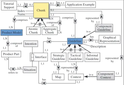
All chunks in the CREWS method base have the same structure. Figure 1 presents the meta model of the chunk. Every chunk comprises a product model and a process model. The product model represents the class of products obtained as outputs of the use of the chunk in specific applications. The process model represents the product development process and is described by the guideline. comprises1,1 1,N comprises 1,1 1,1 Guideline has Atomic Chunk composed of 1,N 1,1 Product Part 1,N 1,N 1,1 1,1 refers to Aggregate Chunk has 0,1 1,1 Strategic Guideline Tactical Guideline Informal Guideline Context Map 1,N 1,1 Interface Situation Intention represented by 1,1 1,1 has 1,1 1,1 Index Name Graphical Representation has 0,1 1,1 Component Guideline # # # represented by 1,1 0,1 Component Context represented by 1,1 Application Example Chunk Chunk composed of 1,N 0,N Product Model Description is-a is-a is-a Tutorial Support 1,1 has 0,1 is-a
Figure 1: The meta model of the chunk.
The guideline has an interface defined by the couple <situation, intention> which characterises the conditions of its applicability: the current situation which is the input to the chunk process (e.g. the goal) and the intention or goal that the chunk achieves (e.g. to elicit an alternative goal). The guideline interface represents also the interface of the chunk. The body of the guideline details how to apply the chunk to achieve the intention. It can be represented graphically and described informally according to the type of the guideline. There are three types of guidelines: strategic, tactical and informal.
The informal guideline does not provide any detailed process describing how to proceed to obtain the target product. Assumptions and informal explanation only are proposed in the guideline body.
The tactical guideline proposes a step-wise process to produce the corresponding product. It is represented by a tree of contexts following the NATURE process modelling formalism [Grosz 97]. The informal description is provided to facilitate the understanding and the application of the chunk. Figure 2 describes an example of the tactical guideline which is represented by a
3
choice context. This context proposes four different tactics to write scenarios describing how to achieve a given goal.
<(Goal), Write a scenario in free prose>
<(Goal), Write a scenario without guidelines> <(Goal), Write a scenario with style guidelines> <(Goal), Write a scenario with content guidelines> <(Goal), Write a scenario with style and content guidelines>
a1 a2
a3 a4
a1: The scenario author is not a scenario writing expert. A set of style and content guidelines are provided to support scenario writing.
a2: A set of style and content guidelines are provided to support scenario writing. a3: A set of style guidelines are provided to support scenario writing.
a4: The scenario author has to be a scenario writing expert.
Figure 2: The example of the tactical guideline.
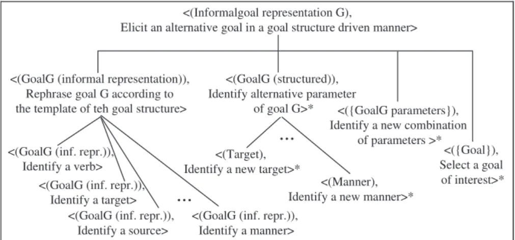
The contexts tree representing the tactical guideline may have some "leave" contexts which are represented in the method base as another chunks and are called "component chunks". Each leave context in Figure 2 is represented in the method base as another chunk. Figure 3 depicts the guideline of an another chunk from the CREWS method base which guideline is also represented by a contexts tree. Contrary to the previous one, all the leave contexts in this tactical guideline are simple guidelines and are not stored in the method base as other chunks. The guideline of this chunk describes the process allowing to elicit new goals which represents the alternatives to a given goal.
<(Informalgoal representation G),
Elicit an alternative goal in a goal structure driven manner>
<(GoalG (informal representation)), Rephrase goal G according to the template of teh goal structure>
<(GoalG (structured)), Identify alternative parameter
of goal G>* <({GoalG parameters}), Identify a new combination
of parameters >*
<({Goal}), Select a goal
of interest>* <(GoalG (inf. repr.)),
Identify a verb> <(GoalG (inf. repr.)),
Identify a target>
<(GoalG (inf. repr.)), Identify a manner>
...
<(Target), Identify a new target>*
<(Manner), Identify a new manner>* <(GoalG (inf. repr.)),
Identify a source>
...
Figure 3: The tactical guideline.
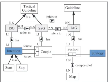
The strategic guideline provides a strategic view of the development process telling what can be achieved (which process intention) following which strategy. It is represented by a map and a set of guidelines. Figure 4 represents the structure of the strategic guideline. A map is a labelled directed graph in which the nodes are the intentions and the edges between intentions are the
strategies. The map permits to represent a process allowing several different ways to develop
the product. Each step providing several different manners to perform it is represented in the map by an intention to achieve and a set of strategies. Each strategy describes a different manner to achieve the intention. As the requirements engineer is using the map the process model is constructs dynamically.
Guideline Couple source target Section Strategy Intention Map
has has has
composed of 1,1 1,1 1,1 1,1 1,1 1,N 1,N 1,N Tactical Guideline refers to IAG refers to refers to SSG 0,N 0,N ISG 0,N 2,N 0,N 0,N Start Stop is-a is-a
Figure 4: The map structure
As shown in Figure 4, a map consists of a number of sections. Each of them is a triplet <source
intention, target intention, strategy> where the strategy defines the way to go from the source to the target intention. There are two distinct intentions, called Start and Stop, that represent the intentions to start navigating in the map and to stop doing so. Thus, it can be seen that there are several possible paths in the graph from Start to Stop.
Figure 5 depicts an example of the strategic guideline represented by a map. The interface of this guideline is <(Problem statement), Elicit goal / scenario couples following
CREWS-L'Ecritoire approach>. alternative discovery strategy composition discovery strategy goal structure driven
strategy Stop template driven strategy template driven strategy free prose strategy computer supported strategy manual strategy completeness strategy linguistic strategy Write a Scenario initial goal identification strategy Elicit a Goal Start refinement discovery strategy Conceptualise a Scenario
Figure 5: The example of the map
Three kinds of guidelines are used in the map to guide the requirements engineer in the construction of the intention driven process. The Intention Achievement Guideline (IAG) defines the way in which an intention can be achieved. For every section in the map there exists one IAG. The IAG supports the requirements engineer in the achievement of target intention according to the corresponding strategy. The IAG is a guideline which can be an informal guideline, a tactical guideline or another strategic guideline. Moreover, the IAG can be represented in the method base as an other chunk. For example, the tactical guideline presented in Figure 2 is the IAG associated to the section <Elicit a Goal, Write a scenario, free prose
5
strategy> of the map represented in Figure 5 and it is represented in the method base as an other chunk.
The Strategy Selection Guideline (SSG) determines the strategies connecting two intentions from which one is selected. For given couple of intentions <source intention, target intention> the SSG determines a set of possible strategies applicable to the source intention and allowing to achieve the target intention and guides the selection of a strategy thereby leading to the selection of the corresponding IAG. The SSG is always a tactical guideline and it can not be a chunk. For example in the map represented in Figure 5, there are two strategies, "template
driven" and "free prose", coming from the intention "Elicit a Goal" to the intention "Write a
Scenario". The SSG determining these strategies and providing the arguments to support the selection of the more appropriate strategy is presented in Figure 6.
SSG: <(Goal), Progress to (Write a Scenario)>
IAG: <(Goal),
Write a scenario with template driven strategy>
IAG: <(Goal), Write a scenario in free prose>
a1 a2
a1: The scenario author has to be a scenario writing expert, he/she has to fill a linguistic template. a2: The scenario author writs scenario in free prose. A set of style and content guidelines are provided to support scenario writing.
Figure 6: The example of the SSG
The Intention Selection Guideline (ISG) determines all succeeding intentions for a given one. For a given intention the ISG identifies the set of intentions that can be achieved in the next step and selects the corresponding set of either IAGs or SSGs. The former is valid when there is only one section between the source and the target intentions whereas the latter occurs when there are several sections between source and target intentions. The ISG is always a tactical guideline and it can not be a chunk. Figure 7 represents an example of the ISG which determines the intentions succeeding the intention "Elicit a goal" (map represented in Figure 5).
ISG: <(Goal), Progress from Elicit a Goal>
SSG: <(Goal), Progress to (Elicit a Goal)>
SSG: <(Goal), Progress to (Write a Scenario)>
a1 a2
a1: The process is centred towards the discovery of alternative goals. a2: The goal needs to be contretised through scenario authoring.
Figure 7: The example of the ISG
More details on the structure of the map are in [Rolland 99].
As presented before, every tactical and strategic guideline are recursively composed of other guidelines which can be represented in the method base as other chunks. Therefore, there are two types of chunks in the method base : atomic and aggregate ones. The aggregate chunks are composed of several atomic chunks. Each atomic chunk can participate in one or several aggregate chunks, each aggregate chunk can participate in other aggregates etc. Thus, the method base proposes chunks of different level of granularity. The method engineer can use the atomic chunks or some aggregations of them.
2.2 Meta-Knowledge Level
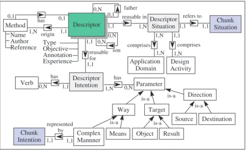
The knowledge on the reuse context of the chunk is captured in the chunk descriptor. Figure 8 represents the structure of the descriptor. The descriptor defines the design situation in which the chunk can be reused and the design intention which can be fulfilled by the chunk. The situation of the descriptor comprises two aspects: the application domains in which the chunk
can be applied and the design activities in which the scenario chunk is relevant. The intention of the chunk descriptor expresses how the scenario approach encapsulated in the chunk participates to the achievement of the design activity. Information Systems, Business Processes,
Socio-Technical Systems, Human Computer Interfaces are the examples of the application
domains in which the chunk represented in Figure 3 may be applied. The design activity supported by this chunk is Requirements Capture.
Type Objective Annotation Experience father son Descriptor Intention Method Name Author Reference Descriptor Descriptor origin 1,1 1,N 0,1 0,N 0,N 0,N 0,1 0,1 reusable in reusable for represented by 1,1 1,1 Chunk Intention comprises comprises Design Activity 1,N 1,N 1,N 1,1 1,1 1,N has 1,1 1,1 refers to Chunk Situation 1,1 1,1 Descriptor Situation Application Domain Parameter Verb has has 1,1 1,N 0,N 0,N Object Result Means Complex Mannner Source Destination Target Direction Way is-a is-a is-a is-a is-a
Figure 8: The structure of the descriptor.
The origin of the chunk, that is the name of the method in which the chunk has been identified, its author and the references to the literature, is also captured in its descriptor. If the overall method is presented in the method base as a chunk, the descriptors of its component chunks have the links to its descriptor. The descriptor specifies the type of the chunk (e.g. atomic or aggregate). If the chunk is an aggregate one its descriptor is linked to the descriptors of its components (to its sons). If the chunk is a component of one or several aggregate chunks, its descriptor is linked to the descriptors of the corresponding aggregates (its fathers).
The intention of the descriptor expresses how the chunk may participate to the achievement of the design activity in its application domain. For example, the descriptor intention of the chunk represented in Figure 3 is "Discover alternative system requirements by eliciting an alternative
goal in a goal structure driven manner". The structure of the intention is similar to the structure
of the chunk guideline intention. The intention of the descriptor is also specified by the intention verb, the target of this intention, but its manner is a complex manner and is recursively defined as an intention which is the intention of the chunk. For example in the intention described before, the verb is "Discover", the target is "alternative system
requirements" and the manner "by eliciting an alternative goal in a goal structure driven manner" is a recursive definition of the chunk intention in which the verb is "elicit" , the target
is "an alternative goal" and the manner is "in a goal structure driven manner". Now we will show how the CREWS method base has been realised.
3. Realisation of the CREWS Method Base
The CREWS method base is structured in two parts. One part deals with the knowledge necessary to the chunk selection and retrieval from the method base. This knowledge is represented using the SGML language. The second part deals with the representation of the reusable knowledge to the method base user. It is represented with HTLM documents. Thus, each chunk in the CREWS method base has two parts: the SGML part and the HTML part.
7
1. The SGML part contains the descriptor of the chunk. This part is used to retrieve the chunk from the method base by using an SGMLQL query.
2. The HTML part describes the body of the chunk: graphical representation and informal explanation of the guidelines, links to component chunks, reference to the product model etc, and also its context of reuse.
All chunks must have the same SGML structure presented below. We also propose a template for the HTML structure, but it can be adapted for each chunk.
3.1 SGML Part of the Method Base
The SGML (Standard Generalized Markup Language) [Goldfarb 90] is an international standard language to describe a document using a set of mark ups defined in a grammar. SGML documents are structured as trees. SGML's query language, SgmlQL [12] enables a user to query the SGML method base. Besides SgmlQL [Lemaitre 95] is available to query an SGML base of documents. We found the language adequate for representing the descriptors of our chunks.
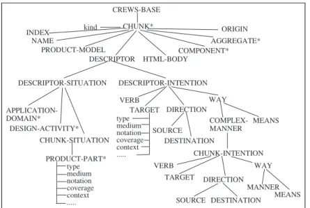
The SGML part of the chunk comprises the information necessary for the chunk retrieval. This information is represented in the chunk descriptor. SGML uses the notion of composition to relate its elements. The SGML structure of the CREWS method base is the tree presented in Figure 9. The root of the CREWS method base is the element CREWS-BASE which represents a collection of CHUNKs. The element CHUNK is itself characterised by the attribute kind and the tags: INDEX, PRODUCT-MODEL, DESCRIPTOR, HTML-BODY, COMPONENT, AGGREGATE and ORIGIN. A chunk is considered as atomic when it reaches an intention which cannot be decomposed into more detailed intentions, on the contrary it is called
composed. The INDEX is an identification of the chunk. The PRODUCT-MODEL contains the name of the corresponding product model. The DESCRIPTOR is composed of DESCRIPTOR-SITUATION and DESCRIPTOR-INTENTION.
CREWS-BASE CHUNK* NAME PRODUCT-MODEL DESCRIPTOR HTML-BODY COMPONENT* AGGREGATE* DESCRIPTOR-SITUATION DESCRIPTOR-INTENTION APPLICATION-DOMAIN* DESIGN-ACTIVITY* CHUNK-SITUATION PRODUCT-PART* VERB TARGET DIRECTION SOURCE DESTINATION WAY COMPLEX-MANNER MEANS CHUNK-INTENTION VERB TARGET DIRECTION SOURCE DESTINATION WAY MANNER MEANS ORIGIN kind type medium notation coverage context ... type medium notation coverage context ... INDEX
Figure 9: The structure of SGML part of the CREWS method base.
As presented in Figure 9, the DESCRIPTOR-SITUATION has three parts: APPLICATION-DOMAIN, DESIGN-ACTIVITY and CHUNK-SITUATION. Every chunk can be applied in one or several application domains and support one or several design activities. The CHUNK-SITUATION precise what are the required PRODUCT-PARTs allowing to apply the chunk. If the type of the required product is "scenario based", this product must be characterised by providing values to the classification attributes. These scenario classification attributes are
defined in the scenario classification framework [Rolland 98b]. They permits to specify what is the required scenario medium (text, table, graphic, image, etc.), notation (informal, formal, semi-formal), interactivity (None, hypertext-like, advanced), animation (True, False), coverage (functional, intentional, non-functional) etc. The DESCRIPTOR-INTENTION is decomposed into a VERB and its parameters TARGET, DIRECTION and WAY according to the goal template (see [Prat 97]). The parameter TARGET is mandatory in the intention description, whereas the DIRECTION (SOURCE and DESTINATION) is optional. The COMPLEX-MANNER of the parameter WAY is also mandatory because it describes recursively the intention of the corresponding chunk whereas the MEANS is optional. For example, given the chunk intention "Write scenario in free prose", the intention of the corresponding descriptor is
"Describe system requirements with write scenario in free prose strategy ".
The HTML-BODY contains the name of the corresponding HTML file. The COMPONENT and AGGREGATE tags comprise the indexes of the component chunks and the aggregate chunks respectively. The ORIGIN permits to identify the chunk which represents the overall method in which the corresponding chunk take part.
Figure 10 presents an example of the SGML part of the chunk presented in Figure 3.
<CHUNK kind="atomic"> <INDEX>chunk14</INDEX>
<NAME>Elicit a goal in a goal structure driven manner</NAME> <PRODUCT-MODEL>CREWS-L' Ecritoite</PRODUCT-MODEL> <DESCRIPTOR>< DESCRIPTOR-SITUATION>
<APPLICATION-DOMAIN>Information Systems</APPLICATION-DOMAIN> <APPLICATION-DOMAIN>Business Processes</APPLICATION-DOMAIN> <APPLICATION-DOMAIN>Socio-Technical Systems</APPLICATION-DOMAIN> <APPLICATION-DOMAIN>Human Computer Interfaces</APPLICATION-DOMAIN> <DESIGN-ACTIVITY>Requirements Capture</DESIGN-ACTIVITY>
<CHUNK-SITUATION><PRODUCT-PART type="Non scenario based">Goal</PRODUCT-PART> </CHUNK-SITUATION></DESCRIPTOR-SITUATION>
<DESCRIPTOR-INTENTION>
<VERB>Discover</VERB><TARGET>System requirements</TARGET> <COMPLEX-MANNER> <VERB>Elicit</VERB><TARGET>Goal</TARGET> <MANNER> Goal structure driven </MANNER>
</COMPLEX-MANNER></DESCRIPTOR-INTENTION> <HTML-BODY>chunk14_index.html</HTML-BODY> <AGGREGATE>chunk19_index.html</AGGREGATE>
<ORIGIN>CREWS-L' Ecritoire</ORIGIN></DESCRIPTOR></CHUNK>
Figure 10: The example of the SGML part of the chunk.
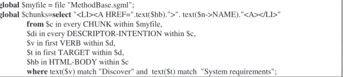
We use the SGMLQL query language to retrieve the chunks from the method base. The query represented in Figure 11 select the chunks which support the discovering of the system requirements. The search is based on the descriptor intention verb "Discover" and target
"System requirements". The result of this query is a list of selected chunk names linked to the
9
global $myfile = file "MethodBase.sgml";
global $chunks=select "<LI><A HREF=".text($hb).">". text($n->NAME)."<A></LI>" from $c in every CHUNK within $myfile,
$di in every DESCRIPTOR-INTENTION within $c, $v in first VERB within $d,
$t in first TARGET within $d, $hb in HTML-BODY within $c
where text($v) match "Discover" and text($t) match "System requirements";
Figure 11: The example of the query.
3.2 HTML part of the chunk
The HTML part of the chunk represents both the body of the chunk and the context of its applicability. Every chunk is represented by one core HTLH document and may have several links to other HTLH documents. The core document of each chunk has the same structure and comprises the following sections :
• Every chunk has a name which corresponds to the intention of the chunk described in the informal manner. "Elicit an alternative goal in a goal structure driven manner" is an example of the chunk name. It also corresponds to the intention of this chunk.
• The objective of the chunk is provides in the corresponding section.
• The section Situation tells us which are the product parts necessary to start the application of the chunk. This section defines the link to the HTLH document describing these product parts in detail. The informal description can be proposed to overview the product parts to avoid the navigation to other documents. Moreover, the links to the glossary of the method base permits to consult their definitions and to find possible synonyms.
• The section Intention specifies what is the intention of the chunk. Because the intention of the chunk has a predefined structure, each of its component is explained. The link is leaded to the verb definition and its synonyms in the glossary of the method base. Another link permits to access the document describing the target product. The manner and means to satisfy the intention are also made more explicit.
• The Graphical representation section represents the picture of the chunk process.
• The section Description follows the graphical representation and informally explains the process of the chunk.
• An Example of the chunk application may be provided to facilitate the comprehensibility of the chunk.
• The type of the chunk determines if it is an atomic chunk or an aggregate one. If the chunk is an aggregate one its HTLH page has a section named Components. This section defines the links to the HTLH documents of the corresponding component chunks and permits to access these chunks. If the chunk is a component of one or several aggregates the section
Aggregates defines the links to the HTLH documents of the corresponding chunks.
• The section Origin comprises the name of the method or the approach in which the chunk has been identified, the references in the literature, the names of the chunk authors. If the overall method is also presented in the method base as a chunk the section Origin contains the link to its HTLH file.
• The section Tutorial support may contain the presentation of the tool supporting the chunk, the slides, the demos and etc.
• The Reuse context section represents the context in which the chunk can be reused : the application domains in which it can be applied, the design activities which can be supported by the chunk, the intention of the chunk. Some annotations and experience of the application of the chunk may be provided in this section.
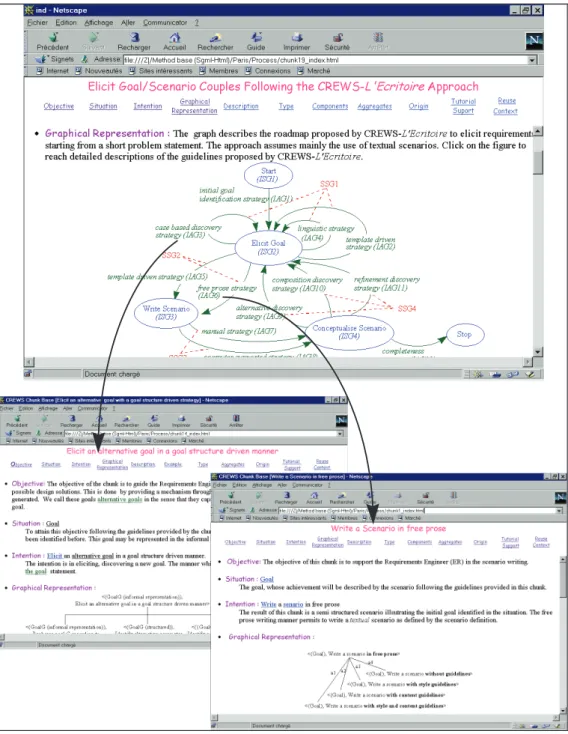
Figure 12 represents the HTLH documents of three CREWS method base chunks. The chunk represented in the top window is an aggregate one. We can access the components of this chunk represented in the two other windows by clicking on the map elements or by clicking on the component names listed in the section "Components".
11
4. Conclusion
In this paper we propose an approach for supporting the reuse of scenario based chunks made available in the CREWS method base. The proposed approach advocates a modular representation of scenario chunks and an intentional description of their reuse context. The former results is cohesive chunks which are applicable in specific situations for specific purposes whereas the latter provides contextual information identifying in which specific design situations for which specific design intentions the chunks are reusable. The paper also reports on the implementation of a scenario method base in SGML and HTLH and illustrates it through the examples.
Future work shall concentrate on developing guidelines to integrate scenario method chunks in existing methods. Besides, in order to support the process for retrieving chunks matching specific requirements we are developing a set of SgmlQL macro-queries. At the moment, the CREWS method base contains only the chunks defined by CREWS project partners. In the future, we shall add in our base the chunks coming from different scenario based methods as OOSE [Jacobson 92] and approaches as [Holbrook 90], [Hsia 94], [Lalioti 95], [Kyng 95], [Carroll 95] etc.
5. References
[Brinkkemper 98] S. Brinkkemper, M. Saeki, F. Harmsen, Assembly Techniques for Method Engineering. Proceedings of the 10th
Conference on Advanced Information Systems Engineering, CAiSE’98. Pisa Italy, 8-12 June, 1998.
[Carroll 95] J. M. Caroll, "The Scenario Perspective on System Development", in Scenario-Based Design: Envisioning Work and Technology in System Development, Ed J.M. Carroll, 1995.
[Dubois 98] E. Dubois, P. Heymans, Scenario-Based Techniques for supporting the Elaboration and the Validation of Formal Requirements, Submitted to RE Journal, 1998.
[Goldfarb 90] : C. F. Goldfarb, « The SGML Handbook », Oxford Clarendon Press, 1990.
[Grosz 97] G. Grosz, C. Rolland, S. Schwer, C. Souveyet, V. Plihon, S. Si-Said, C. Ben Achour, C. Gnaho, Modelling and Engineering the Requirements Engineering Process : an overview of the NATURE approach. Requirements Engineering Journal 2, pp. 115-131, 1997.
[Harmsen 94] F. Harmsen, S. Brinkkemper, H. Oei, Situational Method Engineering for Information System Projects. In Olle T. W. and A. A. Verrijn Stuart (Eds.), Mathods and Associated Tools for the Information Systems Life Cycle, Proceedings of the IFIP WG8.1 Working Conference CRIS' 94, pp. 169-194, North-Holland, Amsterdam, 1994.
[Harmsen 97] F. Harmsen, Situational Method Engineering. Moret Ernst & Young, 1997.
[Haumer 98] P. Haumer, K. Pohl, K. Weidenhaupt, Requirements Elicitation and Validation with real world scenes. IEEE Transactions on Software Engineering, Vol. 24, N°. 12, Special Issue on Scenario Management, December. 1998.
[Holbrook 90] C. H. Holbrrok_III, "A Scenario-Based Methodology for Conducting Requirement Elicitation", ACM SIGSOFT Software Engineering Notes, 15 (1), pp.95-104, 1990.
[Hsia 94] P. Hsia, J. Samuel, J. Gao, D. Kung, Y. Toyoshima, C. Chen, "Formal Approach to Scenario Analysis", IEEE Software, pp. 33-41, 1994.
[Kyng 95] M. Kyng, "Creating Contexts for Design", In John M. Carroll, editor, Scenario-Based Design: Envisioning Work and Technology in System Development, pages 85-107. John Wiley and Sons,1995.
[Lalioti 95] V. Lalioti and B. Theodoulidis, "Use of Scenarios for Validation of Conceptual Specification", Proceedings of the Sixth Workshop on the Next Generation of CASE Tools, Jyvaskyla, Finland, June 1995.
[Lemaitre 95] : J. Lemaitre, E. Murisasco, M. Rolbert, SgmlQL, « Un langage d'interrogation de documents SGML », Proceedings of the 11th conference on Advanced DataBases, August 1995, Nancy, France.
[Plihon 98] V. Plihon, J. Ralyté, A. Benjamen, N.A.M. Maiden, A. Sutcliffe, E. Dubois, P. Heymans, A reuse-oriented approach for the construction of scenario based methods. Proceedings of the International Software Process Association’s 5th International Conference on Software Process (ICSP’98), Chicago, Illinois, USA, 14-17 June 1998.
[Prat 97] N. Prat, Goal formalisation and classification for requirements engineering. Proceedings of the Third International Workshop on Requirements Engineering: Foundations of Software Quality REFSQ’97, Barcelona, pp. 145 -156, June 1997.
[Rolland 96] C. Rolland, N. Prakash, A proposal for Context-Specific Method Engineering, IFIP TC8 Working Conference on Method Engineering, Atlanta, Gerorgie, USA, 1996.
[Rolland 97] C. Rolland, C. Ben Achour, Guiding the construction of textual use case specifications. Data & Knowledge Engineering Journal Vol. 25 N° 1, pp. 125-160, (ed. P. Chen, R.P. van de Riet) North Holland, Elsevier Science Publishers. March 1997.
[Rolland 98a] C. Rolland, C. Souveyet, C. Ben Achour, Guiding Goal Modelling Using Scenarios. IEEE Transactions on Software Engineering, special issue on Scenario Management, 1998.
[Rolland 98b] C. Rolland, C. Ben Achour, C. Cauvet, J. Ralyté, A. Sutcliffe, N.A.M. Maiden, M. Jarke, P. Haumer, K. Pohl, Dubois, P. Heymans, A proposal for a scenario classification framework. Requirements Engineering Journal Vol 3, No 1, Springer Verlag, pp.23-47, 1998.
[Rolland 99] C. Rolland, N. Prakash, A. Benjamen, A multi-model view of process modelling. To appear in the RE journal, 1999.
[Sutcliffe 98] A. G. Sutcliffe, Scenario-based Requirements Analysis. Requirements Engineering Journal, Vol (3) N° 1, (ed. P. Loucopoulos, C. Potts), Springer Verlag. 1998.