HAL Id: hal-01617765
https://hal.archives-ouvertes.fr/hal-01617765
Submitted on 17 Oct 2017HAL is a multi-disciplinary open access
archive for the deposit and dissemination of sci-entific research documents, whether they are pub-lished or not. The documents may come from teaching and research institutions in France or abroad, or from public or private research centers.
L’archive ouverte pluridisciplinaire HAL, est destinée au dépôt et à la diffusion de documents scientifiques de niveau recherche, publiés ou non, émanant des établissements d’enseignement et de recherche français ou étrangers, des laboratoires publics ou privés.
Nanoscale multilayered and porous carbide interphases
prepared by pressure-pulsed reactive chemical vapor
deposition for ceramic matrix composites
Sylvain Jacques, I. Jouanny, O. Ledain, L. Maillé, P. Weisbecker
To cite this version:
Sylvain Jacques, I. Jouanny, O. Ledain, L. Maillé, P. Weisbecker. Nanoscale multilayered and porous carbide interphases prepared by pressure-pulsed reactive chemical vapor deposition for ceramic matrix composites. Applied Surface Science, Elsevier, 2013, 275, pp.102 - 109. �10.1016/j.apsusc.2013.01.100�. �hal-01617765�
Nanoscale multilayered and porous carbide interphases prepared by pressure-Pulsed Reactive Chemical Vapor Deposition for Ceramic Matrix Composites
S. Jacques, I. Jouanny, O. Ledain, L. Maillé, P. Weisbecker
LCTS, University of Bordeaux 1, CNRS, Herakles-Safran, CEA, 3 allee de la Boetie, F-33600 Pessac, France
Abstract
In Ceramic Matrix Composites (CMCs) reinforced by continuous fibers, a good toughness is achieved by adding a thin film called "interphase" between the fiber and the brittle matrix, which acts as a mechanical fuse by deflecting the matrix cracks. Pyrocarbon (PyC), with or without carbide sub-layers, is typically the material of choice to fulfill this role. The aim of this work was to study PyC-free nanoscale multilayered carbide coatings as interphases for CMCs.
Nanoscale multilayered (SiC-TiC)n interphases were deposited by pressure-Pulsed Chemical
Vapor Deposition (P-CVD) on single filament Hi-Nicalon fibers and embedded in a SiC matrix sheath. The thicknesses of the carbide interphase sub-layers could be made as low as a few nanometers as evidenced by scanning and transmission electron microscopy. By using the P-ReactiveCVD method (P-RCVD), in which the TiC growth involves consumption of SiC, it was not only possible to obtain multilayered (SiC-TiC)n films but also TiC films with a porous
multilayered microstructure as a result of the Kirkendall effect. The porosity in the TiC sequences was found to be enhanced when some PyC was added to SiC prior to total RCVD consumption. Because the porosity volume fraction was still not high enough, the role of mechanical fuse of the interphases could not be evidenced from the tensile curves, which remained fully linear even when chemical attack of the fiber surface was avoided.
Keywords
1. Introduction
In Ceramic Matrix Composites (CMCs) reinforced by continuous fibers, the fiber/matrix interface must be controlled for obtaining non-brittle and high performance materials [1]. This is achieved through a fiber coating called 'interphase' that acts as a mechanical fuse by deflecting the cracks created in the brittle matrix before they reach the fibers [2] [3]. In CMCs developed for applications in aeronautic engines or energy production like SiC/SiC in which both the matrix and the fiber reinforcement are SiC-based, the interphase material of choice is the pyrocarbon (PyC), but its poor oxidation resistance causes embrittlement of these composites when used at high temperature in oxidizing atmosphere [4] [5]. PyC can be replaced by boron nitride, another material with a layered crystal structure, but BN is poorly compatible with nuclear applications and its water sensitivity leads to CMC degradation in moist environments [6] [7]. (ZrO2)n multiple zirconium dioxide interphases in which weak
interlayer cohesion originates from porosity and disordered bonds between adjacent ZrO2 layers showed promising results [8]. However, zirconia is subject to martensitic transformation at high temperature [9], which may affect the CMC behavior under thermal cycling. Another solution consists in replacing part of the PyC interphase by carbide in order to reduce to a minimum the presence of the sensitive free carbon. Hence, pseudo 'porous' SiC interphases (a mixture of carbon and SiC) and now more common (PyC-carbide)n
multilayered interphases made up of a stack of n PyC and carbide sub-layers have exhibited interesting behaviors in severe environments like neutron irradiation at high temperature [10] [6]. However, even though the irradiation does not dramatically degrade the tensile mechanical performance of the SiC/SiC composites with PyC-containing interphases, the irradiation-induced dimensional change of carbon causes a fiber-matrix bonding weakening under certain conditions [11] [12] that may have a detrimental effect on the composite resistance in long term applications. Thus, the use of pure carbide interphases, i.e. without the drawbacks of pyrocarbon, boron nitride or oxide materials, would allow CMC properties to be maintained in severe conditions. The problem of carbide brittleness and the achievement of a mechanical fuse could be overcome by laminating the carbide material itself at the nanometer scale.
A way to process (PyC-carbide)n nanoscale multilayered coatings with PyC sub-layers as
thin as a few nanometers on fibers in preforms is the use of pressure-Pulsed Chemical Vapor Deposition or Infiltration (P-CVD/CVI), a method adapted from CVD [3] [13] [14]. Another way is the use of pressure-Pulsed Reactive CVD or CVI (P-RCVD/RCVI) adapted from the RCVD method in which a part of the elements of the deposited coating comes from the substrate [15] [16]. The basic RCVD method was successfully applied by Bouix et
thin various carbide films for high temperature oxidation protection. If P-RCVD has demonstrated its interest in the design of (PyC-TiC)n interphases, a first attempt to get a
good mechanical fuse only made of pure carbide by total removing of PyC during the carbide growth was unsuccessful [22].
The aim of the present paper was to obtain and study new nanoscale multilayered coatings by P-(R)CVD, but here by replacing the classical PyC sub-layers by SiC sub-layers in order to prepare PyC-free (SiC-TiC)n interphases for CMCs. The alternation of carbide sub-layers
with different microstructures and coefficients of thermal expansion should induce shear stresses at the interfaces that may be able to deflect the matrix cracks. Furthermore, the use of P-RCVD for the growth of the TiC sub-layers also allowed the study of the total consumption of the SiC sub-layers and its result on the composite behavior with pure TiC multilayered interphases.
2. Experimental procedure
2.1. Synthesis of coatings
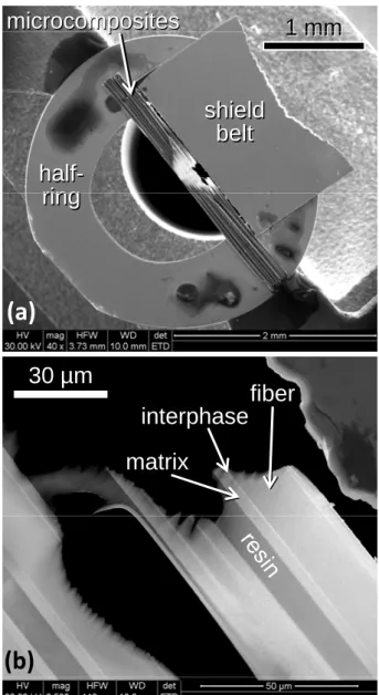
The experimental study was carried out by using microcomposites. A microcomposite is a model composite consisting of one single fiber coated with the interphase and embedded in the matrix (Fig. 1). It represents the elementary cell of the composite and can be easily prepared by CVD methods [23]. It allows the interphase behavior to be studied.
Carbide multilayered coatings were deposited on Hi-Nicalon single fibers (~14 µm in diameter, from Nippon Carbon, Japan) by two CVD methods: P-CVD and P-RCVD at a temperature close to 1373 K in the same CVD device as Jouanny et al. [24]. Pressure pulses were obtained within the chamber by opening and closing pneumatic valves at regular intervals through an automatic controller. Both methods used successive pulses composed of a brief injection stage of gases into the reactor during 0.5 s, a reaction stage with the gases in the closed reactor at a low pulse pressure ranging from 2 to 4 kPa during 4 s and an evacuation stage of the gases by the pumping system (3 s). So the total time of each pulse cycle was 7.5 seconds.
SiC sub-layers were deposited by P-CVD from a H2/MTS gaseous mixture (MTS: CH3Cl3Si) with a pulse pressure equal to 2 kPa. TiC sub-layers were synthesized either by CVD or P-RCVD with a pulse pressure equal to 3.5 kPa. In the CVD method, the gases were H2/CH4/TiCl4 supplying both carbon and titanium elements to the TiC coating. The dilution ratio of TiCl4 in H2 was 13 and the dilution ratio of CH4 in H2 was 10. In the RCVD method, the gases were H2/TiCl4. Pure TiC could be obtained with a low enough dilution ratio of TiCl4
in H2 (13-15), the carbon coming from the previously deposited SiC sub-layer [25] [26]. Therefore the TiC sub-layers were synthesized by consumption of the SiC sub-layers, the silicon being evacuated in the gaseous phase in the form of by-product species.
The multilayered coatings and interphases made of silicon and titanium carbides were named (SiC-TiC)n where n was the total number of carbide dual-layers within the film.
Each single phase sub-layer was prepared with a series of gas pulses. Each (SiC-TiC) dual-layer was prepared with a sequence of two series composed of a number s and a number t of gas pulses used for the SiC and the TiC sub-layer deposition respectively. The notation (ss-tt)n referred to as the pulse series sequences used for the corresponding multilayered
coating processing.
For a given number s of H2/MTS pulses, when the number t of H2/TiCl4 pulses was high enough to totally consume the SiC sub-layers previously deposited by CVD through the P-RCVD growth of the TiC sub-layers, the resulting pure titanium carbide coating was represented by the notation (ø-TiC)n where ø corresponds to a lost pure SiC sub-layer.
In some cases, one pure propane pulse (3.5 kPa) was added to the H2/MTS pulse series in order to add some pyrocarbon (PyC) in the SiC sub-layer before its total RCVD consumption. The notation (ss/1p/ss-tt)n referred to as such pulse series sequences in which the propane
pulse was interposed between two series of s H2/MTS pulses before each series of t H2/TiCl4 pulses. The resulting pure titanium carbide coating was represented by the simplified notation (Ø-TiC)n where Ø corresponds to the lost SiC and PyC.
The microcomposites were prepared by deposition of the interphase (with a thickness ranging from 0.4 to 1.0 µm) on Hi-Nicalon single fibers, followed by the P-CVD growth of the SiC matrix (with a thickness ranging from 0.5 to 3.3 µm).
2.2. Characterization
The microstructural study was performed by transmission electron microscopy (TEM-Philips CM30 microscope) using a LaB6 source operating at 300 kV. Because the region of interest was the (SiC-TiC)n multilayered coating deposited on the fiber, a method to prepare TEM
thin-foil samples in the longitudinal fiber direction was required with minimum irradiation damage. The Argon Ion Slicing (JEOL Ion Slicer EM-09100IS) method was used. This method showed a lower irradiation damage for SiC/SiC composites than the standard methods (FIB and argon ion milling) [27]. At least ten coated fibers were embedded in an epoxy resin then stuck on a copper half-ring with a 10 µm thick piece of shield belt (Fig. 2). Then, the preparation was thinned by Argon Ion Slicing following the method indicated by [27]. It is worth mentioning that the redeposition phenomenon was not observed in the TEM samples.
Coatings were observed by scanning electron microscopy (SEM-Quanta 400 FEG V2 microscope) using backscattered electron (BSE) and secondary electron (SE) detectors, with an accelerating voltage fixed at 15 kV. To study the growth rate of TiC and SiC, the layer thicknesses were measured from BSE-SEM images. Composition line profiles were performed through the section of the coatings from TEM thin-foil samples in this scanning electron microscope by Energy Dispersive X-ray Spectroscopy (EDS) with an accelerating voltage fixed at 30 kV. The very low thin-foil sample thickness (< 100 nm) allowed the pear-shaped interaction volume to be avoided and so the EDS spatial resolution to be enhanced. Morphology observations were also carried out in a second SEM microscope (Hitachi S4500 FEG) with a SE detector and an accelerating voltage fixed at 3 or 5 kV.
Chemical analyses of coatings were also carried out by Auger electron spectroscopy (AES-VG Microlab 310F spectrometer) with simultaneous Ar+ etching in order to obtain the concentration depth profiles of carbon, titanium, oxygen and silicon. The Auger spectra were obtained with an electron beam energy of 10 kV and a beam current of 5 nA and focused to a spot on substrate (about 1 µm). For the etching, the voltage and current of the ion beam were kept at 4.0 kV and 0.5 nA, respectively. The sputtering rate was estimated at ~1 Å/s.
A specific table-model testing machine was used to perform tensile tests at room temperature. Coated fiber failure stresses were obtained from 20 tests per batch with a gauge length of 25 mm according to a single fiber test procedure [28]. The specimen (coated fiber or microcomposite) was mounted on a paper frame; the paper frame was aligned in the grips and then the frame sides were cut. The specimen was loaded up to failure. The stresses at failure were determined by dividing the load at failure by the section of the specimen. For each batch of coated fibers or microcomposites, the given value was an arithmetic mean obtained from the 20 tested specimens.
3. Results and discussion
3.1. Growth rate of SiC and TiC sub-layers
3.1.1. P-CVD SiC and TiC growth
SiC/TiC multilayered coatings were synthesized by P-CVD with H2/MTS and H2/CH4/TiCl4 pulse numbers varying from 3 to 25. The thicknesses of the carbide sub-layers were
measured from BSE-SEM observations where the observed SiC layers are dark whereas the TiC layers are bright, as shown in Fig. 3.
The SiC and TiC layer thicknesses range from 20 to 160 nm and from 10 to 80 nm respectively and were both proportional to the pulse numbers with virtually no initiation stage. In P-CVD, the steady-state conditions were reached from the first pulses. The growth rates were about 7 nm/pulse and 3 nm/pulse for SiC and TiC respectively.
3.1.2. P-RCVD TiC growth
In the P-RCVD method (i.e. without methane), the TiC growth rate depended on the thickness because of the occurrence of an initiation stage where the growth was delayed and difficult to control. For a thickness lower than 50 nm, the growth rate was irregular and lower than 1 nm/pulse. Figure 4 shows that from 50 nm thick and ~120 pulses onwards, the thickness increases linearly with the number of pulses t and the growth rate never exceeds 1.5 nm/pulse, which remains twice as low as by P-CVD with CH4. This feature was attributed to the way how carbon atoms were brought to the growing TiC coating: through solid-state diffusion from SiC in RCVD, which was more limiting than the direct supply from gaseous methane simultaneously with TiCl4 in CVD. Despite this solid-state diffusion limitation but owing to the sub-micrometer thickness range of the present P-RCVD study, no growth slowdown was observed as in classical RCVD for coatings thicker than 1 µm [25].
From SEM observations of graded multilayered coatings (Fig. 4a), knowing the constant SiC growth rate and so the initial SiC thicknesses at each sequence, it was possible to deduce the SiC thickness consumed during the P-RCVD growth of each next TiC layer. Figure 4b shows that the SiC consumption rate is constant and equal to 0.8 nm/pulse from the early stages. As a result by comparison with TiC growth rate, the volume conversion ratio from SiC to TiC increased from 0.5 (±0.1) with t = 120 to 1.2 (±0.2) with t = 240. Assuming that one mole of SiC gives one mole of stoichiometric TiC by RCVD and taking into account the similar molar volumes of both carbides, the theoretical volume conversion ratio should be close to one. If the produced titanium carbide is substoichiometric, the theoretical volume conversion ratio should be greater than one. The experimental value smaller than 1.0 found for low t means that the lost SiC is not totally involved in the TiC production. A part of the SiC loss could be assigned to the carbon loss in the form of hydrocarbon additionally to the loss of silicon evacuated in the form of silicon chlorides in the gaseous phase [26]. Only a small part of the carbon of the lost SiC was involved in TiC growth during its initial stage.
3.2. (SiC-TiC)n interphases
3.2.1. Interphases deposited by P-CVD
Four fiber (SiC-TiC)n multilayered coatings were prepared by P-CVD without a matrix
according to (ss-tt)n pulse series sequences with s = 1 or 2, t = 7 or 15 and n ranging from 7
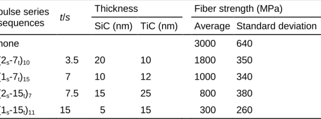
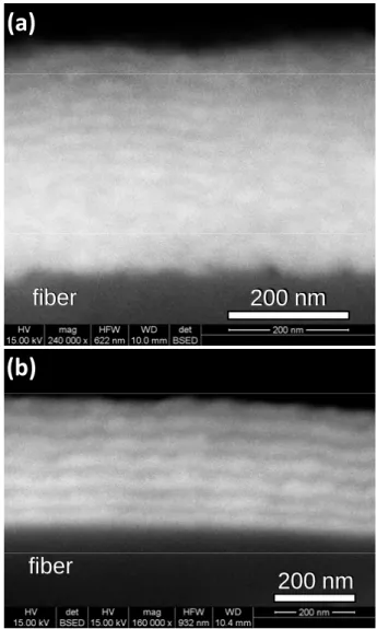
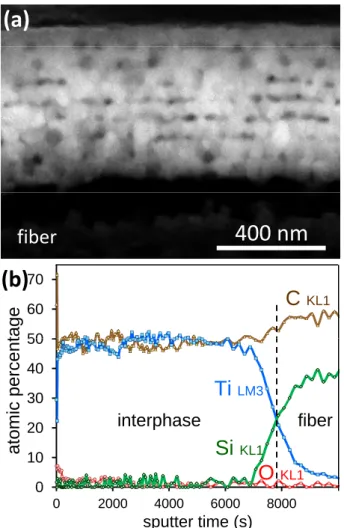
to 15 (Tab. 1). It was possible to obtain very thin continuous carbide sub-layers with thicknesses as low as a few nanometers. While the different very thin carbide sub-layers become hardly distinguishable by SEM when s and t are small (Fig. 5a), the series of silicon and titanium carbides are clearly evidenced with continuous sub-layers for larger numbers of pulses (Fig. 5b). The EDS depth profile ripples, where each maximum of the Ti intensity curve corresponds to a minimum of the Si intensity curve and conversely, account for the multilayered structure (Fig. 6). But it may also be noticed that SiC sub-layer thickness depended not only on s but also on t, the pulse number of (H2/TiCl4) used for TiC sub-layer growth: for a given value of s, the SiC sub-layers were thinner with t = 15 than with t = 7 (Tab. 1). This result suggests that some SiC consumption and so some "RCVD-like" mechanism occurred despite the use of methane as the main carbon source.
The stress at failure decreased with the presence of a (SiC-TiC)n multilayered coating
especially when the t/s pulse ratio increased in the coating (Tab. 1). The TEM brightfield image of the (SiC-TiC)7 multilayered interphase prepared with (2s-15t)7 pulse sequences shows the seven (SiC-TiC) dual-layers, each of them being continuous and parallel to the fiber surface (Fig. 7). Each TiC sub-layer is made of contiguous grains which are equivalent in size to the thickness of the sub-layer. The enlarged section of the interfacial area also shows that the fiber surface was damaged by chlorinated gases or by diffusion of titanium species at high temperature resulting in a 10 nm thick TiC interlayer. This observation confirms that for low thicknesses and in our experimental conditions (chemical composition of gases, temperature and pressure), the CVD method is not totally separated from the P-RCVD method. As in the case of the study of Jouanny et al., this local chemical attack by titanium containing-species results in the presence of brittle TiC grains and so flaws that create notch effects at the surface of the fiber that are responsible for the mechanical properties drop of the coated fibers [24]. The mechanical properties gradually decreases when the number of pulses t and so the presence of TiC at the fiber surface increases. In the present study with the (SiC-TiC)n multilayered coatings, this phenomenon is further aggravated by the decrease of the number of pulses s because it reduces the thickness of the initial protective SiC interlayer which gradually less prevents the formation of TiC grains at the surface of the fiber (Fig. 7). The discrepancy with Baklanova et al. who reported that the strength of the carbon fibers coated with TiC grown by RCVD were preserved and even
slightly increased may arise not only from the different fiber nature but also from the use of carbon-containing gas (CF4) meaning that the used CVD method could be not totally 'reactive', carbon atoms being able to be also provided by the gas [21]. Conversely, Baklanova et al. reported that in the course of RCVD HfC deposition, the carbon fiber was gradually becoming more brittle in comparison with the initial fiber [20]. These different results highlighted the delicate control of the carbon source during the carburization surface of carbon-containing substrates and so the difficulty of ensuring their integrity.
3.2.2. Interphases deposited by P-RCVD
Fig. 8 shows a (SiC-TiC)7 multilayered interphase deposited by P-RCVD (without CH4) with (8s-30t)7 pulse sequences and then embedded in a SiC matrix. The carbides sub-layers are poly-crystalline, fully continuous and regular around the fiber. Each type of carbide sub-layer can be located on SEM EDS X-ray elemental maps and the multilayered structure is also evidenced by the EDS depth profiles (Fig. 9). However, only six TiC sub-layers are observed in the profile. The two first TiC sub-layers appear mixed up because of a local SiC sub-layer initially thinner than the others or because of a local enhancement of SiC loss. Despite that, no fiber surface attack was clearly observed by TEM, likely due to a first SiC sub-layer initially just thick enough to protect the fiber from RCVD reaction.
Thanks to this protection, the average tensile stress at failure of the microcomposites with this (SiC-TiC)7 multilayered interphase was as high as 1000 MPa, but proportional limit and failure were identical, only a linear elastic behavior without a damageable behavior was observed. Therefore, it can be concluded that the (SiC-TiC)n interphase itself did not act as a
mechanical fuse.
3.3. Porous TiC interphases and coatings
3.3.1. (ø-TiC)n interphases
(ø-TiC)8 interphases were deposited by P-RCVD without a matrix with (10s-50t)8 pulse sequences (Fig. 10). The absence of silicon outside the fiber in the AES depth concentration profiles of the coatings shows that each initial SiC sub-layer initially deposited with the ten H2/MTS pulses was then totally consumed by the fifty H2/TiCl4 pulses (Fig. 10b). Nevertheless, the coating still exhibits a multilayer-like microstructure where the eight TiC sub-layers with a thickness of about 70 nm can be observed by SEM (Fig. 10a). Figure 11
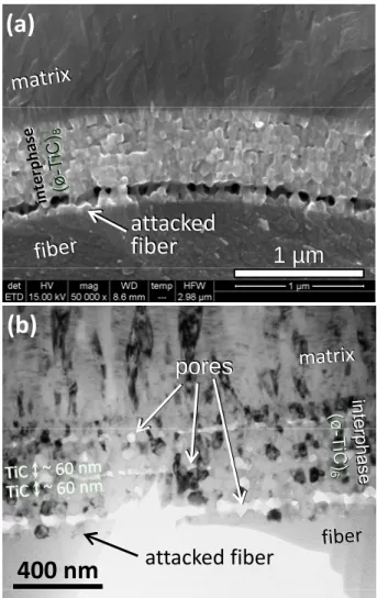
shows similar interphases prepared with (8s-40t) pulse sequences where the presence of lined up pores is clearly evidenced. These pores were produced by the Kirkendall effect based on nonreciprocal mutual solid-state diffusion process through an interface of two materials, i.e. carbon versus titanium atom diffusion between SiC and TiC. Nowadays, such effect is exploited as a new fabrication route to designed hollow nano-objects [29]. In the present study, these pores were created in the TiC layers when the intermediate SiC layer was vanishing. As long as some SiC remained at the surface of the previous TiC sub-layer, the growth of the next TiC sub-layer occurred without pore formation. Some formation of pores in TiC grown by P-RCVD has already been reported when the initial substrate sub-layers are made of pure PyC [22]. The transport rate of carbon atoms through the titanium carbide layer is much faster than the one of titanium atoms in the opposite direction, causing the Kirkendall effect. But in that former case with only pure PyC as initial carbon precursor, the pores were few. In the present study with SiC as initial substrate by comparison with the previous one with PyC, the formed pores in TiC are noticeably more numerous. The precise mechanism of the formation of pores is not clearly established so far but the presence of silicon initially combined with carbon and then evacuated in the gaseous phase appeared to play an important role in the obvious porosity formation.
The pore formation was even more pronounced near the surface of the Hi-Nicalon fiber where it occurred simultaneously with the attack of the fiber. The damaging of the fiber reinforcement led to an average tensile stress at failure of the microcomposites of only 700 MPa with the (ø-TiC)6 interphase.
3.3.2. (Ø-TiC)n and ((Ø-TiC)n-SiC)p coatings and interphases
Fig. 12 shows a BSE SEM observation of a multilayered coating prepared by adding one pure propane pulse to H2/MTS pulse sequences. The porosity appears enhanced in the TiC sequences, which are separated by ~250 nm thick dense SiC layers deposited with series of 30 H2/MTS pulses. This observed cross section was prepared by fracturing the coating with a scalpel. A crack is crossing the dense SiC coatings and a porous (Ø-TiC)4 layer at the top of the image and is deflected in another porous (Ø-TiC)4 layer.
The potential role of the PyC added to SiC on the porosity enhancement in (Ø-TiC)n coatings
compared with (ø-TiC)n coatings was not clear. It could be assumed that interfacial energy or
stress developed at the initial SiC/PyC interfaces interfered with vacancy migration or solid-state atom diffusion and favored the formation of voids.
A (Ø-TiC)10 interphase with such enhanced porosity was directly deposited on Hi-Nicalon fibers and embedded in a 1.5 µm thick SiC matrix (Fig. 13). Here again, the fiber surface was
slightly attacked during the process and consequently the microcomposites were brittle with a tensile stress at failure of 800 MPa. In order to avoid the fiber attack, a ((Ø-TiC)4-SiC)3 interphase was deposited by P-RCVD with ((3s/1p-30t)4-10s)3 pulse sequences on a Hi-Nicalon fiber protected with a SiC sub-layer pre-deposited with a 20s series. A large part of the first SiC protective sub-layer, about 150 nm, is still present at the fiber surface, which was not attacked (Fig. 14). These last microcomposites exhibited an average tensile stress at failure of 1000 MPa. But despite the presence of both enhanced porosity in the TiC layers and alternating layers of SiC and TiC in the interphase, no damageable behavior was observed in the tensile curves, which remained fully linear. Therefore, the volume fraction of the porosity in this carbide interphase was still not high enough to deflect the matrix cracks according to the concept proposed by Carpenter et al. [30] [31].
4. Conclusion
After a preliminary kinetic study comparing P-CVD with P-RCVD, nanoscale multilayered (SiC-TiC)n interphases could be prepared on Hi-Nicalon fibers by both methods. A first
difficulty relied on the protection of the fiber surface which was very sensitive to chemical attack by titanium containing-species. This difficulty could be circumvented through a first deposited SiC sub-layer thick enough to protect the surface of the fiber. Multilayered interphases composed of pure TiC were also prepared by totally consuming the SiC sub-layers previously deposited by P-CVD through the P-RCVD growth of the TiC sub-sub-layers. Pores were then created by Kirkendall effect and lined up along the (TiC-TiC) interfaces. It was found that by adding some PyC to the SiC sub-layers before their total RCVD consumption, the porosity was enhanced in the carbide interphases. However, the multilayered carbide interphases, whether with or without pores, did not act as mechanical fuses in SiC/SiC microcomposites.
Acknowledgements
References
[1] R.J. Kerans, R.S. Hay, N.J. Pagano, T.A. Parthasarathy, The Role of the Fiber-Matrix Interface in Ceramic Composites, Am. Ceram. Soc. Bull., 68 [2] (1989) 429-442
[2] M. Wang, W. Bonfield, M. Li, F. Guiu, Interphase in composite materials, Key Eng Mater, 127 (1997) 583-590
[3] R. Naslain, The design of the fibre-matrix interfacial zone in ceramic matrix composites, Composites Part A 29A (1998) 1145-1155
http://dx.doi.org/10.1016/S1359-835X(97)00128-0
[4] F.E. Heredia, J.C. McNulty, F.W. Zok, A.G. Evans, Oxidation embrittlement probe for ceramic-matrix composites, J. Am. Ceram. Soc. 78 [8] (1995) 2097-2100
http://dx.doi.org/10.1111/j.1151-2916.1995.tb08621.x
[5] R.E. Tressler, Recent developments in fibers and interphases for high temperature ceramic matrix composites, Composites Part A 30 (1999) 429-437
http://dx.doi.org/10.1016/S1359-835X(98)00131-6
[6] R.R. Naslain, R. J.-F. Pailler, J. L. Lamon, Single- and Multilayered Interphases in SiC/SiC Composites Exposed to Severe Environmental Conditions: An Overview, Int. J. Appl. Ceram. Technol. 7 [3] (2010) 263-275
http://dx.doi.org/10.1111/j.1744-7402.2009.02424.x
[7] T.T. Kim, S. Mall, L.P. Zawada, G. Jefferson, Simultaneous Fatigue and Combustion Exposure of a SiC/SiC Ceramic Matrix Composite, J. Comp. Mater. 44 (2010) 2991-3016 http://dx.doi.org/10.1177/0021998310373519
[8] A.V. Utkin, A.A. Matvienko, A.T. Titov, N.I. Baklanova, Multiple zirconia interphase for SiC/SiCf composites, Surf. Coat. Technol. 205 (2011) 2724-2729
http://dx.doi.org/10.1016/j.surfcoat.2010.10.025
[9] N.I. Baklanova, B.N. Zaitsev, A.T. Titov, Atomic force and scanning electron microscopy study of zirconia-coated silicon carbide fibers, J. Eur. Ceram. Soc. 27 (2007) 2503-2511 http://dx.doi.org/10.1016/j.jeurceramsoc.2006.08.016
[10] L.L. Snead M.C., Osborne, R.A. Lowden, J. Strizak, R.J. Shinavski, K.L. More, W.S. Eatherly, J. Bailey, A.M. Williams, Low dose irradiation performance of SiC interphase SiC/SiC composites, J. Nucl. Mater. 253 (1998) 20-30 http://dx.doi.org/10.1016/S0022-3115(97)00321-8
[11] T. Nozawa, Y. Katoh, L.L. Snead, The effect of neutron irradiation on the fiber/matrix interphase of silicon carbide composites, J. Nucl. Mater. 384 (2009) 195-211
[12] Y. Katoh, L.L. Snead, T. Nozawa, S. Kondo, J.T. Busby, Thermophysical and mechanical properties of near-stoichiometric fiber CVI SiC/SiC composites after neutron irradiation at elevated temperatures, J. Nucl. Mater. 403 (2010) 48-61
http://dx.doi.org/10.1016/j.jnucmat.2010.06.002
[13] S. Bertrand, P. Forio, R. Pailler, J. Lamon, Hi-Nicalon/SiC Minicomposites with (Pyrocarbon/SiC)n Nanoscale Multilayered Interphases, J. Am. Ceram. Soc., 82 [9] (1999) 2465-73 http://dx.doi.org/10.1111/j.1151-2916.1999.tb02105.x
[14] R.R. Naslain, R. Pailler, X. Bourrat, S. Bertrand, F. Heurtevent, P. Dupel, F. Lamouroux, Synthesis of highly tailored ceramic matrix composites by pressure-pulsed CVI, Solid State Ionics 141–142 (2001) 541-548
http://dx.doi.org/10.1016/S0167-2738(01)00743-3
[15] J. Bouix, M.P. Berthet, F. Bosselet, R. Favre, M. Peronnet, O. Rapaud, J.C. Viala, C. Vincent, H. Vincent, Physico-chemistry of interfaces in inorganic-matrix composites, Compos. Sci. Technol. 61 (2001) 355-362
http://dx.doi.org/10.1016/S0266-3538(00)00107-X
[16] O. Rapaud, S. Jacques, H. Di-Murro, H. Vincent, M.P. Berthet, J. Bouix, SiC/SiC minicomposites with (PyC/TiC)n interphases processed by pressure-pulsed reactive CVI, J. Mater. Sci. 39 [1] (2004) 173-180.
http://dx.doi.org/10.1023/B:JMSC.0000007742.34926.65
[17] J. Bouix, C. Vincent, H. Vincent, R. Favre, Reactive Chemical Vapor Deposition (R.C.V.D.) as a Method for Coating Carbon Fibre with Carbides, 1989 MRS Fall Meeting, Mater. Res. Soc. Symp. Proc. 168 (1990) pp. 305-310
http://dx.doi.org/10.1557/PROC-168-305
[18] T. Piquero, H. Vincent, C. Vincent, J. Bouix, Influence of carbide coatings on the oxidation behavior of carbon fibers, Carbon 33 [4] (1995) 455-467
http://dx.doi.org/10.1016/0008-6223(94)00170-5
[19] N.I. Baklanova, V.N. Kulyukin, M. A. Korchagin, N.Z. Lyakho, Formation of Carbide Coatings on Nicalon Fiber by Gas-Phase Transport Reactions, J. Mater. Synth. Process. 6 [1] (1998) 15-20 http://dx.doi.org/10.1023/A:1022650907968
[20] N.I. Baklanova, T.M. Zima, A.I. Boronin, S.V. Kosheev, A.T. Titov, N.V. Isaeva, D.V. Graschenkov, S.S. Solntsev, Protective ceramic multilayer coatings for carbon fibers, Surf. Coat. Technol. 201 (2006) 2313-2319 http://dx.doi.org/10.1016/j.surfcoat.2006.03.046 [21] N.I. Baklanovaa, B.N. Zaitsevb, A.T. Titovc, T.M. Zima, The chemistry, morphology,
topography of titanium carbide modified carbon fibers, Carbon 46 (2008) 261-271 http://dx.doi.org/10.1016/j.carbon.2007.11.019
[22] S. Jacques, O. Rapaud, S. Parola, M. Verdenelli, Which alternative to the pyrocarbon interphase in ceramic matrix composites?, Ann. Chim. Sci. Mater. 30 [6] (2005) 609-620 http://dx.doi.org/10.3166/acsm.30.609-620
[23] R. Naslain, J. Lamon, R. Pailler, X. Bourrat, A. Guette, F. Langlais, Micro/minicomposites: a useful approach to the design and development of non-oxide CMCs, Composites Part A 30A (1999) 537-547.
http://dx.doi.org/10.1016/S1359-835X(98)00147-X
[24] I. Jouanny, S. Jacques, P. Weisbecker, C. Labrugère, M. Lahaye, L. Maillé, R. Pailler, Synthesis of TiC from porous carbon coating on Si-C-O (Nicalon) fibres by reactive chemical vapour deposition in pressure-pulsed mode or at atmospheric pressure, J. Mater. Sci. 45 [24] (2010) 6747-6756 http://dx.doi.org/10.1007/s10853-010-4769-9
[25] H. Fakih, S. Jacques, M.-P. Berthet, F. Bosselet, O. Dezellus, J.-C. Viala, The growth of Ti3SiC2 coatings onto SiC by reactive chemical vapor deposition using H2 and TiCl4, Surf. Coat. Technol. 201 (2006) 3748-3755
http://dx.doi.org/10.1016/j.surfcoat.2006.09.040
[26] H. Fakih, S. Jacques, O. Dezellus, M.P. Berthet, F. Bosselet, M. Sacerdote-Peronnet, J.C. Viala, Phase equilibria and Reactive Chemical Vapour Deposition (RCVD) of Ti3SiC2, J. Phase Equilib. Diffus. 29 [3] (2008) 239-246
http://dx.doi.org/10.1007/s11669-008-9284-1
[27] P. Weisbecker, A. Guette, Thin-film preparation of C/C composites and CMC using the broad argon ion beam method, (2009) In: Proceedings of 17th international conference on composite materials, 27:D3:1, ICCM 17, Edinburgh. http://www.iccm-
central.org/Proceedings/ICCM17proceedings/Themes/Materials/CARBON%20-%20CARBON%20COMPOSITES/D3.1%20Weisbecker.pdf
[28] J. Lamon, N. Lissart, C. Rechiniac, D.H. Roach, J.M. Jouin, Micromechanical and Statistical Approach to the Behavior of CMC's, Ceramic Eng. Sci. Proc. 14 [9-10 pt 2 ] (1993) 1115-1124 http://dx.doi.org/10.1002/9780470314234.ch50
[29] H. J. Fan, U. Gösele, M. Zacharias, Formation of Nanotubes and Hollow Nanoparticles Based on Kirkendall and Diffusion Processes: A Review, Small 3 (2007) 1660-1671 http://dx.doi.org/10.1002/smll.200700382
[30] H. W. Carpenter, J. W. Bohlen, Fibers coatings for ceramic matrix composites, Ceram. Eng. Sci. Proc., edited by J. B. Wachtman (American Ceramic Society, Westerville, OH, 1992) 13 [7–8] (1992) 238–256 http://dx.doi.org/10.1002/9780470313954.ch26
[31] H.W. Carpenter, J. Bohlen, N.S. Steffier "Weak frangible fiber coating with unfilled pores for toughening ceramic fiber-matrix composites" US Patent No. 5.221.578 (1993).
Tab. 1: Pulse series sequences, t/s pulse ratio and sub-layer thicknesses (within
± 2 nm) of (SiC
-TiC)
nmultilayered coatings prepared by P-CVD and average tensile
strengths and standard deviations of as-received and coated fibers.
pulse series sequences t/s
Thickness
Fiber strength (MPa)
SiC (nm) TiC (nm) Average Standard deviation
none 3000 640
(2s-7t)10 3.5 20 10 1800 350 (1s-7t)15 7 10 12 1000 340 (2s-15t)7 7.5 15 25 800 380 (1s-15t)11 15 5 15 300 260
Hi‐Nicalon fiber
(Ø ~ 14µm)
Fig 1: SE SEM image of a Hi Nicalon/SiC microcomposite
25 mm
20
µm
matrix
(Ø 14µm)
interphase
Fig. 1: SE SEM image of a Hi-Nicalon/SiC microcomposite
1 mm
1 mm
microcomposites
microcomposites
shield
belt
shield
belt
half-ring
half-ring
1 mm
1 mm
p
p
ring
ring
(a)
fiber
fiber
matrix
interphase
30 µm
(b)
Fig. 2: SE SEM images of a TEM thin-foil: microcomposites mounted on the
copper half-ring (a) and longitudinal section thin area (b)
5t 3t 5s 3s 5 3s 5t 3t
25
t20
t15
t 107tt 5t20
s15
s 10s 7s s 5sTiC
TiC
TiC
SiC
SiC
Fig.3: BSE SEM image of a (SiC-TiC)
9graded multilayered coating prepared by P-CVD
according to the pulse series sequences (k -k
t) with k = {25 20 15 10 7 5 5 3 3}
25
s500 nm
fiber
SiC
according to the pulse series sequences (k
sk
t) with k
{25, 20, 15, 10, 7, 5, 5, 3, 3}.
TiC
240
t(a)
(a)
SiC
SiC
TiC
TiC
TiC
120t180
t240
t40
s40
s400 nm
150 200 250 k ness (nm ) TiC coating lost SiC 0 8 t(a)
50 100 150 200 250 0 50 100H2/TiCl4pulse number (t)
thic
k 0.8 t
1.5 t - 130