Publisher’s version / Version de l'éditeur:
Journal of Building Performance Simulation, 3, 4, pp. 269-287, 2010-11-25
READ THESE TERMS AND CONDITIONS CAREFULLY BEFORE USING THIS WEBSITE.
https://nrc-publications.canada.ca/eng/copyright
Vous avez des questions? Nous pouvons vous aider. Pour communiquer directement avec un auteur, consultez la
première page de la revue dans laquelle son article a été publié afin de trouver ses coordonnées. Si vous n’arrivez pas à les repérer, communiquez avec nous à [email protected].
Questions? Contact the NRC Publications Archive team at
[email protected]. If you wish to email the authors directly, please see the first page of the publication for their contact information.
NRC Publications Archive
Archives des publications du CNRC
This publication could be one of several versions: author’s original, accepted manuscript or the publisher’s version. / La version de cette publication peut être l’une des suivantes : la version prépublication de l’auteur, la version acceptée du manuscrit ou la version de l’éditeur.
For the publisher’s version, please access the DOI link below./ Pour consulter la version de l’éditeur, utilisez le lien DOI ci-dessous.
https://doi.org/10.1080/19401491003653611
Access and use of this website and the material on it are subject to the Terms and Conditions set forth at Convective heat transfer in domed skylight cavities
Sartipi, A.; Laouadi, A.; Naylor, D.; Dhib, R.
https://publications-cnrc.canada.ca/fra/droits
L’accès à ce site Web et l’utilisation de son contenu sont assujettis aux conditions présentées dans le site LISEZ CES CONDITIONS ATTENTIVEMENT AVANT D’UTILISER CE SITE WEB.
NRC Publications Record / Notice d'Archives des publications de CNRC:
https://nrc-publications.canada.ca/eng/view/object/?id=ce913c17-544b-4445-b3bb-188f85e21cdb https://publications-cnrc.canada.ca/fra/voir/objet/?id=ce913c17-544b-4445-b3bb-188f85e21cdb
http://www.nrc-cnrc.gc.ca/irc
Conve c t ive he a t t ra nsfe r in dom e d sk ylight c a vit ie s
N R C C - 5 3 9 3 8
S a r t i p i , A . ; L a o u a d i , A . ; N a y l o r , D . ; D h i b , R .
N o v e m b e r 2 0 1 0
A version of this document is published in / Une version de ce document se trouve dans: Journal of Building Performance Simulation, 3, (4), pp. 269-287, November 25,
2010, DOI: 10.1080/19401491003653611
The material in this document is covered by the provisions of the Copyright Act, by Canadian laws, policies, regulations and international agreements. Such provisions serve to identify the information source and, in specific instances, to prohibit reproduction of materials without written permission. For more information visit http://laws.justice.gc.ca/en/showtdm/cs/C-42
Les renseignements dans ce document sont protégés par la Loi sur le droit d'auteur, par les lois, les politiques et les règlements du Canada et des accords internationaux. Ces dispositions permettent d'identifier la source de l'information et, dans certains cas, d'interdire la copie de documents sans permission écrite. Pour obtenir de plus amples renseignements : http://lois.justice.gc.ca/fr/showtdm/cs/C-42
CONVECTIVE HEAT TRANSFER IN DOMED SKYLIGHT CAVITIES
AmirAbbas Sartipia, Abdelaziz Laouadib, David Naylorc, and Ramdhane Dhibd
a
Fuel and fuel channel safety branch, Chalk River laboratories Atomic Energy of Canada Ltd., Ontario, Canada, K0J 1P0. b
Institute for Research in Construction, National Research Council of Canada 1200 Montreal Road, Building M-24, Ottawa, Ontario, Canada, K1A 0R6.
Tel.: (613) 990 6868; Fax: (613) 954 3733; email: [email protected] c
Department of Mechanical & Industrial Engineering, Ryerson University 350 Victoria Street, Toronto, Ontario, Canada M5B 2K3.
d Department of Chemical Engineering, Ryerson University
350 Victoria Street, Toronto, Ontario, Canada M5B 2K3.
ABSTRACT
Domed skylights are important architectural design elements that deliver daylight and solar heat into buildings, and connect the building’s occupants to the outdoor environment. Despite the widespread use of domed skylights, there is limited information on the convective heat transfer within cavities of multi-glazed domes. This information is required to evaluate the thermal performance of domed
skylights for product rating purposes, or to evaluate the heat loss or gain of installed skylights in buildings. This paper presents a numerical study on the laminar natural convection in horizontal concentric domed cavities heated from the inside surface. A commercial CFD package is used to solve for the flow and temperature fields. The results show that for large cavity gap spacing-to-radius ratios, the cavity flow is mono-cellular and steady state. For small gap spacing ratios, however, the cavity flow may be multi-cellular and transient periodic. Practical correlations for the heat transfer coefficient as a function of the cavity shape and gap spacing ratio are developed for both flow regimes. The critical gap spacing ratio that yields the maximum Nusselt number is quantified for each cavity shape.
2
NOMENCLATURE
Ai : area of the interior dome surface
Ao : area of the exterior dome surface
c, d : correlation coefficient and exponent for Nusselt number, equation (24) Gr : Grashof Number, Gr = gβ(Ti – To)L3/ν2
g : gravitational acceleration
hc : convection film coefficient of the domed cavity
K : fluid thermal conductivity
L : gap spacing between the cavity layers (Ro – Ri)
Nui : Nusselt number at the interior cavity surface
Nuo : Nusselt number at the exterior cavity surface
P : pressure
p : dimensionless pressure
Pr : Prandtl number, Pr = ν/α
qi : heat transfer flux at the interior cavity surface
qcond : heat transfer flux by pure conduction through the cavity
qo : heat transfer flux at the exterior cavity surface
R : radial position
r : dimensionless radial position
Ri : interior dome radius
Ro : exterior dome radius
Ra : Rayleigh number (Ra = Gr⋅Pr)
3
Sr, Sθ : momentum source terms, equations (8) and (9)
T : temperature
Ti : temperature of the interior cavity surface
To : temperature of the exterior cavity surface
t : time
U, V : velocity components in the θ and R directions
u, v : dimensionless velocity components in the θ and r directions
GREEK SYMBOLS
α : fluid thermal diffusivity
β : fluid thermal expansion coefficient
δ : dimensionless cavity gap spacing (δ = L/Ri)
Φ : dimensionless temperature, Φ = (T – To)/ (Ti – To)
ν : fluid kinematic viscosity
θ : position angle
θ0 : cavity truncation angle
ρ : fluid density evaluated at T ρi : fluid density evaluated at Ti
4
1 Introduction
Domed skylights are important architectural design elements in residential, industrial and commercial buildings. They admit natural light and solar heat into buildings and connect building occupants to the outdoor environment. To
increase the energy efficiency of skylit buildings, domed skylights are
manufactured with a number of layers forming enclosed spaces filled with gas. These enclosed spaces are subject to a buoyancy-induced flow, which in turn will affect the thermal performance of the domed skylight. Despite the wide spread usage of such skylights, there is limited information on the convective heat transfer within the domed cavity. As a result, current fenestration computer design tools or building energy-simulation programs do not cover these types of skylights.
Heat transfer in domed cavities is quite complex owing to the spherical shape and the three-dimensional aspect of the cavity. A few studies have addressed this type of geometry. Laouadi and Atif [1] recently used the numerical control volume approach to investigate the laminar natural convection within domed cavities heated from the outside. They reported that the cavity flow is stable and reaches steady state conditions for the studied cavity gap spacing to dome radius ratios and Rayleigh numbers. Practical correlations for the heat transfer coefficient as a function of the cavity shape and gap spacings were developed from the calculated data. McGowan et al. [2] measured and simulated the
thermal performance (total thermal resistance or transmittance) of pyramidal and barrel vault skylights. They used a commercial CFD package to predict the convection heat transfer for a trapezoidal inclined cavity and a curved
(cylindrical) cavity, and they compared the CFD predictions for the convective heat transfer with the established correlations for rectangular cavities at the equivalent mean slope. They found that the established correlations for
5
under the winter and summer conditions, respectively, for the curved cavities as compared with the CFD results.. This difference in the heat transfer estimation translates into an error of less than 8% in the overall thermal transmittance of the fenestration system. Therefore, they concluded that the convective heat transfer in curved or trapezoidal cavities can be approximated using the correlations for flat rectangular cavities at the equivalent mean slope of the complex cavity. The conclusion drawn from their study is, however, limited to fairly small Rayleigh numbers (Ra < 7x10⁴), and therefore, their results cannot be generalised to higher Rayleigh numbers and to other geometry types.
Related experimental studies and flow visualisation were conducted on natural convection within concentric isothermal spheres (inner sphere hotter than outer sphere) for broad ranges of Rayleigh number (Ra = 1.3x10³ to 5.8x10⁸) and ratio of cavity gap spacing to radius (δ = 0.09 to 2.14) [3-6]. The flow visualization showed that the flow pattern is mono-cellular for large gap spacing ratios (e.g., δ = 0.72). A large cell extends from the bottom to the top of the spheres. This type of flow may reach steady state conditions. The flow pattern is, however, multi-cellular for small gap spacing ratios (e.g., δ = 0.19). The flow pattern consists of a large cell, which extends from the lower vertical axis to the upper half of the spheres and an odd number of counter-rotating cells, which appear and then disappear periodically at the top of the cavity. This type of flow is transient and periodic, and can substantially increase the heat transfer to the surroundings, which is not desirable in glazed dome applications in buildings. Numerical studies to back up the experimental investigations have been very few and are limited to large gap spacing ratios. Garg [7] investigated the flow pattern
between concentric isothermal spheres with diameter ratio of 2. Garg used the vorticity-stream-function formulation and a finite difference method to obtain the flow and temperature fields, which were in good agreement with previous experimental work. Applying the same numerical method, Chiu and Chen [8,9] and Chen [10] studied the transient natural convection between concentric and
6
vertically eccentric spheres under isothermal and mixed boundary conditions. Again, a large diameter ratio of 2 was used in their configuration. Their numerical results for the flow pattern were consistent with the previous experimental work. The present study is a continuation of a previous work by Laouadi and Atif [1]. It addresses the laminar natural convection heat transfer in domed cavities heated from the inside surface. The main objectives are to investigate the flow pattern within the domed enclosure and to develop practical correlations for the heat transfer coefficient under the established flow regimes.
2 Mathematical Formulation
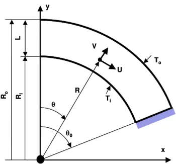
A domed cavity consists of concentric double-layer spherical domes with interior (Ri ) and exterior radii (Ro). The gap between the concentric layers is designated
by L. The dome shape is characterised by a truncation angle θ0 measured from
its axis of revolution. The truncation angle may vary from 0° to 180°. The case θ0 = 0° corresponds to concentric disks, θ0 = 90° to fully hemispherical domes
and θ0 = 180° to concentric spheres. The interior and exterior dome surfaces are
maintained at uniform temperatures Ti and To, respectively. The edges of the
enclosed space between the layers are assumed to be sealed and adiabatic. Owing to the thermal potential (Ti – To), a buoyancy-driven flow develops within
the enclosure. The flow is considered to be axi-symmetric since this
configuration is symmetrical with respect to the vertical axis (revolution axis). Only half of the cavity is, therefore, considered for the calculation. Figure 1 shows a schematic representation of the domed cavity cross section. The following assumptions are made:
• The fluid is incompressible.
• The buoyancy-driven flow within the enclosure is laminar.
• The physical properties of the fluid are constant, except for density in the body force terms. The constant physical properties are to be evaluated at the average temperature of the dome interior and exterior surfaces.
• The compression work and the viscous dissipation energy are neglected. Using the Boussinesq approximation, the fluid density is expressed as follows:
7
]
[
1
(
i)
i−
β
T
−
T
ρ
=
ρ
(1)The laminar, buoyancy-driven flow is governed by the Navier-Stokes equations. To obtain general solutions for the flow and temperature fields, the governing equations are non-dimensionalized using the following dimensionless variables:
) /( ) ( ; ) / ( / ) cos ( p ); / /( ); / /( v ); / /( u ; / 2 2 o i o i igR L T T T T P L t L V L U L R r − − = Φ ν ρ θ ρ + = ν = τ ν = ν = = (2)
The dimensionless transient Navier-Stokes equations in the spherical co-ordinate system read as follows:
Mass balance: 0 ) sin ( sin 1 ) ( 1 2 2 ∂θ θ = ∂ θ + ∂ ∂ u r v r r r (3)
Momentum balance: r-direction,
r S v r p v r u r v v v +∇ + ∂ ∂ − = θ ∂ ∂ + ∂ ∂ + τ ∂ ∂ 2 (4)
Momentum balance: θ-direction,
θ + ∇ + θ ∂ ∂ − = θ ∂ ∂ + ∂ ∂ + τ ∂ ∂ S u p r u r u r u v u 1 2 (5) Energy balance: Φ ∇ = θ ∂ Φ ∂ + ∂ Φ ∂ + τ ∂ Φ ∂ 2 Pr 1 r u r v (6) where ∇2
is the Laplace operator, and Sr and Sθ are dimensionless source terms,
) (sin sin 1 ) ( 1 2 2 2 2 θ ∂ ∂ θ θ ∂ ∂ θ + ∂ ∂ ∂ ∂ = ∇ r r r r r (7) θ − θ ∂ ∂ − − + θ ⋅ Φ ⋅ = cos 1 2 2 2 22 2 2cot r u u r r v u r Gr Sr (8) 2 2 ) sin ( 2 1 sin θ − θ ∂ ∂ + − θ ⋅ Φ ⋅ − = θ r u v r uv r Gr S (9) 2.1 Boundary Conditions
Equations (3) to (6) are subject to the no-slip and uniform temperature conditions at the cavity surfaces, and to the symmetry and adiabatic conditions at the axis of revolution and the edges, respectively. The boundary conditions in
dimensionless forms are translated as follows: 1 0; u : 0 , / 1 > = = Φ= = v r δ τ (10) 0 ; 0 u : 0 , / 1 1+ δ τ> = = Φ= = v r (11) 0 u : 0 , 0 = θ ∂ Φ ∂ = θ ∂ ∂ = > τ = θ v (12) 0 u : 0 , 0 ∂θ = Φ ∂ = = > τ θ = θ v (13)
The initial conditions at τ = 0 are that the fluid is quiescent and the heat transfer is by pure conduction.
The governing equations and the boundary conditions show that the flow within the enclosure is governed by four dimensionless parameters, namely the
Grashof number (Gr), the Prandtl number (Pr), the dimensionless gap spacing (δ), and the truncation angle θ0.
2.2 Evaluation of Heat Transfer
The domed cavity exchanges heat with the surrounding environments through its interior and exterior surfaces. The heat transfer at the interior and exterior
surfaces is evaluated as follows:
sin R 2 0 0 2 i θ θ ∂ ∂ π − = = θ
∫
d R T K q i R R i (14) θ θ ∂ ∂ π − = = θ∫
d R T K q o R R o 2 R sin 0 0 2 0 (15)Under the steady state conditions, the heat transfer at the interior surface must be equal to that at the exterior surface (qi = qo = q).
Nusselt numbers at the interior and exterior surfaces are defined as follows:
θ θ ∂ Φ ∂ θ − δ + = = δ = θ
∫
d r q q Nu r cond i i sin cos 1 ) 1 /( 1 / 1 0 0 0 (16) θ θ ∂ Φ ∂ θ − δ + = = δ + = θ∫
d r q q Nu r cond o o sin cos 1 1 / 1 1 0 0 0 (17)where qcond is the conductive heat flux in the absence of convection, given by the
following relation:
(
)
(
i o)
o i cond RR K L T T q =2π ⋅ 1−cosθ0 ⋅ / ⋅ − (18)Under steady state conditions, Nui = Nuo = Nu. Under such conditions, it is
practical to compute the convection film coefficient, which is useful for the calculation of the overall thermal conductance of the domed cavity. The
convective heat transfer from the interior to the exterior surface is expressed as follows: ) ( ) ( 5 . 0 Ao Ai hc Ti To q= + ⋅ ⋅ − (19) 9
Taking into account equation (16) or (17) and equation (18), the convection film coefficient is expressed as follows:
L K Nu 1 5 . 0 1 / 1 2 ⋅ ⋅ ⎭ ⎬ ⎫ ⎩ ⎨ ⎧ δ + δ + = c h (20)
3 Numerical Procedure
A commercial CFD package [11] was used to solve the governing equations (3) to (6). First, the equations were discretized using the control volume approach and the implicit and segregated schemes [12]. The second order upwind
scheme was used to discretize the momentum and energy equations (4) to (6). The SIMPLEC algorithm [13] was used for the pressure-velocity coupling and the PRESTO algorithm [13] was used for the pressure correction, which is
recommended for buoyancy-driven problems [11].
To get a converged solution, the residuals of the continuity, momentum and energy equations were monitored at each time step. The heat transfer rates at the exterior and interior surfaces of the cavity were monitored as well. The convergence was declared when all the calculated residuals, including changes in the surface heat transfer rate between two successive iterations, were less than 10-3. The convergence criterion was, however, fixed at 0.1 under some conditions of high values of Gr resulting in high flow velocities where the flow might be approaching transition to turbulence.
4 Inter-Model Comparison
For the model comparison purpose, the results obtained using the present numerical model were compared with those published in the literature on
concentric spheres [1,7,14]. For instance, Raithby and Hollands [14] employed the boundary conduction layer method to develop a correlation for the Nusselt number under steady state conditions. The correlation is expressed as follows:
{
* 1/4}
) ( 1; max c Ra Nu= ⋅ (21) 10where c is a coefficient and Ra* is a modified Rayleigh number, which are given by the following expressions:
{
3/5 4/5}
5{
1/4 * Pr) 861 . 0 Pr/( 74 . 0 ; ) 1 ( ) 1 ( 2 / Ra = ⋅ + δ + + δ + δ ⋅ = − c Ra}
(22)The coefficient (c) was calculated based on the experimental data of Bishop et al. [3].
Laouadi and Atif [1] presented correlations for the convective heat transfer in domed cavities heated from outside. The correlations cover broad ranges of dome shape and ratio of cavity gap spacing to radius.
Table 1 compares the values of the steady state Nusselt numbers predicted by the present model, Laouadi and Atif [1], Garg [7], and using equation (21) for concentric spheres θ0 = 180°, δ = 1, and Pr = 0.72. The interior sphere is
assumed hotter than the exterior one (Ti – To > 0). For this case, the flow
reaches the steady state conditions independently of the initial conditions. A grid of 60 x 60 nodes was used along the radial and circumferential directions. The grid was uniform in the circumferential direction and non-uniform in the radial direction with finer sizes near the boundaries. The present results agree very well (with a maximum error of 1%) with the numerical results obtained by Laouadi and Atif [1] and Garg [7]. Compared to correlation (21), the present model over-predicts the Nusselt number by about 14%. This difference is within the accuracy limit of the correlation due to the error involved in estimating the coefficient (c) based on the experimental data.
Table 2 shows another comparison with the numerical results by Laouadi and Atif [1] for domed cavities (θ0 = 90°) filled with air and heated from outside (To – Ti
> 0). For this case, the flow reaches the steady state conditions independently of the initial conditions. Both numerical results are in very good agreement with a maximum difference of 4%.
12
5 Results and Discussion
The simulation results are presented for the case where the interior cavity
surface is hotter than the exterior surface, and air fills the cavity gap (Pr = 0.72). The flow domain is discretized using a uniform and non-uniform mesh along the radial and circumferential directions, respectively. The mesh size is finer near the interior and exterior surfaces. Appropriate mesh sizes are selected according to the heating intensities (Gr) and the shape and gap thickness ratio of the cavity (θo, δ). For each gap thickness ratio, the results from the different mesh sizes
are compared for moderate and high values of Gr to ascertain mesh independent results. The mesh size is retained when the resulting values of Nu are less than 1% from a finer mesh size. Table 3 shows a typical effect of the mesh size on the Nusselt number for cavities with the gap ratio of δ=0.1 and truncation angle of θ0 = 30°. It can be concluded from Table 3 that the numerical results with a
minimum grid size of 60 x 60 nodes are mesh independent. For other cases where the flow is transient, the mesh size is determined for each cavity
configuration. The time step is fixed to 1 for most cases, except for cavities with low gap spacing ratios (δ < 0.1) where the time step is lowered to 0.01. In the sections that follow, typical thermal fields and flow patterns within the cavity, as well as heat transfer through the cavity, are presented for several combinations of the flow governing parameters (30o ≤ θ0 ≤ 90o; 0.01 ≤ δ ≤ 1; Gr ≤ 107). 5.1 Flow patterns in high profile cavities with θ0 = 90o
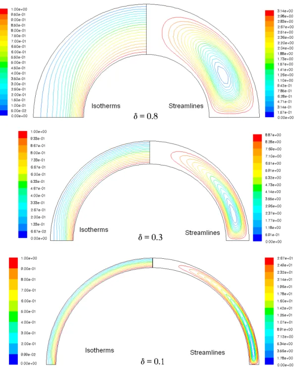
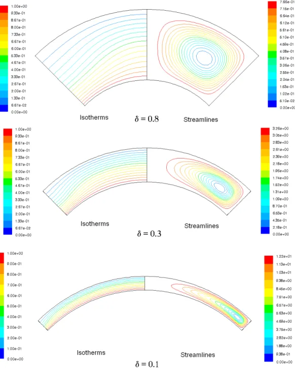
Figures 2 to 4 show the streamlines and isotherms for fully hemispheric cavities (θ0 = 90°) and three values of the gap spacing ratio (δ = 0.1, 0.3, 0.8) and
Grashof number (Gr = 103, 5x10⁴, 5x10⁶). The results for cavities with large gap spacing ratios (1≤ δ ≤ 0.5) indicate that the flow is mono-cellular and may reach the steady state conditions independently of the initial solutions. For cavities with moderate gap spacing ratios (0.2 < δ < 0.5), the flow pattern may be mono- or multi-cellular and steady state. The multi-cellular flow occurs at a Gr value of
13
~5x10⁶ or higher as shown in Figure 4. For small gap spacing ratios (0< δ ≤ 0.2) multi-cellular flow pattern occurs at Gr of ~5x10⁴ and higher.
In some cases for small gap spacing ratios (0< δ ≤ 0.2) the numerical results could depend on the starting initial solutions (corresponding to a given Grashof number) and converge to two different types of steady state flows. The first flow type is mono-cellular and is obtained when the initial solutions for the flow and temperature fields at a given value of Gr are set equal to those of a lower value of Gr. The second flow type is bi-cellular with an additional cell appearing at the top of the cavity. The latter flow type is obtained when the initial solutions are set equal to those of a higher value of Gr, and results in a quite higher heat transfer rate (around 6% difference for moderate values of Gr). Figure 5 shows typical streamlines for Grashof Number of 5x10⁴ (θο=90º, and δ=0.5) with step
increasing and step decreasing Grashof number. This flow bifurcation was also reported in previous numerical studies in concentric spheres [15]. In this study, the results for Nusselt numbers are calculated by step-increasing Gr.
For small gap ratios (δ ≤ 0.2), mono-cellular and steady state flows are observed for values of Gr < 5x10³ as shown in Figure 2. However, transient periodic and multi-cellular flows are observed for intermediate values of Gr (5x10³≤ Gr ≤ 5x10⁴). Figure 6 shows four periods of typical oscillations in the Nusselt number for Gr = 7.5x10³ and δ = 0.2. Figure 7 shows the corresponding cyclic flow pattern at points A, B and C of Figure 6. As shown in Figures 6 and 7, the Nu increases with the number of vortex cells in the cavity. There are five vortex cells in the cavity at point A or C where the corresponding Nu is high, and three cells at point B where the corresponding Nu is low. This observation was also
experimentally observed in concentric spheres [3-6]. For practical applications, the Nusselt number is averaged over three to five periods of oscillations,
∫
τ τ τ ⋅ τ − τ = 2 1 2 1 1 d Nu Nu (23) where τ1 and τ2 are the start and end times of a periodic cycle.For small gap spacing ratios (0< δ ≤ 0.2), as the Gr increases the number of vortex-cells increases in the flow, but at Gr ~5x10⁴ or higher some vortex-cells merged with the bigger vortex-cell at the bottom of the cavity and form a bigger vortex-cell that fills most part of the cavity. This drop in the number of vortex-cells results in a lower Nu. The sudden change in the Nu can be seen in Figure 14 at a gap spacing ratio of 0.1 when the Gr is increased from 5x10⁴ to 7.5x10⁴ (Ra* (1/4) changes from 2.6987 to 2.9866).
5.2 Flow patterns in medium profile cavities with θ0 = 45o
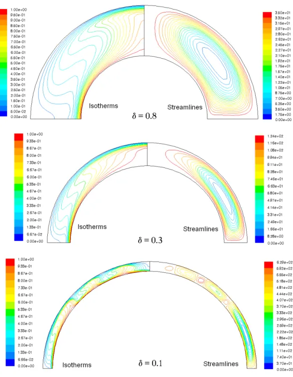
Figures 8 to 10 show the streamlines and isotherms for cavities with θ0 = 45°.
The results for cavities with large gap spacing ratios (0.5≤ δ ≤ 1) indicate that the flow is mono-cellular and may reach the steady state conditions independently of the initial conditions for the covered values of Gr. For cavities with moderate gap spacing ratios (0.2 < δ < 0.5), the flow pattern may become steady state and mono- or multi-cellular, depending on the value of Gr. Mono-cellular flows occur at low values of Gr ≤ 103
, and bi-cellular flows occur at moderate values of Gr (e.g., Gr = 5x10⁴). At high values of Gr (e.g., Gr = 5x10⁶), a big cell occupies most of the cavity space, and two additional small cells on top of each other appearing at the top of the cavity. For small gap ratios (δ≤ 0.2), the flow pattern may become mono-cellular and steady state at low values of Gr ≤ 103
, or multi-cellular and transient periodic at intermediate and high values of Gr > 5x10⁴. Similar to the results for θ0 = 90º, for Gr ~5x10⁶ and higher, small unstable
vortex-cells formed inside the big vortex-cell, which may indicate the flow transition from a laminar to turbulent flow.
5.3 Flow patterns in low profile cavities with θ0 = 30o
Figures 11 to 13 show the streamlines and isotherms for cavities with θ0 = 30°.
The results for cavities with large and intermediate gap spacing ratios (0.2 < δ ≤ 1) indicate that the flow is mono-cellular and may reach the steady state
conditions independently of the initial conditions for the covered values of Gr. For cavities with small gap spacing ratios (δ≤ 0.2), the fluid flow may reach the steady state conditions under all considered values of Gr, except for cavities with very small gap ratios (e.g., δ =0.01), where the flow may be transient periodic.
5.4 Correlations for heat transfer rates
Figures 14 to 16 show the variation of the time-averaged Nusselt number as a function of the modified Rayleigh number (Ra*)1/4 for cavities with θ0 = 90°, 45°
and 30°, respectively. Three typical gap spacings are considered: δ = 0.1, 0.3 and 0.8. For the three cavity shapes, the variation of the average Nusselt
number with the parameter (Ra*)1/4 shows a clear dependence on the cavity gap spacing δ. This dependence is more pronounced for low profile cavities (θ0 <
45°) than for fully hemispheric cavities (θ0 = 90°). The averaged Nusselt number
generally exhibits a linear profile under the steady state conditions, which usually occur at relatively high cavity gap spacings (δ > 0.3). Under the transient
periodic regime, which usually occurs at low cavity gap spacings (δ < 0.3), the average Nusselt number exhibits, however, a non-linear profile with some minor oscillations, particularly at low values of Ra*. The oscillations in the average Nusselt number are due to the structural change of the multi-cellular flow in the cavity, as previously mentioned. It should be added that the Nu is higher for low profile cavities than for fully hemispheric cavities.
In view of the foregoing results, the Nusselt number may be expressed as follows:
{
1; ( *)d/4}
max c Ra
Nu= ⋅ (24)
where the coefficients c and d depend on the cavity gap spacing δ and are to be determined for each cavity shape. These coefficients may be determined using regression techniques. Using the least-square curve-fitting method, one obtains the following relations for c and d:
For θ0 = 90°,
( )
(
( )
)
( )
(
( )
)
2 2 ln 33058 . 0 ln 10818 . 1 1 ln 27049 . 0 ln 88266 . 0 77923 . 0 δ ⋅ + δ ⋅ + δ ⋅ + δ ⋅ + = c (25)( )
(
( )
)
( )
(
( )
)
2 2 ln 51559 . 0 ln 15263 . 1 1 ln 50497 . 0 ln 12137 . 1 99443 . 0 δ ⋅ + δ ⋅ + δ ⋅ + δ ⋅ + = d (26) For θ0 = 45°, ⎪ ⎪ ⎪ ⎩ ⎪⎪ ⎪ ⎨ ⎧ ≤ δ δ − δ + δ − δ < δ + δ − δ + δ − = 1 . 0 269 . 120 461 . 61 284 . 8 201 . 1 1 1 . 0 006 . 0 056 . 0 173 . 0 542 . 0 190 . 1 3 2 2 2 if if c (27) 1 = d (28) For θ0 = 30°, 5 4 3 2 62163 . 20 44906 . 52 54738 . 46 73474 . 16 76732 . 0 68665 . 0 1 δ − δ + δ − δ + δ − = c (29) 4 3 2 88671 . 0 41794 . 2 34681 . 2 158027 . 1 81649 . 0 + δ− δ + δ − δ = d (30)Equations (25) to (30) are developed for the range of the Grashof numbers 0 < Gr ≤ 107 and cavity gap spacing ratios 0.01 ≤ δ ≤ 1. The regression coefficient for
the equations (25) to (30) is greater than 0.96, and the maximum average error over the considered ranges of Grashof numbers and gap thicknesses is less than
17
11%. The maximum error occurs at very small Grashof numbers (Gr < 104), where the correlations predict higher values of the averaged Nusselt number. Figure 17 shows a graphical comparison between the correlated and calculated averaged Nusselt numbers for cavities with θ0 = 90°, 45° and 30°.
Figure 18 shows the effect of the cavity gap spacing on the time-average Nusselt number evaluated at Gr = 104, 5x10⁵, and 106 for cavity shapes θo = 90°, 45° and
30°. The Nusselt number increases with the increase of the cavity gap spacing δ until reaching a maximum value then decreases to asymptotic value. The
maximum value of Nu varies with the Gr, but is almost independent of the cavity shape. For Gr values lower than 5x10⁵, the maximum Nu occurs around δ = 0.1. For higher Gr values, the maximum Nu occurs in the range δ = 0.2 to 0.5.
6 Conclusion
This paper addressed the laminar natural convection within several shapes of domed cavities heated from the inside surface. A commercial CFD package was used to solve the transient governing equations. The flow pattern and
temperature field within the cavity, and the convection heat transfer rate were computed. Practical correlations were also developed for the convection heat transfer coefficient, covering broad ranges of the parameters.
The results showed that the cavity flow may reach steady state conditions, or become transient periodic. The steady state flow occurs at relatively high cavity gap spacings (δ > 0.3), and is usually mono- or bi-cellular, depending on the Grashof number and cavity gap spacing ratio. However, the transient periodic steady state flow occurs at relatively low cavity gap spacing ratios (δ ≤ 0.2), and is usually multi-cellular, with a few small vortex cells at the top of the cavity and one big cell at the bottom part. The top cells gradually move to the bottom part where some of them merge with the bottom cell, hence forming one bigger cell. The latter may split into a number of smaller cells, or become smaller as new cells appear at the top part of the cavity, and so forth for subsequent cycles. This
18
behaviour resulted in periodic oscillations in the heat transfer with significantly higher rates than for steady state flows. Fully hemispheric cavities (θ0 = 90°)
yield usually about 20% less heat transfer than low profiles cavities (θ0 < 45°),
particularly for cavities with small gap spacing ratios (δ < 0.2). For a given cavity shape, there exists a critical gap spacing for which the Nusselt number reaches its maximum value, and then decreases to settle at an asymptotic value with increasing gap spacing. The critical gap spacing ratio was found to vary between δ = 0.1 and 0.5, depending mainly on the Gr.
7 Acknowledgement
This work was funded by the Natural Sciences and Engineering Research Council (NSERC), the National Research Council of Canada (NRC), the Panel for Energy Research and Development (PERD), British Colombia Hydro, and Natural Resources of Canada (NRCan). The authors are very thankful for their financial support.
8 References
[1] Laouadi A. and Atif M.R., Natural Convection Heat Transfer Within Multi-layer Domes, International Journal of Heat and Mass Transfer, 2001, Vol. 44, pp. 1973-1981.
[2] McGowan A.G. , Desjarlais A.O. and Wright J.L., 1998, “Simulation and testing of pyramid and barrel vault skylights”, ASHRAE Transactions, 1998, Vol.104, Part 1, pp. 832-844.
[3] Bishop E.H., Kolflat R.S., Mack L.R. and Scanlan J.A., 1964, “Convective heat transfer between concentric spheres”, Proceedings of the 1964 Heat Transfer and Fluid Mechanics Institute. Stanford University Press. California.
pp. 69-80.
[4] Bishop E.H., Mack L.R. and Scanlan J.A., 1966, “Heat transfer by natural convection between concentric spheres”, International Journal of heat and Fluid Flow, vol. 9, pp. 649-662.
19
[5] Scanlan J.A., Bishop E.H., and Powe R.E. and, 1970, “Natural convection heat transfer between concentric spheres”, International Journal of heat and Mass Transfer, vol. 13, pp. 1857-1872.
[6] Yin, S.H., Powe R.E., Scanlan J.A., and Bishop E.H., 1973. Natural
convection flow patterns in spherical annuli. International Journal of heat and Mass Transfer, vol. 16, pp. 1785-1795.
[7] Garg V.G., 1991, “Natural Convection Between Concentric Spheres”,
International Journal of Heat and Mass Transfer, vol. 35, no.8, pp. 1935-1945. [8] Chiu C.P. and Chen W.R. 1996, “Transient natural convection heat transfer
between concentric and vertically eccentric spheres”, International Journal of Heat and Mass Transfer, vol. 39, no. 7, pp. 1439-1452.
[9] Chiu C.P. and Chen W.R., 1996, “Transient natural convection heat transfer between concentric and vertically eccentric spheres with mixed boundary conditions”, Journal of Heat and Mass Transfer, vol. 31, pp. 137-143. [10] Chen W.R., 2005, “Transient natural convection of micropolar fluids
between concentric and vertically eccentric spheres”, Journal of Heat and Mass Transfer, vol. 48, pp. 1936-1951.
[11] Fluent Inc. 2005. FLUENT User’s Manual Version 6.2. Fluent Incorporated, Evanston, Illinois.
[12] Patankar S.V., 1980, “Numerical Heat Transfer and Fluid Flow”, Hemisphere, New York.
[13] Versteeg H.K. and Malalasekera W., 1995, “An Introduction to
Computational Fluid Dynamics: The Finite Volume Method”, Harlow: Pearson Prentice Hall.
[14] Raithby G.D. and Hollands K.G.T., 1975, “A general method of obtaining approximate solutions to laminar and turbulent free convection problems” Advances in Heat Transfer , vol. 11, pp. 266-315.
20
[15] Caltagirone J.P., Combarnous M., Mojtabai A., 1980, “Natural convection between two concentric spheres: transition toward a multi-cellular flow”, Numerical Heat Transfer, vol. 3, pp. 107-114.
Table 1 Comparison of Nusselt numbers for concentric spheres heated from the inside for δ = 1
Ra Present Model Laouadi and Atif [1] Garg [7] Raithby and
Hollands [14] 1000 1.10 1.10 1.10 1.00 3000 1.42 1.42 1.42 1.26 6300 1.74 1.74 1.74 1.52 10500 1.98 1.98 1.98 1.73 14000 2.13 2.13 2.13 1.85 21000 2.35 2.35 2.36 2.10 42000 2.77 2.76 2.78 2.44 91000 3.30 3.28 3.31 2.96 21
22
Table 2 Nusselt number comparison between the present model and the model of Laouadi and Atif [1] (θo=90o, δ=0.2 and To > Ti)
Grashof Number (Gr) Present Model Laouadi and Atif [1] Difference (%)
1.0E+03 1.03 1.00 3 2.5E+03 1.12 1.12 0 5.0E+03 1.28 1.33 4 7.5E+03 1.43 1.47 3 1.0E+04 1.54 1.58 2 2.5E+04 1.99 1.99 0 5.0E+04 2.40 2.36 2 7.5E+04 2.66 2.61 2 1.0E+05 2.86 2.81 2 2.5E+05 3.58 3.53 1 5.0E+05 4.24 4.20 1 7.5E+05 4.68 4.65 1 1.0E+06 5.02 4.99 1 2.5E+06 6.30 6.28 0 5.0E+06 7.47 7.47 0 7.5E+06 8.26 8.27 0 1.0E+07 8.87 8.88 0
23
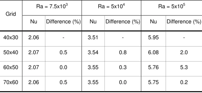
Table 3 Comparison of Nusselt number with different grid densities (θo=30o, δ =
0.1, and To < Ti). The percent difference is between two consecutive
grid densities.
Grid
Ra = 7.5x10³ Ra = 5x10⁴ Ra = 5x10⁵
Nu Difference (%) Nu Difference (%) Nu Difference (%)
40x30 2.06 - 3.51 - 5.95 -
50x40 2.07 0.5 3.54 0.8 6.08 2.0
60x50 2.07 0.0 3.55 0.3 5.76 5.3
θ V U R θ0 Ri Ro L Ti To y x θ V U R θ0 Ri Ro L Ti To y x
Figure 1 Schematic description of a domed cavity
Figure 2 Isotherms and streamlines for fully hemispheric cavities (θ0 = 90°) at Gr
= 103.
Figure 3 Isotherms and streamlines for fully hemispheric cavities (θ0 = 90°) at Gr
= 5x10⁴
Figure 4 Isotherms and streamlines for fully hemispheric cavities (θ0 = 90°) at Gr
= 5x10⁶
Figure 5: Flow bifurcation at Gr = 5x10⁴ (θο=90o, and δ=0.5). a) Solution obtained
by step-increasing Gr. b) Solution obtained by step-decreasing Gr
1 .5 2 1 .5 6 1 .6 0 1 .6 4 1 .6 8 1 .7 2 1 .7 6 1 9 0 0 1 9 0 5 1 9 1 0 1 9 1 5 1 9 2 0 1 9 2 5 1 9 3 0 1 9 3 5 1 9 4 0 1 9 4 5 1 9 5 0 T im e (s) Nu A B C
Figure 6 Typical oscillations in the Nusselt number at Gr = 7.5x10³ for θ0 = 90o
and δ = 0.2 (time step = 0.5)
Figure 7: Cyclic flow pattern at Gr = 7.5x10³ for θ0=90o, and δ=0.2
Figure 8 Isotherms and streamlines for medium profile cavities (θ0 = 45°)
at Gr =103.
Figure 9 Isotherms and streamlines for medium profile cavities (θ0 = 45°)
at Gr = 5x10⁴.
Figure 10 Isotherms and streamlines for medium profile cavities (θ0 = 45°)
at Gr = 5x10⁶.
Figure 11 Isotherms and streamlines for low profile cavities (θ0 = 30°)
at Gr = 103.
Figure 12 Isotherms and streamlines for low profile cavities (θ0 = 30°)
at Gr = 5x10⁴.
Figure 13 Isotherms and streamlines for low profile cavities (θ0 = 30°)
at Gr = 5x10⁶.
36
Figure 14 Nusselt Number profile as a function of (Ra*)1/4 for fully hemispheric cavities (θ0 = 90°). θo = 90o 0 2 4 6 8 10 12 0 2 4 6 8 10 12 14 1 Ra*1/4 Nu 6 δ = 0.8 δ = 0.3 δ = 0.1
37 θo = 45o 0 2 4 6 8 10 12 14 0 2 4 6 8 10 12 14 Ra* 1/4 Nu 16 δ = 0.8 δ = 0.3 δ = 0.1
Figure 15 Nusselt Number profile as a function of (Ra*)1/4 for medium profile cavities (θ0 = 45°).
θo = 30o 0 2 4 6 8 10 12 14 0 2 4 6 8 10 12 14 16 Ra*1/4 Nu δ = 0.8 δ = 0.3 δ = 0.1
Figure 16 Nusselt Number profile as a function of (Ra*)1/4 for low profile cavities (θ0 = 30°).
θo = 90 o 0 2 4 6 8 10 12 14 0 2 4 6 8 10 12 c (Ra*)d/4 Nu 14 δ = 1 δ = 0.8 δ = 0.5 δ = 0.4 δ = 0.3 δ = 0.2 δ = 0.1 δ = 0.01 correlation (a) θo = 45 o 0 2 4 6 8 10 12 14 0 2 4 6 8 10 12 1 c (Ra*)d/4 Nu 4 δ = 1 δ = 0.8 δ = 0.5 δ = 0.4 δ = 0.3 δ = 0.2 δ = 0.1 δ = 0.01 correlation (b) θo = 30 o 0 2 4 6 8 10 12 14 0 2 4 6 8 10 12 c (Ra')d/4 Nu 14 d = 1 d = 0.8 d = 0.5 d = 0.4 d = 0.3 d = 0.2 d = 0.1 d = 0.01 correlation (c)
Figure 17 Nusselt Number correlations for cavities with: a) θ0 = 90°; b) θ0 = 45°; c) θ0 = 30°.
Figure 18 Effect of the cavity gap spacing (δ) on the Nusselt Number

![Table 2 Nusselt number comparison between the present model and the model of Laouadi and Atif [1] (θ o =90 o , δ=0.2 and T o > T i )](https://thumb-eu.123doks.com/thumbv2/123doknet/14139731.470204/25.918.150.771.155.901/table-nusselt-number-comparison-present-model-model-laouadi.webp)