HAL Id: hal-00157824
https://hal.archives-ouvertes.fr/hal-00157824
Submitted on 24 Dec 2015
HAL is a multi-disciplinary open access
archive for the deposit and dissemination of
sci-entific research documents, whether they are
pub-lished or not. The documents may come from
teaching and research institutions in France or
abroad, or from public or private research centers.
L’archive ouverte pluridisciplinaire HAL, est
destinée au dépôt et à la diffusion de documents
scientifiques de niveau recherche, publiés ou non,
émanant des établissements d’enseignement et de
recherche français ou étrangers, des laboratoires
publics ou privés.
The Double Star Plasma Electron And Current
Experiment.
A.N. Fazakerley, P.J. Carter, G. Watson, A. Spencer, Y.Q. Sun, J. Coker, P.
Coker, D.O. Kataria, D. Fontaine, Z.X Liu, et al.
To cite this version:
A.N. Fazakerley, P.J. Carter, G. Watson, A. Spencer, Y.Q. Sun, et al.. The Double Star Plasma
Electron And Current Experiment.. Annales Geophysicae, European Geosciences Union, 2005, 23 (8),
pp.2733-2756. �10.5194/angeo-23-2733-2005�. �hal-00157824�
Annales Geophysicae, 23, 2733–2756, 2005 SRef-ID: 1432-0576/ag/2005-23-2733 © European Geosciences Union 2005
Annales
Geophysicae
The Double Star Plasma Electron and Current Experiment
A. N. Fazakerley1, P. J. Carter1,*, G. Watson1, A. Spencer1, Y. Q. Sun2, J. Coker1, P. Coker1, D. O. Kataria1, D. Fontaine3, Z. X. Liu2, L. Gilbert1, L. He1,**, A. D. Lahiff1, B. Mihaljˇci´c1, S. Szita1, M. G. G. T. Taylor1,***, R. J. Wilson1, M. Dedieu3, and S. J. Schwartz4
1Mullard Space Science Laboratory, University College London, Holmbury St. Mary, Dorking, Surrey, RH5 6NT, UK 2Center for Space Science and Applied Research, Chinese Academy of Sciences, P.O. Box 8701, 100080 Beijing, China 3Centre d’Etude des Environnements Terrestre et Plan´etaires, IPSL, 10–12 Av. de l’Europe, 78 140 V´elizy, France
4Space and Atmospheric Physics Group, The Blackett Laboratory, Imperial College London, Prince Consort Road, London,
SW7 2BW, UK
*now at: UK Astronomy Technology Centre, Royal Observatory Edinburgh, Blackford Hill, Edinburgh, EH9 3HJ, UK **now at: Department of Physics, University of Alberta, Edmonton, T6G 2J1, Canada
***now at: Research and Scientific Support Department, ESA/ESTEC/SCI-SH, Keperlaan 1, 2201 AZ Noordwijk ZH, The
Netherlands
Received: 8 April 2005 – Revised: 13 July 2005 – Accepted: 23 August 2005 – Published: 8 November 2005
Part of Special Issue “Double Star – First Results”
Abstract. The Double Star Project is a collaboration
be-tween Chinese and European space agencies, in which two Chinese magnetospheric research spacecraft, carrying Chi-nese and European instruments, have been launched into equatorial (on 29 December 2003) and polar (on 25 July 2004) orbits designed to enable complementary studies with the Cluster spacecraft. The two Double Star spacecraft TC-1 and TC-2 each carry a Double Star Plasma Electron and Current Experiment (PEACE) instrument. These two instru-ments were based on Cluster Flight Spare equipment, but differ from Cluster instruments in two important respects. Firstly, a Double Star PEACE instrument has only a single sensor, which must be operated in a manner not originally envisaged in the Cluster context in order to sample the full range of energies. Secondly, the DPU hardware was mod-ified and major changes of onboard software were imple-mented, most notably a completely different approach to data compression has been adopted for Double Star, which allows high resolution 3-dimensional distributions to be transmitted almost every spin, a significant improvement over Cluster. This paper describes these instruments, and includes exam-ples of data collected in various magnetospheric regions en-countered by the spacecraft which have been chosen to illus-trate the power of combined Double Star and Cluster mea-surements.
Keywords. Space plasma physics (Instruments and
techniques) – Magnetospheric physics
(Solar-wind-magnetosphere interactions; Magnetospheric configuration and dynamics)
Correspondence to: A. N. Fazakerley
(anf@mssl.ucl.ac.uk)
1 Introduction
The Double Star Project has placed two Chinese mag-netospheric research spacecraft, Tan Ce 1 and 2 (TC-1, TC-2) carrying Chinese and European instruments, into a near-equatorial orbit and a polar orbit, respectively. TC-1 was launched on 29 December 2003 and has a 27.4-h period, 28◦ inclination and geocentric apogee/perigee of 13.37 RE/1.09 RE. TC-2 was launched on 25 July 2004
and has an 11.5-h period, 90◦ inclination and geocentric
apogee/perigee of 7.01 RE/1.09 RE.
These orbits have been designed so that their MLTs (Mag-netic Local Times) of apogee are aligned with each other and with that of the Cluster orbits, during the summer of 2004, when all spacecraft have their apogee in the magnetotail. The polar orbiting Cluster and TC-2 spacecraft will maintain this phasing, although the MLT of apogee of TC-1 drifts slowly apart from the other spacecraft. The NASA Polar spacecraft MLT of apogee is also fairly similar, and again phase locked with Cluster. If we treat Cluster as a single observation point (albeit with special small-scale multi-point measurement ca-pabilities) we have a three or four spacecraft constellation well suited to simultaneously examining magnetotail pro-cesses both close to and far from the Earth, and similarly (on the dayside) to examining the dayside cusps at one or more sites while also making measurements at the low lati-tude magnetopause. This is a unique constellation, capable of making observations with which we can examine the drivers of global scale magnetospheric processes (in essence the final realisation of the original ISTP Geotail-Polar-Equator con-cept) and is orbiting at a time when upstream monitors, au-roral and ring current imaging satellites, and sophisticated ground based ionospheric monitors are all active to provide
2734 A. N. Fazakerley et al.: The Double Star Plasma Electron and Current Experiment
Table 1. Summary of resources used by a single Double Star PEACE instrument.
Mass DPU 2.12 kg
Sensor 1.92 kg
DPU radiation shield 1.44 kg Sensor radiation shield 1.03 kg
Total 6.52 kg
Power Average 3.8 W
Peak (during HV sweeps) 4.8 W
Telemetry Science 4472 bps
HK 152 bps
detailed supporting observations of the global context. A par-ticular advantage of the Cluster-Double Star combination is that several Double Star instruments, including PEACE are identical or near identical copies of Cluster instrumentation, which helps in carrying out comparative data analysis stud-ies. The project has been rather cost-effective as significant parts of the infrastructure (operational and for science data dissemination and analysis) developed for Cluster could be readily adapted for Double Star.
The PEACE instruments measure electrons from a few eV to 25 keV energies, covering the thermal plasma regime occupied by solar wind electrons, magnetosheath electrons and much of the magnetospheric plasma electron popula-tion. PEACE can measure the contribution of these elec-trons to magnetospheric currents, and measure convection of the plasma local to the spacecraft. PEACE can also de-tect field-aligned electrons which may have been acceler-ated elsewhere in the magnetosphere, providing an element of remote sensing capability (constrained to providing infor-mation on other regions linked by the magnetic field to the spacecraft location).
The two Double Star spacecraft TC-1 and TC-2 each carry a Double Star Plasma Electron and Current Experi-ment (PEACE) instruExperi-ment. In this paper we describe how and why these differ from Cluster-PEACE instruments, and include examples of data collected in various magnetospheric regions encountered by the spacecraft, illustrating the power of combined Double Star and Cluster measurements.
2 Description of instruments
2.1 Introduction
The Double Star PEACE instruments were produced by reusing Cluster Flight Spare hardware, supplemented with some new components. Modifications to existing hardware were kept to a minimum. A complete flight-ready Cluster II PEACE instrument, consisting of two sensors (LEEA and HEEA) and a Data Processing Unit (DPU), was available.
In addition, the PEACE Flight Spare DPU from the ill-fated Cluster (I) mission of 1996 was available in partially disas-sembled form.
In order to provide two instruments, the Double Star TC-1 PEACE instrument was produced using the HEEA sensor and the Cluster II DPU, while the TC-2 PEACE instrument was produced using the LEEA sensor and the Cluster I DPU. Instrument resources are summarised in Table 1. The Clus-ter 1 DPU was upgraded to ClusClus-ter II specifications. Hard-ware modifications were made to both DPUs in order to en-sure compliance with export control regulations, and exten-sive modifications to onboard software were required as a consequence, including removal of onboard moments deter-mination capability.
The Cluster II PEACE instruments (Fazakerley et al., 20051, Johnstone et al., 1997) were built by a consortium consisting of Mullard Space Science Laboratory of Uni-versity College London, Rutherford Appleton Laboratory (RAL) and the Norwegian Defence Research Establishment (NDRE, also known as FFI). The work to produce the Double Star PEACE instruments was carried out solely by MSSL, although the new science data compression software was de-veloped at MSSL from a study led by colleagues at the Centre d’Etude des Environnements Terrestre et Plan´etaires (CETP). The instrument preparation phase proceeded on a very chal-lenging schedule, as may be apparent from the interval be-tween the agreement bebe-tween CNSA and ESA to cooperate on the mission (9 July 2001) and the launch of the first space-craft in December 2003.
2.2 Comparison of Cluster and Double Star design con-straints
The most obvious change is the use of only one sensor unit for each Double Star instrument. Financial and time con-straints prevented the production and calibration of two new sensor units, which would have been needed to produce two dual sensor instruments.
The telemetry resource available to PEACE on the Double Star spacecraft is significantly larger than the standard Clus-ter telemetry rate, and is still larger “per sensor” as data is generated from only one sensor on Double Star, rather than two on Cluster.
The power, telecommand and telemetry interface for the Cluster-derived payload was handled by the Payload Data Management System (PDMS) which was produced by the Centre for Space Science and Applied Research (CSSAR) in Beijing and designed to closely conform to the Cluster spacecraft-payload interface. This was done to facilitate the incorporation of the European payload onto the Chinese satellite bus.
The Double Star spacecraft both spend a significant frac-tion of their orbits within the outer electron radiafrac-tion belt,
1Fazakerley, A. N., Carter, P. J., Watson, G., et al.: The
Clus-ter II Plasma Electron and Current Experiment, Ann. Geophys., in preparation, 2005.
A. N. Fazakerley et al.: The Double Star Plasma Electron and Current Experiment 2735
33
Figure 1. Illustration of the principle of the Top Hat electrostatic analyser. The voltage
applied to the analyser hemispheres diverts electrons (shown in blue) of a specific narrow
band of energy and arriving within the acceptance angle ∆Ψ through the analyser to the
detector, while electrons of other energies (e.g. in red) strike one of the analyser
hemispheres and are not detected. The semi-annular microchannel plate amplifies the
signal of an electron reaching it, and the resulting charge cloud is detected by one of 12
segments of the anode beneath, giving information about the electron arrival direction θ.
The Top Hat design is able to provide a focussed spot in the detector plane for a parallel
electron beam arriving from anywhere in the aperture plane. At times when the aperture
looks sunward, the majority of photons (black wiggly arrow) pass through the aperture
and do not find their way to the detector.
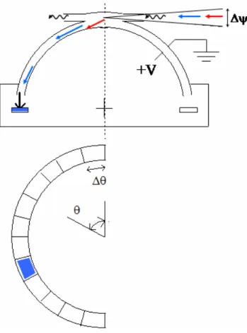
Fig. 1. Illustration of the principle of the Top Hat electrostatic
anal-yser. The voltage applied to the analyser hemispheres diverts elec-trons (shown in blue) of a specific narrow band of energy and ar-riving within the acceptance angle 19 through the analyser to the detector, while electrons of other energies (e.g. in red) strike one of the analyser hemispheres and are not detected. The semi-annular microchannel plate amplifies the signal of an electron reaching it, and the resulting charge cloud is detected by one of 12 segments of the anode beneath, giving information about the electron arrival direction θ . The Top Hat design is able to provide a focussed spot in the detector plane for a parallel electron beam arriving from any-where in the aperture plane. At times when the aperture looks sun-ward, the majority of photons (black wiggly arrow) pass through the aperture and do not find their way to the detector.
and also cross the proton belt. Cluster, with a higher perigee and a polar orbit, never encounters the proton belt and crosses quite rapidly through the outer electron belt. The origi-nal design specification for Cluster prohibited operations be-low 35 000 km altitude. The Cluster PEACE instrument was therefore designed to handle a 20–30 krad dose and without the specific anti-latchup protection that would be appropriate for a proton belt traversing instrument. Additional protection was therefore provided for the Double Star PEACE electron-ics subsystems, as described below.
Payload accommodation is handled differently on the Double Star spacecraft. The experiment platform has a smaller diameter and a cylindrical solar cell support struc-ture both above and below the experiment platform, whereas on Cluster there was only one solar cell cylinder below the
34 Figure 2. Illustration of instantaneous field of view of a Double Star PEACE sensor. Left: Side view of spacecraft, spin axis points close to ZGSE, the “look” directions from which
electrons arrive to be measured by the 12 anodes are indicated. Right: Top view of spacecraft, showing instantaneous field of view (elevation acceptance angle) also illustrating configuration of magnetometer booms (note that on TC-1 the STAFF boom is not deployed).
Fig. 2. Illustration of instantaneous field of view of a Double Star
PEACE sensor. Left: Side view of spacecraft, spin axis points close to ZGSE, the “look” directions from which electrons arrive to be measured by the 12 anodes are indicated. Right: Top view of space-craft, showing instantaneous field of view (elevation acceptance an-gle) also illustrating configuration of magnetometer booms (note that on TC-1 the STAFF boom is not deployed).
experiment platform. The main significance for PEACE was the need to adapt the PEACE thermal blanket design. The re-lationship between sun sensor look direction, magnetometer sensor orientations and PEACE look directions also differs from Cluster, requiring modification to software which uses this positioning information.
2.3 Sensor description
Each sensor consists of a “Top Hat” electrostatic analyser with an annular microchannel plate chevron pair (MCP) and segmented anode to provide position sensitive detection of arriving electrons, together with a supporting Sensor Elec-tronics Unit. Figure 1 illustrates the general principle of the PEACE electrostatic analyser, showing how photons typi-cally travel right through the collimator (photons do not en-ter the collimator at all unless the sensor faces sunward), and only electrons with the selected energy are allowed to reach the detector. The “Top Hat” design ensures that all electrons on mutually parallel trajectories will be focused by the anal-yser to the same part of the MCP, whichever part of the aper-ture they enter from. The detector anode is divided into 12 equal parts, corresponding to 15◦ resolution in the “polar” angle. The PEACE analyser is mounted with its field of view fan lying perpendicular rather than tangential to the space-craft surface, as shown in Fig. 2, in order to minimise the entry into the aperture of photoelectrons and secondary elec-trons from the local spacecraft surface. Consequently, only 180◦ of the 360◦field of view available in principle with a Top Hat analyser are in use (hence the semi-annular MCP and anode). Figure 2 illustrates the direction from which electrons arrive to be counted on anodes 0 to 11, in terms of the spacecraft spin axis, which is intended to point close to the GSE (Geocentric Solar Ecliptic) Z direction. (Note that in practice some departure from this ideal spin axis ori-entation occurred as the mission proceeded).
2736 A. N. Fazakerley et al.: The Double Star Plasma Electron and Current Experiment
Table 2. Summary of sensor characteristics. Note that azimuthal resolution depends on sweep mode (see also Table 3).
Sensor HEEA (TC-1) LEEA (TC-2)
Energy Range ∼1 eV to 26 keV ∼1 eV to 26 keV Energy Resolution, dE/E 17.5±0.3 12.9±0.2
k-factor 6.22±0.05 6.14±0.05
Field of view: polar 180◦ 180◦
Field of view: azimuthal 4◦ 3◦
Angular resolution: polar 15◦ 15◦ Angular resolution: azimuthal 22.5◦, 11.25◦, 5.625◦ 22.5◦, 11.25◦, 5.625◦ Geometric factor, per 15◦zone 6.0×10⁻⁸m2sr eV/eV 1.6×10⁻⁸m2sr eV/eV
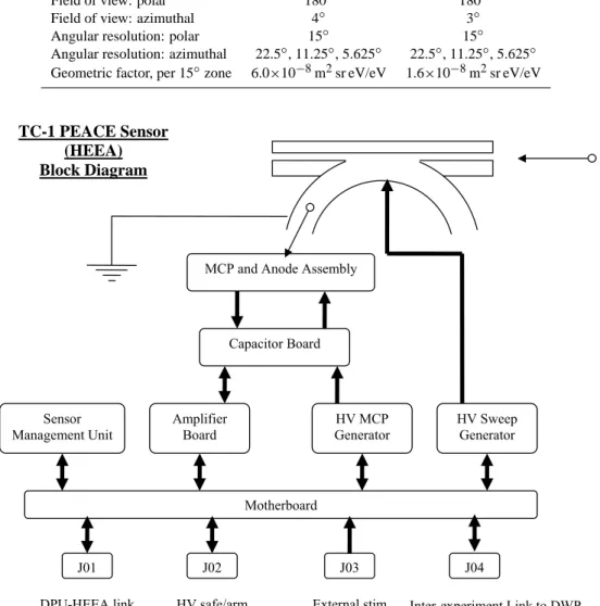
35 Figure 3. Block Diagram of TC-1 PEACE Sensor (a HEEA). The small circles with attached thin arrows represent electrons approaching and travelling through the
electrostatic analyser to be detected at the MCP and Anode Assembly. The LEEA sensor is identical except that J04 is absent.
DPU-HEEA link Inter-experiment Link to DWP Capacitor Board
MCP and Anode Assembly
TC-1 PEACE Sensor (HEEA) Block Diagram Motherboard Sensor Management Unit Amplifier Board HV MCP Generator HV Sweep Generator J01 J02 J03 External stim HV safe/arm J04
Fig. 3. Block Diagram of TC-1 PEACE Sensor (a HEEA). The small circles with attached thin arrows represent electrons approaching and
travelling through the electrostatic analyser to be detected at the MCP and Anode Assembly. The LEEA sensor is identical except that J04 is absent.
The sensors conform to the Cluster II specification (Faza-kerley et al., 20051) which is similar to the Cluster I specifi-cation (Johnstone et al., 1997), except that the sensor anodes were modified to delete the fine angular resolution capability and the MCP resistivity was altered, in both cases to improve performance under high electron fluxes. The data readout sub-systems were not changed, so the sensor still delivers data to the DPU from 4 fine angular resolution zones as well as the 12 coarse resolution anodes. Since the fine angular res-olution zones are no longer electron detecting, any data from them is received but then discarded by the Data Processing Unit software. The sensor geometric factors are just as for Cluster. Sensor characteristics are summarised in Table 2.
Figure 3 shows a block diagram for the TC-1 (HEEA) sen-sor. The only differences between the HEEA sensor and the LEEA sensor used on TC-2 are (i) the analyser head of a HEEA is designed to allow in more electrons than a LEEA in the same plasma environment, i.e. the Geometric Factor is larger, and (ii) the HEEA Sensor can be connected by an Inter-Experiment Link (IEL) to the TC-1 Digital Wave Processor (DWP) experiment so that the Particle Correla-tor experiment (software running inside the DWP processor) has access to detailed timing information about each arriv-ing electron measured at a selectable PEACE anode. As we discuss below, the link with DWP is why HEEA is on TC-1 and not TC-2.
A. N. Fazakerley et al.: The Double Star Plasma Electron and Current Experiment 2737
Table 3. PEACE electrostatic analyser HV sweep modes.
Sweep mode Energy steps per sweep Step size Sweep period Sweeps per spin Measurement Flyback
Interval/Tacc Interval/Tacc
LAR 60 1 60 4 16
MAR 60 2 30 2 32
HAR 30 2 15 1 64
The analyser HV Sweep Generator is capable of providing 88 distinct voltages, the first 16 of which are linearly spaced, and the remaining 72 of which are logarithmically spaced. For science data collection the analyser voltage is repeatedly swept through a range of values so that a range of electron en-ergies is sampled during each “energy sweep”. Three energy sweep modes are available; Low, Medium or High Angular Resolution (LAR, MAR or HAR). Both a LAR and a MAR sweep jump down 60 consecutive voltage steps each sweep, but a LAR sweep duration is twice that of a MAR sweep. An HAR sweep covers 30 consecutive voltage steps per sweep in half the time of a MAR sweep. Each sweep begins with a “flyback” time interval during which the voltage returns to the highest voltage reached during the sweep; the flyback du-ration is defined differently for each sweep mode, as shown in Table 3.
Measurements are made by counting the number of elec-trons striking each anode during an accumulation period Tacc,
defined as Tspin/1024 where Tspinis the satellite spin period.
For a nominal 4.0 s spin, Tacc=3.9 ms. The accepted
tron energy at any given moment is controlled by the elec-trostatic potential of the analyser inner hemisphere. There are 16 LAR sweeps, 32 MAR sweeps or 64 HAR sweeps per spin; hence the increase in spin phase (azimuthal) angle reso-lution implied in the sweep mode names. The LAR mode has the best energy resolution, as it changes analyser voltage by stepping down one level during each accumulation time. The MAR and HAR modes share the same (lower) energy resolu-tion; in both cases the analyser voltage steps down two levels during an accumulation time. These “steps” are not near-instantaneous drops in voltage from one level to the next, after which the voltage sits at a level for the remainder of the accumulation time. Instead, the sweep voltage is allowed to decay exponentially between the top 72 levels, and does so over a period of about 1.8 ms, so that the “logarithmic” part of the sweep is very close to a smooth exponential decay in MAR and HAR modes, but somewhat more step-like in LAR mode. The calibration process involves determination of a “representative energy” for each “step” in each sweep mode. Table 3 summarises all these characteristics of the sweep modes. The MAR mode is used most often in orbit. In all cases, during a single spin, the instrument measures 11 520 values from the 12 anodes (excluding data collected during flybacks and fine zones, which is not useful). The en-ergy range that is covered by a given sweep is controlled by
36 Figure 4. Cross section through a PEACE Sensor electrostatic analyser
Figure 5. A view of the TC-1 PEACE Sensor. Note the analyser head radiation shield material intended to protect the MCP, in particular the pie-slice plates and the enhanced thickness rim of the cylinder towards the aperture side of the sensor head.
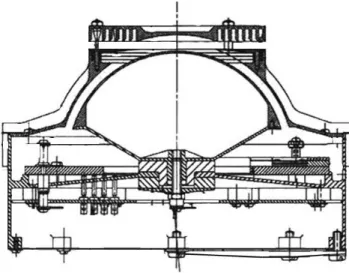
Fig. 4. Cross section through a PEACE Sensor electrostatic
anal-yser.
the “sweep preset” value, which may be varied by telecom-mand.
The sensitivity of the MCP is controlled by adjusting the voltage applied to the microchannel plates. The capability is useful during operations, as the sensitivity is expected to decline with use in orbit, particularly if the sensor is exposed to high fluxes for a prolonged period.
The analyser head has been designed to minimise the number of photons, photoelectrons and secondary electrons which are able to reach the detector. Figure 4 shows a cross-section through an analyser head which illustrates some of the relevant design features. As discussed in Johnstone et al. (1997), computer simulations predicted that arriving elec-trons and UV photons which strike the lip where a hole is cut in the outer hemisphere would be a major source of sec-ondary electrons and photoelectrons. Therefore a ring baffle was introduced in this region in order to reduce the surface area from which such electrons would be emitted on paths that reach the detector. Baffles in the roof of the input col-limator are similarly intended to reduce the flux of primary electrons and UV photons reaching the inter-hemisphere gap region. The hemispheres and the entrance aperture are coated in black copper oxide, applied by the EBONOL-C process, which provides further absorption of UV photons and sec-ondary electrons.
2738 A. N. Fazakerley et al.: The Double Star Plasma Electron and Current Experiment
36 Figure 4. Cross section through a PEACE Sensor electrostatic analyser
Figure 5. A view of the TC-1 PEACE Sensor. Note the analyser head radiation shield material intended to protect the MCP, in particular the pie-slice plates and the enhanced thickness rim of the cylinder towards the aperture side of the sensor head.
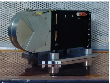
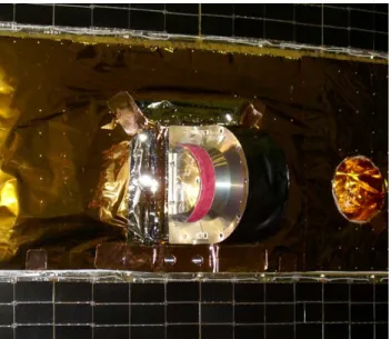
Fig. 5. A view of the TC-1 PEACE Sensor. Note the analyser head
radiation shield material intended to protect the MCP, in particular the pie-slice plates and the enhanced thickness rim of the cylinder towards the aperture side of the sensor head.
Inspection of Fig. 4 demonstrates that all paths that pen-etrating radiation might take through the analyser head to reach the MCP will pass through a significant amount of material. The design is intended to put 5 to 6 mm of Alu-minium or material of equivalent mass density in every di-rection. The resultant shielding is expected to be adequate to stop all electrons of energy up to 2 MeV (although not the Bremsstrahlung), and significant fractions of electron fluxes at higher energies up to perhaps 10 MeV, as well as pro-tons up to 30 MeV. Figures 5 and 6 show photographs of a PEACE sensor including the enhanced radiation shielding on the analyser head.
The ground calibration work done on the sensors for Clus-ter II was repeated for Double Star in sufficient detail to con-firm that there were no changes. In the process, the integrity of the sensors was confirmed, to ensure that no damage had occurred after their journey to and from the Cluster launch site (Baikonur, Kazakhstan).
Double Star TC-1 carries a DWP unit as part of the STAFF-DWP instrument, and DWP is host for the Particle Correlator software (see Cornilleau-Wehrlin et al., 2005, this issue). In order to enable the utilisation of the Correlator ca-pability on Double Star, it was decided to fly the HEEA sen-sor on the TC-1 spacecraft. Since HEEA has greater sensitiv-ity than LEEA it would have been preferable to use LEEA on TC-1, at least from the perspective of magnetosheath mea-surements, since HEEA sensors often saturate in the high electron fluxes encountered in the magnetosheath. The Cor-relator software generates autocorrelation functions which may enable examination of the electron behaviour at higher time resolution than the ∼3.9 ms PEACE measurements, and in particular to examine wave-particle interactions, e.g. en-abling study of processes generating the diffuse aurora.
37 Figure 6. TC-1 PEACE DPU and Sensor together with the radiation shields for the electronic sub-systems.
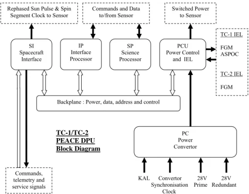
Figure 7. Block Diagram of PEACE DPU
Rephased Sun Pulse & Spin Segment Clock to Sensor
Commands, telemetry and service signals
Backplane : Power, data, address and control IP Interface Processor SP Science Processor SI Spacecraft Interface PCU Power Control and IEL PC Power Convertor Commands and Data
to/from Sensor
Switched Power to Sensor
KAL Convertor 28V 28V Synchronisation Prime Redundant Clock TC-1 IEL FGM ASPOC TC-2 IEL FGM TC-1/TC-2 PEACE DPU Block Diagram
Fig. 6. TC-1 PEACE DPU and Sensor together with the radiation
shields for the electronic sub-systems.
2.4 Data processing unit description
Figure 7 shows a block diagram of a PEACE Data Processing Unit (DPU), illustrating the main sub-systems and informa-tion flow
The TC-1 DPU could have been flown in its Cluster II Flight Spare configuration, except for the requirement that no components subject to export control regulations be used in Double Star payload provided by ESA. Unfortunately, the 64-kbyte SRAM components used for Cluster are export re-stricted. Within the constraints of predicted radiation dose and accommodation available within the existing DPU box, the only alternative was to replace the Cluster SRAMs with non-restricted 16-kbyte SRAMs. In addition, unused inter-faces applicable only for Cluster (e.g. to the second sensor, the IEL link to EDI) were closed off.
For TC-2, more extensive changes were required, in or-der to bring the Cluster I heritage DPU up to Cluster II DPU build standard. In particular, a suitable power converter was purchased (the MCP specification changed from Cluster I to Cluster II, affecting power requirements) and new SI and PCU cards were built. However, the Cluster I T222 transput-ers were not replaced with Cluster II style T225 transputtransput-ers. A Double Star PEACE Data Processing Unit (DPU) thus consists of a power converter and switching card, a spacecraft interface card and two processor cards. Each processor card is loaded with a single Transputer, 16 Kbytes of SRAM, a 0.5 KByte Bipolar PROM and 64 Kbytes of EEPROM.
The 16 kbyte SRAM per processor constraint is very se-vere, as the RAM must:
(i) accommodate the software used by the transputers during run time in order to achieve the required speed from the pro-cessor;
(ii) house data arriving from the sensor (at an incoming data rate of 8 kbytes per second) – note that there is not sufficient RAM to store all the data delivered during one 4-s spin at one time;
A. N. Fazakerley et al.: The Double Star Plasma Electron and Current Experiment 2739
37 Figure 6. TC-1 PEACE DPU and Sensor together with the radiation shields for the electronic sub-systems.
Figure 7. Block Diagram of PEACE DPU
Rephased Sun Pulse & Spin Segment Clock to Sensor
Commands, telemetry and service signals
Backplane : Power, data, address and control IP Interface Processor SP Science Processor SI Spacecraft Interface PCU Power Control and IEL PC Power Convertor Commands and Data
to/from Sensor
Switched Power to Sensor
KAL Convertor 28V 28V Synchronisation Prime Redundant Clock TC-1 IEL FGM ASPOC TC-2 IEL FGM TC-1/TC-2 PEACE DPU Block Diagram
Fig. 7. Block diagram of PEACE DPU.
(iii) contain the science telemetry buffer in which processed data is stored prior to transmission to the PDMS telemetry sub-system, (at an outgoing data rate of 2.2 kbytes per sec-ond).
The difficulties associated with this reduction in available RAM required that we develop new DPU processor software as discussed below.
On both spacecraft, the Inter-Experiment Link (IEL) be-tween FGM (Carr et al., 2005, this issue) and the PEACE DPU was retained, to allow PEACE access onboard to raw FGM data, for use in production of onboard pitch-angles. Similarly, on TC-1 the IEL between PEACE and ASPOC is used to allow ASPOC to receive PEACE onboard estimated values of the spacecraft potential.
2.5 Radiation shields
Pre-launch analysis projected a total dose while shielded by 4 mm Aluminium equivalent as ∼60 krad (Si) for TC-1 and
∼67 krad (Si) for TC-2.
The PEACE sensor and DPU electronics were designed for the 2 year Cluster mission radiation environment (20– 30 krad) and as such require additional protection for the Double Star environments. CNSA generously allowed us sufficient mass resource to provide this protection by build-ing 4 mm thick aluminium radiation shields, which are placed around the existing DPU and Sensor. These are il-lustrated in Fig. 6. Together with the 0.6 mm thick DPU and Sensor housings, the shields should stop protons with ener-gies up to 30 MeV and electrons with enerener-gies up to 1 MeV. According to the commonly used AP8 radiation belt
mod-els (Sawyer and Vette, 1976), the shield provides full pro-tection against protons for L>3.5. The outer electron belt is rather variable, and at times can have significant fluxes of
>1 MeV electrons. Further shielding is provided by space-craft components including the solar cell arrangement, ex-periment platform and batteries, but is present for less than half of the 4π solid angle of possible arrival directions for energetic particles. The detector radiation shielding has been discussed in the sensor description (see Sect. 2.3 above).
2.6 Thermal blankets
The thermal blanket protection around the PEACE sensors on Cluster was designed by the PEACE team, and procured from EADS Astrium Ltd. Additional units were bought for Double Star. It was hoped that the blankets could be used in just the same way for Double Star as for Cluster, but accommodation constraints required some modifications to achieve closure with the spacecraft thermal protection sys-tem. A technique for adapting the Cluster-design PEACE blankets was developed. A newly purchased thermal blan-ket was used for TC-2 PEACE, however TC-1 PEACE used a Cluster Flight Spare blanket. The thermal blankets were effective, and in fact the Double Star spacecraft is a warmer environment for a PEACE instrument than a Cluster space-craft.
The blankets were required in order to provide proper thermal insulation, and in addition to meet stringent elec-trical conductivity requirements to ensure that no differen-tial charging of the spacecraft surface arises. Success in this respect ensures that the trajectories of electrons arriving at
2740 A. N. Fazakerley et al.: The Double Star Plasma Electron and Current Experiment
38 Figure 8. Photograph of TC-2 PEACE Sensor head showing arrangement of electrostatic conductive materials; spacecraft and PEACE thermal blankets and also solar cells above and below the experiment platform. Note the larger collimator of a LEEA sensor vs. the TC-1 HEEA sensor.
Figure 9. Close up of HEEA Sensor Head showing thermal blanket closeout; note electrically conductive material places over the epoxy used to lock the screw heads.
Fig. 8. Photograph of TC-2 PEACE Sensor head showing
arrange-ment of electrostatic conductive materials; spacecraft and PEACE thermal blankets and also solar cells above and below the experi-ment platform. Note the larger collimator of a LEEA sensor vs. the TC-1 HEEA sensor.
the sensor aperture will not be affected by localised electric fields from areas of spacecraft surface material which have become charged to different potentials than the surrounding spacecraft surface. The mounting system includes the use of a metal band to hold the blanket in place against the cylindri-cal Analyser Head, which is attached by a number of small screws. The screws are secured by small quantities of (non-conductive) epoxy, which are covered with a disk shaped patch of aluminium tape using conductive adhesive to ensure continuity of electrostatic conductivity in the vicinity of the aperture, as shown in Figs. 8 and 9. Extensive testing of the conductivity of the sensor head, thermal blanket and indeed the entire spacecraft surface was carried out by the space-craft team, shortly before launch, to ensure that the required standard had been achieved. Some differences in conductiv-ity were noted between newly purchased and older thermal blankets, with better performance from the older blankets.
2.7 Onboard software
2.7.1 Onboard software requirements
The software requirements for the PEACE DPU onboard the Double Star spacecraft can be summarised as:
1. To provide a software interface to service the data being streamed from the PEACE Sensor to the DPU.
2. To provide a software interface to the PDMS that is ca-pable of receiving commanding and servicing signals, including telemetry requests.
3. To provide housekeeping telemetry data with which to monitor the health of the instrument.
38 Figure 8. Photograph of TC-2 PEACE Sensor head showing arrangement of electrostatic conductive materials; spacecraft and PEACE thermal blankets and also solar cells above and below the experiment platform. Note the larger collimator of a LEEA sensor vs. the TC-1 HEEA sensor.
Figure 9. Close up of HEEA Sensor Head showing thermal blanket closeout; note electrically conductive material places over the epoxy used to lock the screw heads.
Fig. 9. Close up of HEEA Sensor Head showing thermal blanket
closeout; note electrically conductive material places over the epoxy used to lock the screw heads.
4. To return as much as possible of the Sensor data via the DPU-PDMS telemetry interface using a scheme that can be interpreted on the ground.
5. To provide all data that is required to commission the instrument in real time, in the housekeeping telemetry.
6. To provide a command interpreter for all required DPU and Sensor functions.
7. To provide functionality to boot the DPU.
8. To provide software patching capabilities.
2.7.2 Double Star PEACE software architecture
One of the DPU processor cards is designated to service the PDMS interface (the Interface Processor, or IP), while the other handles the incoming data from the Sensor (the Sci-ence Processor, or SP). The IP code is designed to be en-tirely event driven, imposing significant timing constraints on the response time and latency that can be tolerated before an event is serviced. The SP code works in synchronisation with the spacecraft spin.
The software for the PEACE DPU is divided into three lev-els. Level 1 consists of boot code to initialise the Transputer on each of the processor cards, and provides basic functions to “peek” and “poke” bytes into memory. This code also al-lows execution of the Level 2 software. Level 2 provides a comprehensive set of software patching and memory analy-sis facilities. It also provides functionality to select a range of “Application Codes” that constitute the final level of soft-ware. The first two levels of the software are common to both the processor cards. The final level is specific to the Interface or Science Processor that it is running on.
There are several application codes available in the Double Star PEACE software. For two-processor operations, there are both a main application code and a backup application
A. N. Fazakerley et al.: The Double Star Plasma Electron and Current Experiment 2741
code. Each contains full housekeeping data generation code as well as commanding, event handling, sensor data recep-tion and spacecraft potential estimarecep-tion code. In addirecep-tion it is possible to swap the identity of the processor cards, pro-viding redundancy should the link between the sensor and the SP processor fail – since the second processor is also linked to the sensor and could take on the SP functions instead.
There is also a single processor code that can generate a limited reduced resolution 3-D dataset (known as “3DR”) us-ing quasi-log compression (as on Cluster II PEACE), for use in the event of failure of either processor.
The main two-processor application code is an implemen-tation of JPEG compression designed to allow transmission of the full measured distribution at spin rate on a nearly con-tinuous basis. In this scenario, the transmitted 3-D distri-bution contains a factor 8 more values than 3DR, and both moments and pitch angles are determined using ground data processing software. The method offers better data resolu-tion and so is preferred. The energy resoluresolu-tion is twice that of 3DR, for the case of the most commonly used MAR sweep mode, allowing more accurate estimation of spacecraft po-tential in ground data analysis than from 3DR. We describe this implementation in more detail below.
The backup two-processor application code is a reduced capability version of the Cluster II code, which uses quasi-log data compression. The Cluster II capabilities of onboard moments determination and onboard magnetic field axis es-timation (from symmetry of the measured distribution) were removed. The capability to store 3-D distributions was lim-ited to the Cluster 3DR distribution applied to a single sen-sor. Onboard production of pitch angle distributions (adapted for the single sensor-only case), was retained, implemented essentially as for Cluster II, using FGM data from the Inter-Experiment Link. The reduced memory resources, compared to Cluster, made it impossible to retain the onboard moments determination software.
An onboard dead-time correction capability is not in-cluded, unlike the Cluster case where it was required since moments calculations are performed onboard. For Double Star, such calculations and prior dead time corrections are performed on the ground.
2.7.3 Commanding
In order to reduce (relative to Cluster) the number of mands transmitted to the spacecraft, the number of mands to be stored onboard the spacecraft and also the com-mand checking workload during operations, we introduced the capability to store within PEACE up to 10 commanding macros with the possibility to use time delays between suc-cessive commands in each macro.
2.7.4 Double Star PEACE DPU data flow
Data arrives in the DPU from the sensor at a rate that would very quickly exceed the capacity of the RAM if no compres-sion is carried out. Also, all data to be transmitted to Earth
must be buffered so as to be entered into the PDMS teleme-try flow in an orderly manner. In addition the DPU must deal with signals from the PDMS.
The SP receives the data from the PEACE sensor in in-tervals of one sixteenth of a spin, termed “basic segments”. Each basic segment consists of 2 kbytes of data. After dis-carding data accumulated during sweep flybacks and data from the fine zones, 1440 bytes of science data remain to be processed. While part of the SP deals with incoming data from the Sensor, other routines are processing the basic seg-ment that arrived immediately beforehand. The processing of one basic segment must be completed before the next ba-sic segment is fully received from the sensor. An additional complication arises at a spin boundary (defined by the arrival of a new rephased sun pulse) since the act of processing the final basic segment of a given spin always occurs during the next spin. Thus the association of timing information with data generated on the SP during ground data processing is more complex than for the IP, which, being event driven, has no such constraint.
PEACE collects and produces science data at a rate syn-chronised to the ∼4 s spin period of the satellite and not with the collection rate of the telemetry blocks from PEACE by the PDMS which occurs on a 5.15222 s cycle. In order to decouple these two activities, PEACE science data is teleme-tered in the form of “PEACE science telemetry packets” which can be identified anywhere in the science telemetry stream. The packet locations in the data stream are marked using a 4 byte synchronisation byte pattern, which is accom-panied by information defining the length and structure of the PEACE science packet, and the data itself. Ground data pro-cessing software can therefore often recognize packets even in partially corrupted telemetry, however it can only prop-erly reconstruct the PEACE data within the packets when the telemetry stream is complete.
2.7.5 Double Star PEACE house-keeping telemetry
Only house-keeping data was available in real time during instrument commissioning. The capability to transmit data from which crude energy-time spectrograms and also polar zone vs. time spectrograms could be constructed was put in place to support effective commissioning work. Specifically, this allowed us to characterise the prevailing plasma envi-ronment, and provided visualisation of the individual anode response in case of a problem emerging with a particular an-ode/MCP section. It was achieved simply by transmitting (i) the counts per spin data summed over adjacent pairs of en-ergy bins and all polar and azimuth bins giving 15 distinct energies per spin, and (ii) summed over energy bins and az-imuth bins giving 12 polars per spin. The HK data compres-sion scheme limits the maximum reported value to 1×10⁶, safely in excess of usual measured values. This data set is also routinely available during normal science operations, al-lowing verification of the science data compression scheme.
2742 A. N. Fazakerley et al.: The Double Star Plasma Electron and Current Experiment 39 Energy, eV 10 100 1,000 2004/069 22:00 00:00 02:00 04:00 1 c/acc 100 10 1
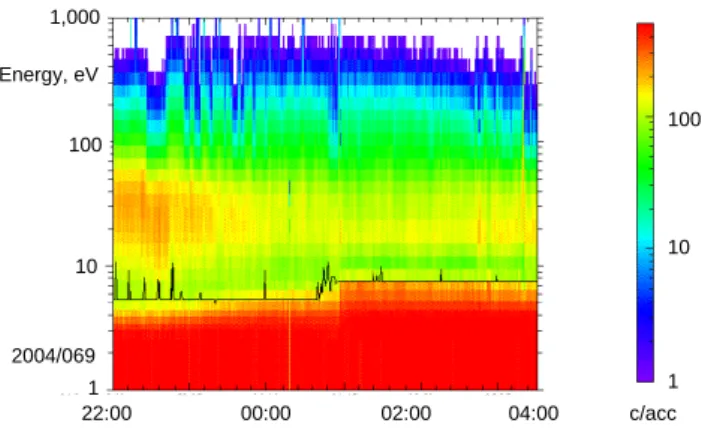
Figure 10. Example of onboard spacecraft potential estimation. Data is from TC-1 on March 09th/10th 2004 in the solar wind.
Fig. 10. Example of onboard spacecraft potential estimation. Data
is from TC-1 on 9/10 March 2004 in the solar wind.
2.7.6 The JPEG compression code
The available data rate for Cluster II PEACE in the stan-dard telemetry mode used most of the time is 1257 bytes/spin (for a 4 s spin) or ∼630 bytes/sensor/spin. By contrast the available data rate for Double Star PEACE is 2236 bytes/spin (again for a 4 s spin) or 2236 bytes/sensor/spin, a factor 3.6 greater than for Cluster. An uncompressed 3-D distribution amounts to 23 040 bytes/sensor/spin, so a compression factor of order 10 is required for Double Star.
A lossless compression scheme (typically achieving com-pression factors of order 2) would be inadequate to transmit the full measured distribution every spin, and does not satisfy the requirement for working within a fixed maximum size for all compressed buffers imposed by the telemetry pack-etisation scheme, because the compression rate in lossless schemes depends on the data complexity which varies with changes in the plasma environment. The publically available “norm JPEG” lossy compression algorithm we have adopted works within the afore-mentioned constraints of very limited storage size for software and data buffers, and limited pro-cessing time. It works with fast Discrete Cosine Transforms, thereby avoiding complex computations and is quick, due to a reduced number of operations.
The general approach for PEACE is to take data as it ar-rives in basic segments and to organize it into sets of two di-mensional “images” of 8×8 pixels. The application of DCTs on such images had been extensively tested and is described in textbooks, for example (Nelson and Gailly, 1995; Pen-nebaker and Mitchell, 1993). In outline, the procedure works as follows:
1. Data in a basic segment is reorganized into a set of 8×8 “images”.
2. The values in the image are rescaled to a maximum of 512.
3. Each image is converted to a DCT coefficient matrix.
4. A weighting factor is applied to the DCT coefficients.
5. The DCT coefficients are bit-streamed into PEACE Sci-ence TM packets ready to be made available to the PDMS, for transmission to Earth and later conversion back to decompressed science data.
The process is discussed in greater detail in the Appendix.
2.7.7 Onboard estimation of spacecraft potential
An estimated value of the spacecraft potential can be com-puted every spin for each of up to 32 energy spectra. The energy spectra used for this consist of the lowest 16 energy bins of 8 consecutive energy sweeps for 4 consecutive polar anodes. The start polar anode and azimuth angle correspond-ing to the first energy sweep used can be commanded from the ground. The algorithm works by searching for an en-ergy bin at which the gradient between neighbouring points in the energy spectra turns positive, starting from the high-est energy bin. Next the search continues towards the low-est energy bin in the spectrum and identifies the bin with the absolute minimum count value as indicating the space-craft potential. The rationale for the algorithm is explained in Johnstone et al. (1997). This algorithm was originally designed for use on Cluster LEEA data (sub-keV electron spectra) and is often quite effective in solar wind and magne-tosheath plasma, although we note that not all energy spectra that a PEACE sensor may measure conform to the underlying assumed form. Also, measured energy spectra can be suffi-ciently spiky that this algorithm may fail on several individ-ual spectra per spin. To provide some measure of reliability, the software is designed to return the mean value from only those spectra where the algorithm is successful, and also cal-culates and returns the variance to give some measure of the statistical significance of the mean value. An example of the onboard spacecraft potential estimation is shown in Fig. 10.
2.7.8 Achieving full instrument energy range coverage
The Double Star PEACE instruments have only a single sen-sor each. Each sensen-sor was part of a pair of Cluster sensen-sors that were designed to be used in combination to cover the full instrument energy range. For any one energy sweep a sensor can only cover about 2/3 of the full set of energies it can operate across.
In order to overcome this limitation, and achieve full en-ergy range coverage from the single sensor, the DPU soft-ware has been adapted such that the sweep preset (which de-fines the energy range sampled) can be alternately switched back and forth between two ground-commanded states, upon reception of the rephased sunpulse (e.g. Figs. 11a and c). This is possible as the DPU triggers reception of the sunpulse on the rising edge of the pulse whereas the sensor triggers on the falling edge, and there is a window of 110 microseconds during which the DPU can sense the sunpulse has occurred and send a command to the sensor to switch the preset. The new preset is used for all sweeps in that spin until it is again switched back to its previous value on arrival of the next sun-pulse. It is, however, imperative that the software does not
A. N. Fazakerley et al.: The Double Star Plasma Electron and Current Experiment 2743
40
Energy,eV 10 10,000 1,000 100Figure 11. (a) illustration of alternating preset mode; (b) illustration of option of returning
only non-overlapping energy data from first sweep in a pair;(c) data plot showing
coverage when operating as in mode outlined in (a).
C
AC
CP
max 66 39 13 66 39 13 66 39 13 66 39 13C
DC
BE
eVC
sum 00 04 08 12 16 20 600 300 0 2004/055Figure 12. JPEG Coefficients
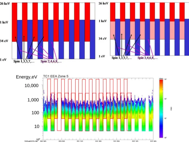
Fig. 11. (a) illustration of alternating preset mode; (b) illustration of option of returning only non-overlapping energy data from first sweep
in a pair; (c) data plot showing coverage when operating as in mode outlined in (a).
exceed the 110 microsecond window or the sweep flyback will have started and the actual sweep energy coverage will not be as intended, at least for the first sweep of the new spin. Using the sensor in this driven loop means that there is a considerable overlap region in the sweep energies measure-ment over two spins (i.e. ∼1/3 of the full set of measurable energies). The software features the option of not telemeter-ing the lower energy part of the data collected durtelemeter-ing the high energy band coverage spins. The data concerned is from the energy range that is sampled both on high energy band cover-age spins and low energy band covercover-age spins (e.g. Fig. 11b), so that during a pair of spins, data from the full instrument energy range will be transmitted. However, the combined data volume sent from the pair of spins is reduced, allowing more efficient use of the telemetry resource and so resulting in fewer “missed spins”.
A further extension of the systematic variation of the sweep preset uses the spacecraft potential determined from the onboard algorithm to determine the lower sweep preset. In this way the lower sweep preset “floats” with the varying spacecraft potential. Both options can be used separately or combined.
2.7.9 Ground software
New EGSE software was developed to take advantage of the modified housekeeping data stream (including the coarse energy-time and polar-time spectrograms) and to enable its operation on a laptop PC. The new software was written in Java, providing the flexibility to run on both SUN worksta-tions and PCs. New software (compared to Cluster) was re-quired in any case to allow communication with the Double Star PDMS EGSE which used a multicast transmission pro-tocol.
New telemetry data processing software was developed to enable the extraction and decompression of Double Star PEACE data from raw telemetry files, and to produce data files in the standard file format used in the PEACE database, with accurate time stamps attached. Thus the data files avail-able to the science user appear essentially identical to Cluster PEACE data files and can be analysed with the same software tools, despite the different data compression method used for Double Star.
2744 A. N. Fazakerley et al.: The Double Star Plasma Electron and Current Experiment
3 Instrument operations
3.1 Commissioning
TC-1 PEACE real-time contact commissioning was carried out on 21–23 January 2004, which coincided with Chinese New Year. The electronic systems were verified, including inter-experiment links, and then the Sweep HVs were cau-tiously exercised. During the following contact opportunity the MCP HVs were gradually brought up to operational lev-els. Finally, scientific operations were demonstrated and var-ious modes exercised. Some unexpected plasma conditions were seen, which later proved to be the consequence of the arrival of an interplanetary coronal mass ejection, and in par-ticular the “sheath” of compressed solar wind ahead of it. All tests were fully successful.
TC-2 PEACE commissioning achieved the same goals, but was carried out a little differently, partly due to the more lim-ited contact opportunities associated with the polar orbit and partly in the light of TC-1 experience with resets in early op-erations (see Sect. 3.3 below). More time was spent in opera-tions designed to cause sensor outgassing; initially by warm-ing the sensor uswarm-ing the heat generated by the low voltage electronics, and later by warming the MCP itself using rela-tively low MCP voltages. These low risk operations, carried out using time tagged commands in between real-time con-tact opportunities were also used to maximise the time spent running the instrument, so as to expose any possible prob-lems while real-time investigations were possible. Again the tests were fully successful.
3.2 Routine operations
In order to protect electronic systems and reduce MCP count-ing unconnected to plasma electrons, we avoid operations in the proton radiation belt altogether, and limit operations in the electron radiation belts by ensuring that PEACE is turned off inside the predicted L=4 L-shell. Penetrating radiation counts are still sometimes seen near L=4 as some of our data figures show, suggesting that if we did operate at lower altitudes, much of the data would be contaminated in the same way. Due to the fact that instrument turn-on takes sev-eral minutes, it is difficult to cover rapid low-altitude passes through the southern cusp and auroral regions on TC-2 while satisfying the constraints mentioned above.
Experience with Cluster has shown that PEACE MCP ag-ing can be reduced by minimisag-ing exposure to photoelec-trons. However on Double Star we have no independent mea-sure of spacecraft potential and therefore need to meamea-sure at least the upper energy component of the photoelectron pop-ulation to enable estimation of the spacecraft potential from PEACE energy spectra. As a compromise we usually raise the minimum measured energy at higher altitudes where the potential is expected to be larger, so as to keep visibility of the spacecraft potential while avoiding the higher fluxes of photoelectrons at the lowest energies. When ASPOC (Ac-tive Spacecraft Potential Control) (Torkar et al., 2005, this
issue) is operating, the potential is generally reduced and so PEACE is required to measure to lower energies in a given region than if ASPOC were off.
These constraints, and others, require fairly complex rou-tine commanding activities which are carried out by the PEACE team.
3.3 Resets
Operations are from time to time disrupted by unplanned ter-minations of science data collection, and hence unwanted data gaps can occur. This applies to TC-1 and TC-2. These events are considered to be generally due to the space envi-ronment affecting the spacecraft subsystems and in particu-lar affecting the spacecraft service signals to PEACE, such as the sun pulse, spin segment clock pulse or the power sup-ply voltage. PEACE is designed to shut down its operations and power supply to the sensor under such circumstances. A trend for these events to occur during and following periods of enhanced radiation belt fluxes led to the suggestion that deep dielectric charging in the harness or possibly other sub-systems could be generating false signals and hence causing PEACE to shutdown. An increase in such events was also noted on each spacecraft after the spacecraft ACS (Attitude Control Subsystem) computers were damaged by radiation. The operational workaround solution that we have adopted is to command regular on cycles. The large number of off-on cycles successfully handled by Cluster PEACE sensors gives us confidence that Double Star PEACE instruments can tolerate this without damage. If an instrument has experi-enced an unplanned turn off, the off-on cycle can restore op-eration and recover the planned data coverage for the rest of the orbit.
3.4 Illustration of data compression
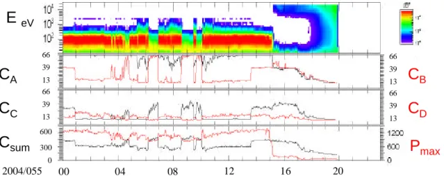
Figure 12 illustrates how the number of correlation coef-ficients returned, varies from image to image in different plasma environments. During this example, PEACE was in MAR sweep mode. The top panel is a simple energy-time spectrogram showing magnetosheath plasma (high fluxes centered on 100 eV) interspersed with solar wind plasma (moderate fluxes at similar, but slightly lower energies) and finally magnetospheric plasma. The bottom panel shows the time history of the maximum count value per basic seg-ment Pmaxin red, which of course reflects the flux intensities
shown in the spectrogram. The same panel also indicates the number of telemetered coefficients per basic segment Csum
in black, which tends to be smaller for more complex energy spectra, and which always falls short of the theoretical max-imum of 768, i.e. if all 64 coefficients were sent for all 12 images in the basic segment. The remaining panels show the breakdown of the number of coefficients CA,B,C,D
transmit-ted for each of 4 types of images, spanning the instrument en-ergy range. These images correspond to four enen-ergy bands, with A the highest energy and D the lowest, as illustrated in Fig. A1, and are for data associated with the first group of
A. N. Fazakerley et al.: The Double Star Plasma Electron and Current Experiment 2745
1
Energy,eV
10
10,000
1,000
100
Figure 11. (a) illustration of alternating preset mode; (b) illustration of option of returning
only non-overlapping energy data from first sweep in a pair;(c) data plot showing
coverage when operating as in mode outlined in (a).
C
AC
CP
max 66 39 13 66 39 13 66 39 13 66 39 13C
DC
BE
eVC
sum 00 04 08 12 16 20 600 300 0 2004/055Figure 12. JPEG Coefficients
Fig. 12. Illustration of the variation with plasma environment of the number of transmitted JPEG coefficients per image.
four polars. All 64 coefficients can easily be returned in the available 10 bytes when there are very few measured counts, as we see for CA, the black trace in the upper panel, which
represents images of type A, at the highest energies. Only when the spacecraft enters the magnetosphere and PEACE sees energetic plasma sheet electrons, do significant fluxes of electrons appear at these energies, and many non-zero coefficients are then generated by the compression code so that the number of coefficients CA, returned in the available
10 bytes per image falls, increasingly as the fluxes increase. At the lowest energies, the energy spectra include a photo-electron population below the spacecraft potential and a mag-netosheath energy population above it. Many fairly large co-efficients are required to describe the form of the resultant spectrum, so that CD the number of coefficients for the type
D images is particularly small. Generally speaking, the en-ergy spectra covered by type B and C images have interme-diate complexity and hence intermeinterme-diate numbers of coeffi-cients are returned. Note that the solar wind distributions are represented with smaller coefficients than the magnetosheath distributions in the images of types B and C, and so more can be transmitted. The jump in most values at 13:40 UT corre-sponds to a mode change and after 13:40 UT is an artefact of the plotting software which averages values from spins with higher and lower energy coverage (before 13:40 UT all spins cover lower energies).
3.5 Ground data processing
As noted in Sect. 2.9, the telemetry data is decompressed and converted to data files of the same form as Cluster PEACE data. In normal operations, the transmitted Double Star PEACE data corresponds to the full resolution 3-D distribu-tion “3DF” data product. In order to support pitch angle de-termination, a support data product called “DFUNIT” is pro-duced using magnetic field data supplied by the magnetome-ter team. Inmagnetome-terpolation is used to generate magnetic field data at higher-than-measured time resolution, so as to produce a vector for each PEACE measurement. Also, the magnetic
field data are put into the coordinate frame which rotates with the PEACE sensor, after which standard PEACE team software can provide pitch angles straightforwardly from the 3DF data.
Since the Double Star PEACE data is provided to science users in the same form as Cluster PEACE data, analysis and plotting software designed for Cluster PEACE can be used quite straightforwardly with Double Star PEACE data. Most data plots in this paper were created with Southwest Data Display and Analysis System (SDDAS) software (e.g. see http://www.sddas.org) developed at the Southwest Research Institute (SwRI). The applicability of this software relies on the use of the underlying IDFS (Instrument Data File System, http://www.idfs.org) approach to data handling, which has been applied to Cluster PEACE by MSSL in co-operation with PEACE Co-Is at SwRI, and extended to Double Star PEACE by MSSL.
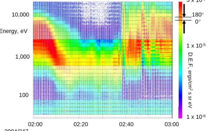
The QPEACE software suite (http://www.space-plasma. qmul.ac.uk/QPEACE) developed by one of the co-authors (SJS) is also able to work from IDFS data files and pro-vides additional methods of examining PEACE data. Fig-ure 13 shows an energy-time spectrogram, in which pitch angles are plotted within each energy band, generated by one of the QPEACE tools (QJAS), which used as input both the PEACE 3DF data and the DFUNIT magnetic field data set described above. Concentrating on 1 to 5 keV electrons, we see almost isotropic distributions initially, bi-directional field aligned beams around 02:35 UT, and strong fluxes at 90◦pitch angle after 02:50 UT.
Moments are calculated from the transmitted velocity dis-tributions, corrected using the estimated spacecraft poten-tial, using “peacemoments” software developed at MSSL. These moments data are the basis for the Prime and Sum-mary Parameter data supplied by MSSL to the Double Star Science Data System. Initial data of this type is produced with crudely estimated spacecraft potential and so may not be as accurate as later iterations; users are encouraged to select events with such data, but are advised to read the
2746 A. N. Fazakerley et al.: The Double Star Plasma Electron and Current Experiment 5 2004/247 100 1,000 10,000 02:00 02:20 02:40 03:00 Energy, eV D.E.F, ergs/cm 2 s sr eV 5 x 10⁻⁵ 1 x 10⁻⁵ 1 x 10⁻⁶ 180° 0°
Figure 13. Example of energy-pitch angle-time plot to demonstrate the effectiveness of ground-based pitch angle production (September 03rd 2004, PEACE data from TC1)
Fig. 13. Example of energy-pitch angle-time plot to demonstrate the
effectiveness of ground-based pitch angle production (3 September 2004, PEACE data from TC-1).
caveats provided with each file and to respect the “rules of the road” when using such data (http://www.cluster.rl.ac.uk/ ddms/rules.htm). The same software can be used to calcu-late the electron contribution to electric current flow in the vicinity of the spacecraft.
3.6 Ground based spacecraft potential determination
The spacecraft potential is a critical parameter for producing accurate moments data from electron distributions. While an onboard potential estimate is often available, it is as-sumed that a more reliable time series could be generated using more complex algorithms during ground analysis of the transmitted data. Techniques are in the process of being evaluated, initially being developed using Cluster PEACE data where comparison with a reference measurement from EFW is possible, and thereafter being applied to Double Star PEACE data. Figure 14 is an example of one method being evaluated, which searches for an expected gradient change in phase space between the photoelectron spectrum and the natural plasma spectrum departure. The estimated potential is shown as black line overlaid on the spectrogram. This is work in progress at the time of writing.
4 Science highlights
Early science studies using PEACE data have focussed on dayside studies with TC-1 and Cluster, simply because that data was available first; some are reported in this journal is-sue, e.g. Dunlop et al. (2005), Marchaudon et al. (2005), and Pu et al. (2005).
Here we briefly describe four additional events to show the potential of the combined Double Star – Cluster dataset to examine large-scale magnetospheric processes. These events will be the subject of deeper study.
41 2004/247 100 1,000 10,000 02:20 02:30 02:40 02:50 Energy, eV D. E. F , ergs /c m 2 s sr eV 5 x 10⁻⁵ 1 x 10⁻⁵ 1 x 10⁻⁶ 180° 0°
Figure 13. Example of energy-pitch angle-time plot to demonstrate the effectiveness of ground-based pitch angle production (September 03rd 2004, PEACE data from TC1)
Energy, eV 10 100 1,000 2004/061 21:18:00 21:18:32 1 Log c/acc 2.4 3 0.3
Figure 14. Example of ground-based estimation of spacecraft potential Fig. 14. Example of ground-based estimation of spacecraft poten-tial.
4.1 Near-midnight apogees: magnetotail
On 3 September 2004, a close magnetic conjunction oc-curred involving both Double Star spacecraft and the Clus-ter flotilla, as illustrated in Fig. 15. TC-1 and ClusClus-ter lie down the tail near the current sheet illustrated in the model magnetosphere (upper plots) and show very similar trends in plasma sheet electron energies (lower plots) from 02:00 UT to about 02:38 UT, although after this time the plasma sheet seen at TC-1 is significantly more disturbed and energetic than that seen further down tail at Cluster. TC-2 is mov-ing northbound, crossmov-ing progressively higher L-shells, and a few minutes before 03:00 UT crosses magnetic field lines that map close to the positions of TC-1 and soon after to Cluster, before entering the northern magnetotail lobe after 03:15 UT. Note that the actual magnetic mapping may differ in some details from the illustrative model shown here, but is expected to be reasonably representative.
At about 02:38 UT, a significant increase in both the plasma sheet electron energy and differential energy flux is seen at TC-1. At about the same time, the character of the plasma sheet seen at TC-2 also changes, and beams of en-ergetic (∼10 keV) electrons are seen by the Cluster quartet. Just prior to these events, at 02:36 UT, both Cluster and TC-1 see enhanced bi-directional electron fluxes at plasma sheet energies (∼keV) (not shown). Preliminary magnetometer data from TC-1 show a reduction in Bx, together with an
increase in Bz, suggesting that a dipolarisation of the
mag-netic field occurred near the location of TC-1. Similar sig-natures are seen at the four Cluster spacecraft, consistent with an Earthward moving dipolarisation front. Magnetic field deflections at TC-2 are suggestive of a field aligned current consistent with a substorm current wedge. The dis-turbance seems to propagate from Cluster to TC-1 to TC-2. Unfortunately, TC-2 electron pitch angle data are not avail-able at the time of writing. This interval is being actively studied, to investigate how the plasmasheet electrons at TC-1 and TC-2 have become energised, and what is the exact sequence of events along the magnetotail from Cluster to the
A. N. Fazakerley et al.: The Double Star Plasma Electron and Current Experiment 2747
2
C1 TC1 TC2 TC2 TC1 C1 C1 TC1 TC2 03 September 2004 02:00 – 04:00 UT Positions at 03:00 UTFigure 15: above, September 03
rd2004, orbital positions and OVT model magnetosphere
in GSM, views from –X, Y and Z; below, PEACE data from TC1, TC2 and C4. X-axis
labels show UT time, L-shell, MLT and invariant latitude.
Fig. 15. Above, 3 September 2004, orbital positions and OVT model magnetosphere in GSM, views from −X, Y and Z; below, PEACE data