PFC/RR-87-20
DOE/ET-51013-242
UC20 A, F, G
Current-Drive on the Versator I Tokamak
with a Slotted-Waveguide Fast-Wave Coupler
Colborn, J.A.
Plasma Fusion Center
Massachusetts Institute of Technology
Cambridge, MA 02139
November 1987
This work was supported by the U. S. Department of Energy Contract No.
DE-AC02-78ET51013. Reproduction, translation, publication, use and disposal, in whole or in part
by or for the United States government is permitted.
CURRENT-DRIVE ON THE VERSATOR-II TOKAMAK
WITH A
SLOTTED-WAVEGUIDE FAST-WAVE COUPLER
by
JEFFREY ALAN COLBORN
B.S., University of California, Berkeley, 1983
Submitted to the
Department of Electrical Engineering and Computer Science
in Partial Fulfillment of the Requirements
for the Degree of
MASTER OF SCIENCE
at the
MASSACHUSETTS INSTITUTE OF TECHNOLOGY
August 31, 1987
o Massachusetts Institute of Technology, 1987
Signature of Author
Department of Electrical Engineering
and Computer Science
August 31, 1987
Certified by
Professor Ronald R. Parker
Thesis Supervisor
Accepted by
Professor Arthur C. Smith
Chairman, Departmental Committee
7
al
CURRENT-DRIVE ON THE VERSATOR-I TOKAMAK
WITH A
SLOTTED-WAVEGUIDE FAST-WAVE COUPLER
by
JEFFREY ALAN COLBORN
Submitted to the Department of Electrical Engineering and Computer Science
in September 1987 in Partial Fu1fillment of the Requirements
for the Degree of Master of Science
ABSTRACT
A slotted-waveguide fast-wave coupler has been constructed, without
dielectric, and used to drive current on the Versator-II tokamak. Up to
35 kW of net microwave power at 2.45 GHz has been radiated into
plas-mas with 2 x
101
2cm-
3iWe
5
1.2 x 101
3cm-
3and
Bt,.
s
1.0 T. The
launched spectrum had a peak near N
11
=
-2.0 and a larger peak near
N
11=
0.7. Radiating efficiency of the antenna was roughly independent of
antenna position except when the antenna was at least 0.2 cm outside the
limiter, in which case the radiating efficiency slightly improved as the
an-tenna was moved farther outside. When the coupler was inside the limiter,
radiating efficiency improved moderately with increased iie. Current-drive
efficiency was comparable to that of the slow wave and was not affected
when the antenna spectrum was reversed; however, no current was driven
for
iie<
2 x 101
2cm-3. These results indicate the
fast
wave was launched,
but a substantial part of the power may have been mode-converted to the
slow wave, possibly via a downshift in N
11, and these slow waves may have
been responsible for most of the driven current. Relevant theory for waves
in plasma, current-drive efficiency, and coupling of the slotted-waveguide is
discussed, the antenna design method is explained, and future work,
includ-ing the construction of a much-improved probe-fed antenna, is described.
Thesis Supervisor: Dr. Ronald R. Parker
Titles: Professor of Electrical Engineering
ACKNOWLEDGEMENTS
This work was performed at the MIT Plasma Fusion Center and
Re-search Laboratory of Electronics and was supported by U. S. DOE Contract
NO. DE-AC02-78ET51013 and the Magnetic Fusion Energy Technology
Fel-lowship Program administered by Oak Ridge Associated Universities for the
U. S. DOE.
I thank Professor Ron Parker for his academic support and for the
original idea of a slotted-waveguide fast-wave coupler.
I thank Professor Miklos Porkolab and Dr. Stanley Luckhardt for
al-lowing me to perform my experiment on Versitor-II, and I thank Dr.
Luck-hardt and Dr. Kwo-In Chen for expertly operating the tokamak during my
experiment, and for their general support.
Fellow graduate students Joel Villasefior and Jared Squire deserve
thanks for troubleshooting the rf system and providing hard X-ray data,
respectively, as do Ed Fitzgerald and Jack Nickerson for their invaluable
technical support.
CONTENTS
Abstract . . . . .
Acknowledgements
. . . .
List of Figures . . . .
Background and Theory of Current Drive . . . .
Magnetic Fusion and Current Drive
. . . .
Cold Plasma Wave Theory
. . . .
Simple Picture of Current-Drive Efficiency
. . . .
Fisch-Karney-Boozer Theory of Current-Drive . . . .
The History of Lower-Hybrid Current-Drive Experimentation
1.6
Motivation for Fast-Wave Current-Drive
. . .
Chapter 2 The Slotted Waveguide . . . .
2.1 Motivation
. . . .
2.2 Design Theory for Radiating into Free-Space
2.2.1
Single-Slot Conductance
. . . .
2.2.2 Arrays . . . .
2.3
Spectrum and Coupling . . . .
Chapter 3
3.1
3.2
Chapter 4
4.1
4.2
4.3
4.4
Chapter 5
References
Experimental Apparatus . . . .Apparatus for Versator-II Experiment . . . .
Test-Bench Apparatus . . . . Experimental RPesults . . . . Current-Drive Results . . . . Coupling Results . . . . Test-Bench Results . . . . Performance of Components . . . . Conclusions and Future Work . . . .
..
2
..
3
..
5
..
7
..
7
..
8
. . . 18
. . . 19
. . . 26
. . . 29
. . . 36
. . . 36
. . . 40. . . 40
. . . 48. . . 56
. . . 74
. . . 74
. . . 77
. . . 81
. . . 81
. . . 85
. . . 92
. . . 94
. . . 98
100
Chapter 11.1
1.21.3
1.4
1.5FIGURES
Schematic diagram of a tokamak
. . . .
The transformer circuit of a tokamak
. . . .. . . . .
Coordinate system for accessibility calculation in slab geometry. .
Q
versus N for accessibility. . . . . . . . .Figure 1:
Figure 2:
Figure 3:
Figure 4:
Figure 5:
Figure 6:
Figure 7:
Figure 8:
Figure 9a:
Figure 9b:
Figure 10:
Figure 11:
Figure 12:
Figure 13:
Figure 14:
Figure 15:
Figure 16:
Figure 17:
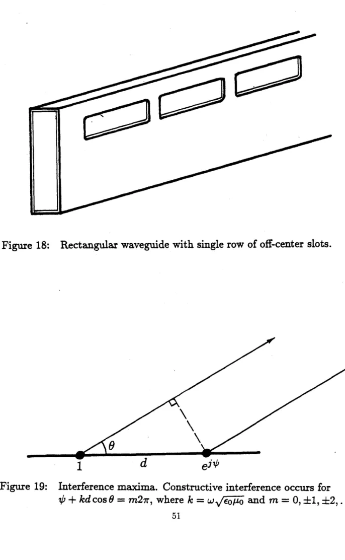
Figure 18:
Figure 19:
Figure 20:
Figure 21:
Figure 22:
Figure 23:
Figure 24:
Figure 25:
Figure 26:
Figure 27:
esence of stronma on PLT.
fast and slow
Loop coupler . . . . . . . . .
The slotted-waveguide coupler used in Versator-II. . . . The antenna in Versator-II . . . . .. . . . ..
Cylindrical waveguide of arbitrary cross-section... Rectangular waveguide with probe-fed slots. . . . . Resistance of longitudinal slot. . . . . Admittance of longitudinal slot versus frequency. . . . . Rectangular waveguide with single row of off-center slots. Interference maxima. . . . . Interference maxima for non-probe-fed slots. . . . . .
Interference maxima for probe-fed slots .. . . . .
Design of probe-fed antenna radiating at N11 = -1.2. . .
Spectrum of one slot 2 cm x 1 cm. . . . . Spectrum of probe-fed slot array. . . . -. . . ..
Interference plot for the antenna used on Versator-II. . . Spectrum of the antenna used on Versator-II. . . . . .
S. . .
9
.
. . .
10
.
. . .
13
. . . .
13
Plot of N_ versus density . . . .
.. .
Distribution function for electrons in the pr
Plot of relativistic current-drive efficiency.
Current versus time for a "flattopping" plas Plot of accessibility condition. . . . . . Plot showing regions of propagation for theWaveguide grill . . . .
. . .
.
Spectrum of probe-fed antenna design radiating at N11 = -2.. . . 62
. . . 16
grf. . . . 24
. . . 24
. . . 28
. . . 31
waves. . . . . 31
. . . 37
. . . 37
. . . 38
. . . 39
. . . 41
. . . 41
. . . 49. . . 50
51
. . . ... . . 51
. . . 54
. . . 55
57
. . . 58
. . . 59
. . . 60
. . . 61
Figure 28:
Figure 29:
Figure 30:
Figure 31:
Figure 32:
Figure 33:
Figure 34:
Figure 35:
Figure 36:
Figure 37:
Figure 38:
Figure 39:
Figure 40:
Figure 41a:
Figure 41b:
Figure 42:
Figure 43:
Figure 44:
Figure 45:
Density versus distance from the antenna for coupling calculation.
Coordinate system for the coupling problem.
. . . .
Transmission-line model for the antenna. . . . .
Contour for inverse transforming the wave fields.
. . . . .
Schematic diagram of the rf power supply. . . . . Schematic diagram of the low-power rf circuitry. . . . . Test-bench apparatus. . . . . . . . .
Technique for measuring the single-slot conductance... Definition of "forward" and "reverse" spectra. . . . . Data for forward shot. . . . .
Data for reverse shot .. . . . .
Hard X-ray data .. . . . .
Equal current-drive efficiencies for forward and reverse spectra. Radiating efficiency versus ARP for forward spectrum. . . .
Radiating efficiency versus ARP for reverse spectrum. . . .
Radiating efficiency versus density. . . . . Schematic diagram showing edge-density measurement. . . .
Far-field pattern and polarization data. . . . . Mica vacuum window destroyed by rf. . . . .
. . . 64
. . . 64
. . . 68
. . . 68
. . . 75
. . . 76
. . . 79
. . . 80
. . . 82
. . . 83
. . . 84
. . . 86
. . . . 86
. . . 89
. . . 89
. . . 90
. . . 91
. . . 95
. . . 96
1 BACKGROUND AND THEORY OF CURRENT-DRIVE
1.1 Magnetic Fusion and Current-Drive
Nuclear Fusion is the workhorse of the Universe. It supplies energy to the sun and stars, making them shine and preventing their collapse. In an effort to harness this energy source, physicists and engineers have been developing fusion since the early 1950s. The easiest fusion reaction to accomplish is that of deuterium nuclei (or ions), which consist of one proton and one neutron, with tritium nuclei, which consist of one proton and two neutrons:
D+ + T+ -
He2+ + n + 17.6 MeV
where He2+ is a helium nucleus, n is a neutron, 17.6 MeV is the energy released per reaction, and the superscripts indicate charge. This reaction requires some energy input. For the nuclei to fuse, the Coulomb repulsive force must be overcome and the ions brought together to within - 10-15 meters. At this distance the nuclear
strong force, an attractive force, can overcome the Coulomb repulsion and pull the nuclei together.
In magnetic fusion, the repulsive force is overcome by confining the ions by a magnetic field and heating them to extremely high temperatures, forming a plasma. The quality of a fusion plasma is measured by its ion temperature and Lawson parameter,['] which is the product of the plasma density n, and energy confinement time r. The energy confinement time is defined in equilibrium as the total plasma energy divided by the total power input to (or loss from) the plasma. For an economically feasible fusion reactor, the Lawson parameter must be greater than about 10O1 cm 3-s, and the ion temperature must be about 200,000,000 K.
The most successful magnetic confinement scheme to date has been the toka-mak
(see
Figure 1), which was invented by Russian physicists2] in the 1950s and is continually being refined and improved. As shown in Figure 1, the tokamak has two components of the magnetic field-a toroidal component directed the long way around the torus, and a poloidal component circulating the short way around. These components add to give field lines that twist helically around the tokamak. Both field components are needed for the equilibrium and stability of the plasma.The toroidal magnetic field is produced by a set of coils that are outside the plasma, as shown in Figure 1. The poloidal field is produced by a toroidal plasma current (often several megaamps in contemporary tokamaks). Traditionally, this current has been generated via induction, the plasma being a one-turn secondary coil of a transformer. This current cannot be steady-state, because it is proportional to the time-rate-of-change of the poloidal magnetic flux linked by the plasma (see Figure 2). That is, the tokamak must be pulsed and the transformer recocked between pulses. Pulsing a reactor fatigues its structure and lowers its average power output. If current could be driven noninductively in plasmas, a steady-state reactor could be realized. Methods have been proposed for driving current using radiofrequency electromagnetic waves (rf), relativistic electron beams, phased injection of frozen hydrogen pellets, and oscillating magnetic fields. 3] [4] [5] [6] [7] In
this thesis, I report my investigations on driving current using rf to excite the "fast lower-hybrid wave" in the Versator-II tokamak.
1.2 Cold-Plasma Wave Theory
The polarization and dispersion of the lower-hybrid fast- and slow-waves can be obtained for a cold plasma from Maxwell's equations and the fluid or kinetic
Icoil
Bo
Plasma
Magnetic-field
lines
Figure 1:
IP
External
toroidal-field
coil
Schematic Diagram of a Tokamak. The toroidal-field coils are
spaced uniformly around the torus; only one is shown for clarity.
L
OB
0t
U - U ~N
-
m ~
im
mu ~
Figure 2: The transformer circuit of a tokamak.
v(t)
equations. The cold plasma approximation accurately describes the wave dispersion in the current-drive regime because in this regime there are no resonance layers
(k
1 -* oo) in the plasma. Landau damping, the mechanism by which lower-hybridwaves drive current, is a very important thermal effect that does not affect wave dispersion.
Starting with Maxwell's equations, assuming waves varying as exp(zk - r-iwt), using the WKB approximation (jkI
>>
I9/8rl),
and assuming a linear, dispersive medium, we obtain the wave equation:kx(kxE) + -K-E = 0 (1)
C2
where the equation has been transformed in time and space, k is the wave vector,
E is the wave electric-field, o is the wave frequency, c is the speed of light, and K
is the dielectric tensor, incorporating free-current effects. It is defined as follows:
K-E = E +
-J
(2)WE0
where J = njoZjevj1 is the plasma current (summed over species), no is the
zeroth-order density, Z is the charge state of the species, e is the magnitude of the charge of the electron, and v, is the first-order (wave-induced) particle velocity. Applying cold-plasma theory, i. e. , using the fluid equations or the reduced kinetic equations, the dielectric tensor for B = iB(r) becomes
_ KXX K7 0
K = -Kxy Kxx 0 (3)
where 22 KXX =O 1 - wA2 - 2 LL2 - W2-' (4) .(4 w2 - 2 ce C pe c (Z W2 2
Kzz = I -i
-
,(6)
Wpi = nj e2Z?/m Eo is the plasma frequency of the jth species
(e.
g. electrons orhydrogen ions), and woc = ZjeB/mj is the cyclotron frequency of the jth species. For the plasma interior (i. e. , not in the coupling region), we may assume, without loss of generality, the situation shown in Figure 3, so that NI, = ckIl
/w
=(ck/w)
cos 0 and N1 = ckj/w
=(ck/w)
sin 0. Substituting into the wave equation, we getKxx - N
2K.,y
NI IN-L
N1 N /1E
-KxI
KE - N2E
0.(7)
NI N
0
K.. - NI
Ez
The dispersion relation is obtained by setting the determinant of this system of equations to zero. This yields the following quadratic equation for NI:
KxzNI + NI [(Kxz +
Kzz)N -(K +
K +K.,Kz)]
(8)
+ Kzz[(N 2 -
Kxx)
2+ K
2,]
Applying the lower-hybrid approximating condition, u)«w< 2 W ,< e yields the following for the dielectric tensor elements:
2 2
+ -
k
k
kz
z
EE
I Ez
y
E
XEy
Figure 3: Coordinate system for accessibility calculation in slab geometry.
no propagation
A=
B
(K+y7Kz
propagationA
B
non-propagating complex rootsQ
versus
V2for accessibility.
IQ
Figure 4:
6MO100
I
j
--i 2
Kpe
(10)
2
Wpce
Kzz
1 -(11)Making the further approximations that Kzz
>
K., and IKj>
(Ni -Kr)yields the following dispersion relation[8l
2K K2
2K
N
2 = - _+-K
Kzz
-- ( Kzz +
KX2/Kzz)2] N
-
([KN,
-
K ,/K
2 2 )2](12)
Calling the quantity under the large radical
Q,
we get the situation shown in Figure 4. Requiring NI to be positive yields the following condition on N11:[81-2
NW2
> Wpi+
+cwce)
.(13)
v/ococe cie U.2
Waves are evanescent in regions of the plasma for which the above inequality is violated. Making an equality out of it and solving for wi gives the density at which the fast and slow wave roots coalesce, i. e. , the mode-conversion layer. Here an inward-propagating fast wave is converted to an outward-propagating slow wave:[']
=
NllY ±
1-+.N2(y2_1)
(14)
where Y2 2
/w
0 and 0s=
Wcewci. Curves showing the accessibility conditionaccessibility curve looks like the left half of Figure 5a. For Y2 < 1 as shown in
Figure 5, a local maxima f/Equation 13 exists at w'/2 y 2/(1 _ y 2
)
whereN
=(15)
V/1 - Y2
Propagation to higher densities reqpires no further increase in N11, as can be seen
from Figure 9.
To determine the fast-waive cutoff properly, all three components of the wave-vector, N,, N,, and N,, must be explicitly included. This is necessary for the following reason. For the accessibility calculation, the region of interest is near the mode-conversion layer, irnthe interior of the plasma. Therefore we may use the WKB approximation and asshme theescale lengths for density and field gradients are small compared to a wavelength so w6 may treat the plasma as locally homogeneous. This enables us to rotate th6ocoordinate system so that k and BO are always in the x-z plane and the problem is reducid to two dimensions so k = ki
+
ki 2. For the coupling problem, however, the plasma boundary is an inherent inhomogeneity. The direction of BO and the normal to the plasma surface are innate to the problem. The wave-vector can have.' omponente in each of these directions and perpendicular to both. Hence, three components are required.The wave equation becomes
Kx - N
2-
N2K, + NyNx
N
2N.
E.
Ky. + N.Ny
K,!, - Ni - N.
NN
)
E
0.
(16)
N.Nz
NiNz
Kzz - NX
N
)
Ez
The dispersion relatidn is obtainedms before by setting the determinant of this system of equations to zero. The cokl plasma approximation yields Kzr = KzV=
Kxz = Kyz = 0, K,, = Kx,
andId., = -K,,.
The lower-hybrid approximating condition gives simplified dielectricatensor elements as before, and the fast- and2)s
F
N1I1
4a N1 W40
--
22
-~77~!or
C)
S
FI
I
-I-
(A);t
.-Y <I
andN <
11-Ya
4'
r
NZ =
I
and Y2< (A 2.N
> andY
2<
a wiFigure 5:
Plot of
N'
versus density
(w
;/w
2),
showing the slow
and fast roots of the lower-hybrid dispersion relation.
The slow- and fast-wave cutoffs are
2,/W2 and
w2
/w
2.
The lower-hybrid resonance is at w,/W and the points
where the slow and fast waves meet are
w
_/I2 and
LL+/2 2
(from reference [10]).
W~
W
b)
SI
Fs
|
FI
'U W-WorWr
a)
F Nslow-wave cutoff conditions can quickly be obtained from the resulting equation. For cutoff, N, - 0, and we obtain the following:
K..(K..
-
N2
-
N2)(K.
- N)
+ K..K,
=0.
(17)This equation has two solutions. The slow-wave cutoff density is given by K,, = 0, so that the slow-wave is evanescent at electron densities below nitof= w2meo/e2. The fast-wave cutoff is given by
(Kzz - Nz - Nv2)(Kzx - Nz2) + KZ= 0, (18)
giving an approximate cutoff density of
ncutoff = (mefo/e2)wwc,
(1
-
N
-N
2)(1
-Ne).
(19)
For typical Versator-II parameters of We,/27r
= 28 GHz, w/27r
=2.45 GHz, N
2= 4,
N = 0, this gives nf toff ~ -2 3 4ncUtoff, making the fast-wave more difficult to
1.3 Simple Picture of Current-Drive Efficiency
The current-drive efficiency, J/Pd, is the toroidal current density divided by
the wave power dissipated per unit volume. An approximate expression for it can be obtained by balancing the rf power required to diffuse electrons outward in velocity-space with the power lost due to collisions with the bulk plasma.["]
Consider the resonant interaction of waves with phase velocity v,
>
Vte and electrons with velocity v, parallel to the confining magnetic field, where vt, =2Te/me is the electron thermal speed. The current density generated from
push-ing the electrons in velocity-space with the rf is given by
J = n, ev
(20)
where n, is the density of the resonant electrons. These electrons are slowed by Coulomb collisions with the bulk plasma, which exerts a drag force given by the following:
Fd = nmev,-2
(21)
where log A is the Coulomb logarithm, n is the bulk density, and Wpe = Vnee2/me Eo
is the electron plasma frequency. Note that Fd is proportional to v, 2. For steady-state current-drive, the rf power density is equal to the power lost to the bulk via drag:
n, LA 4 M, log A
Pd
= Fd . V - P(22)
The current-drive efficiency is the driven current divided by the dissipated power density:
J
=47rne
Pd P U;4 me log
A
Volume averaging yields the following figure of merit for steady-state current-drive in a tokamak:
ii(1020
m-3)I(kA)R(m) 2
Pr(kW)
=
constant
(24)
where W is the line-averaged electron density, I is the driven toroidal plasma current, and R is the major radius.
The figure of merit is proportional to vp, which shows higher phase-velocity waves drive current more efficiently. This is because they resonate with faster, less
collisional electrons.
1.4 Fisch-Karney-Boozer Theory of Current Drive
To gain a more realistic qualitative picture of how current-drive works, and to obtain accurate quantitative predictions of current-drive efficiency, kinetic theory must be used. The interaction of the waves and the electron distribution function must be examined, taking into account two-dimensional effects.
Following the analysis of Fisch and Boozer,[12] the current-drive efficiency J/Pd
may be calculated using an "impulse response" method, where J is the driven current density and Pd is the power dissipated per unit volume.
Consider the displacement in velocity space of a small number of electrons
5f
from velocity v, to v2. The energy required for this displacement is
AE = (E2 - E1
)bf,
(25)where El =
jmev2
and E2 = Imev2. Recall from the previous section that thecollisional drag on an electron is dependent on its velocity. Assigning a velocity decay rate vi(v) to each velocity vi gives the following transient current:
J(t)
= -ebf [v 1l2e~"t - vlle-"a] , (26)where the 11 subscript indicates the component of vi parallel to the confining mag-netic field. The first term on the right results from the new electron at velocity v2,
and the second term results from the missing electron at v1. These currents decay
at different rates v, and v2, which depend only on v, and v2.[12]
The average of J(t) over a time At that is large compared to 1/vi and 1/v2 is
defined as J:
JJ(t)dt
=
(
-
(27)
where J can be interpreted as the current generated in a time At by an amount of energy AE. Substituting from Equation 25 for 8f and identifying AE/At as Pd yields the following:
- = -e Vi1/ I2/V2) (28)
Pd
El - E
Taking the limit as v2 -+ v1 yields[12]
J
-es-V,(vj/v) (29)where
s
is the unit vector (in velocity space) in the direction of Av, V, is the gradient operator in velocity space, and the subscripts have been dropped.This equation shows that the current-drive efficiency depends on the velocity of the electrons absorbing the power, and on the direction in velocity space in which these electrons are accelerated. This can be seen by taking the limit vi -+ v2 of
Equation 27:1 1
J = -e--V, ( (30)
'&t
V(V)
where Av = v2 - vi and v =
lvi.
Differentiating,J -eV At (V + V11 (31)
;2
The first term represents the contribution to the current via direct parallel momen-tum transfer from the rf to the electrons and is proportional to the z-component of Av. The second term, present even if no parallel momentum is imparted to the electrons, is due to the velocity dependence of the collision frequency. If electrons traveling in one toroidal direction are preferentially heated, even if this heating is purely perpendicular, they will become less collisional, resulting in an asymmetric resistivity and a net toroidal current.
Now Av is related to the characteristics of the rf wave that produces it. Energy and momentum are absorbed by the electron when it is in "resonance" with the wave, that is, when the Doppler-shifted wave frequency (as seen by the electron streaming parallel to the confining magnetic field) is an integer multiple of the
cyclotron frequency:
where n = 0, ±1, ±2,.... The parallel velocity at which an electron will strongly absorb energy from the wave is then
V11 = k . (33)
For waves in the lower-hybrid range of frequencies (LHRF), such as those radiated by
the present antenna, w < uce and resonance occurs for n = 0, yielding v11 = L/kg =
Vphase. Because we want electrons with a particular sign of v11 to be preferentially
heated, this shows that in the LHRF, we must launch rf waves with a phase velocity in a particular parallel direction.
The basic idea of current drive through parallel momentum transfer can best be understood by considering the original paper on the subject by Fisch.[] The one-dimensional treatment presented there shows how the first term in Equation 31 contributes to the current-drive efficiency of a broad spectrum of waves interacting with a distribution of electrons.
In the parallel direction, the rf diffuses electrons outward in velocity space, competing with the collisional relaxation of the plasma, which attempts to restore itself to a Maxwellian. The effect of the rf is encapsulated into a quasilinear diffu-sion coefficient, DQL, which enters the one-dimendiffu-sional Fokker-Planck equation as
follows:
[-
-DQL(vIi)
+ --
(34)
9t v I of OfOc
where 2 is the Fokker-Planck collision operator, which includes Coulomb scat-tering in both the parallel and perpendicular directions. Integrating Equation 34
over the perpendicular direction, assuming f is Maxwellian in this direction, yields the following equation for high velocity electrons:
Of
_D(w)af
a
1
f
f(
a-r
aW O1W
&W
W3
OV
W2
where w = V11/Vth, r = vot, Vo = v'w, 4, ln
A/27rnevg,
and D(w)DQLIVOVth.
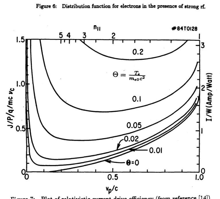
With strong rf, D(w) is very large for w, < w < W2 and zero otherwise, and the steady-state solution to Equation 35 is approximately flat for w1 < w < W 2 and roughly Maxwellian outside this region (see Figure 6).
The height of the plateau is found by evaluating the bulk Maxwellian at w =w:
f(w)
f(wi) = e_,. (36)The current carried by the resonant electrons with w, < w < w 2 is given by
J
=
f
neeweVthf(wi) d
e - 2 w 2 2i
(37)
=ne
eVthe' W WIn the steady-state, the power absorbed by the resonant electrons from the rf is
equal to the power absorbed by the bulk from the resonant electrons via Coulomb
collisions. This dissipated power is given by the following:
Ix
1k
'Wi1
W2
w
Figure 6: Distribution function for electrons in the presence of strong rf.
5
4
3
nil
2
#84T0128
0.5
1.
3
E
10
0
Figure 7:
Vp/C
Plot of relativistic current-drive efficiency (from reference [14]).
f(w)
I.
E
a.
0.2
E
=
T.
~
meoc20
0.1
50.05
.2-0.01
0=0
n - -
'
'--
'_
'-
'
'
0.
"0
!I
I
where v., = v'(v'3/V2)(2
+
Z1) in the limit vII/vth>
1, which is a goodapproxi-mation for the high velocity resonant electronsE31 and Zi is the charge state of the
background ions. Evaluating the above integral yields
Pd = nemVthv' (2 + Zj) ln(w2/Wi). (39)
The total driven current over the total input power is given by
I
_(J)
-- = (40)
P
2,rR(Pd)
where
()
indicates an average over the plasma cross-section, and toroidal symmetryis assumed. The current-drive figure of merit i is obtained by combining Equations
37, 39 and 40, giving
_ (10 20m-3)I(kA)R(m)
P(kW)
(41)-0.0054T(keV)
Wn\2 f(2 + Zj)ln(W2/Wi)
Note that i is proportional to velocity squared, as given in the simple picture of
section 1.3.
Expressed in terms of the N11 of the rf wave spectrum, the figure of merit is
1.4 1/N2 - 1/N 2112
1.41 (42)
2 +Zi 21n(NilI /N112) (2
where N112 < NII < N111. This shows that waves with high parallel phase velocity
Recall that an asymmetric resistivity is produced by the perpendicular-velocity-space structure of the interaction of the rf with the plasma. This makes current drive
by cyclotron damping possible. However, this effect is not important for current
drive by lower-hybrid waves, which diffuse particles only in the vil-direction.
An additional effect neglected in Equation 35 is the two-dimensional structure of the collision operator. When this structure is retained, the calculated current-drive efficiency is improved by a factor of two.[12] This is because when electrons are pitch-angle scattered out of the resonance region by the bulk, resulting in a loss of parallel momentum, they gain (on the average) perpendicular energy. This decreases their collisionality relative to what one would expect if the increase in perpendicular energy were ignored. Because these electrons are on the average traveling in the same direction as before they were scattered, the calculated current-drive efficiency is higher than one would expect taking into account only the parallel dynamics.
A fully relativistic calculation of the current-drive efficiency of low-N11
lower-hybrid waves is given by Karney and Fisch.["] They find that two relativistic effects set an upper limit on the efficiency. First, the relativistic electrons slow down faster because they are heavier. Second, the current carried by the electrons is proportional to their velocity, which approaches a constant (equal to the speed of light) as momentum is imparted to them and they become heavier. Each of these effects reduces the efficiency by a factor of -y, so combined they reduce i by a factor of Y2 , 2, where p is momentum, cancelling the nonrelativistic v2 dependence and
forcing
i
to approach a constant at high velocities. This dependence is shown inFigure 7.[1"1
1.5 The History of Lower-Hybrid Current Drive Experimentation
Soon after Fisch's paper[N] was published, slow-wave current-drive results were reported on the JFT-2 tokamak in Japan["5] and the Versator-II tokamak at MIT.[6]
The slow wave was used in these experiments because it is easy to launch, and because it has a higher Landau damping rate, making it more effective in driving current in the relatively small, cold, tenuous plasmas of these tokamaks. The current was sustained mostly by the Ohmic Heating (OH) transformer and current drive of - 15 kA was inferred by comparing the currents and loop voltages of plasma
shots with and without rf. On Versator, the increased current was not due to a reduction in plasma resistivity caused by the rf, because the electron temperature (as measured by Thomson scattering) went down during the rf pulse, thereby increasing the resistance.["] Also, the current-drive efficiency went abruptly to zero above a certain critical density, called the "density limit." This was unexpected because Fisch's theory predicts the efficiency to scale as ii,;. On the Versator 800 MHz experiment, this density limit was about 6 x 1012 cm-3, for which the lower-hybrid
frequency ;LH/27r is about 400 MHz.
Current was "flattopped" for the first time on the PLT tokamak at Princetonj1']
where a fully rf-driven current of 165 kA was maintained for 3.5 s with the loop voltage near zero. The OH transformer primary current was clamped after plasma start-up, and the subsequent LIR decay of the plasma current was fully arrested
by the rf, so that a steady-state current was maintained (see Figure 8). A
flattop-ping current-drive efficiency
i
=iIR/Prf
- 0.1 was attained, in reasonably good agreement with Fisch's theory.[N] A density limit was observed on this experiment of 8 x 10 12cm-3, for which WLH/ 27r ~ 600 MHz.Current was first driven at high densities (- 10 1 4cm-3) on the Alcator tokamak
at MIT. Up to 200 kA was maintained by 1.1 MW of 4.6 GHz slow waves launched by a 4 x 4 phased array of waveguides. Efficiency was measured over a wide density range and found to agree well with the Fisch[3] theory;
i
~z 0.12 was attained with B0 = 10 T and ij ~ 0.08 for Bo = 8 T.[181 Since these results were obtained, currenthas been driven by slow waves on other tokamaks throughout the world.
Mayberry, et. al. ,[19] showed that the density limit is a function of the source frequency by driving current on Versator-II with a 2.45 GHz source at densities
RF On 2 - \RFOff 130 kW RF Power (b)-No RF , RF Off,,-,. I O -- - A" O
Figure 8:
(a)-(d) Characteristics of deuterium discharges in
the PLT tokamak with and without 130 kW of rf,
B
0=
3.1 T. (e) A long-pulse discharge with 70 kW of rf,
B
0=
2.3 T (from reference [17]).
0 0.5 1.0 TI ME (sec) 3 (,) RF On \No RF 0 1 2 3 4 TIME (sec) 0.5 0 5above 1 x 1013cm-3 with the same toroidal magnetic field as for the 800
MHz
experiments. A flattopping current-drive efficiency
i
= 0.0072 was attained. Thisefficiency is considerably lower than that of the PLT and Alcator experiments. This could be due to poorer confinement of the fast current-carrying electrons, poorer accessibility of low-N11 waves, or the larger "spectral gap." The first two are caused
by the lower toroidal magnetic field on Versator, and the third by the lower electron
temperature.
Little experimental data has been obtained on fast-wave current-drive. Exper-iments have been performed on PLT at 800 MHz,[2 0] JIPPT-IIU at 40 MHzL21] and
800MHz,[2 2
) JFT2-M at 200 MHz,[23] and ACT-I at 18 MHz.[2
1] In the 800 MHz
experiments, both fast and slow waves could propagate in the plasma. Antenna coupling characteristics indicated that the fast wave was being launched, but the current-drive efficiency and "density limit" were identical to those of the slow wave. Although some authors[22] claim to have driven current with the fast wave, it is probable that in both the 800 MHz experiments, fast waves were lauched, but much of the power in the waves was subsequently mode-converted to the slow wave via a toroidal N -shift, and the slow wave (which interacts with electrons much more strongly) was driving most of the current.
1.6 Motivation for Fast-Wave Current-Drive
The primary motivation for studying the fast-wave is that it is more capable than the slow wave of penetrating to the core of a hot, dense, reactor-grade plasma and driving current efficiently there. This is because low N11 waves, which drive
This can be seen in the following way.[25] Recall from section 1.2 the accessibility condition for waves in the LHRF:
2 2
N : > o
+
1+ 1 -(43)
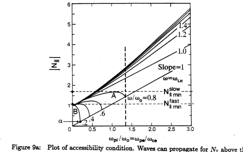
where wO = is the mean gyrofrequency and w is the source frequency. Waves can propagate anywhere in the plasma where this inequality is satisfied. Figure 9a is a plot of INiimin| as a function of wLi/wo for various values of w/wo, where Nimin is obtained by making the above inequality an equality. Propagation can occur above a given curve for the corresponding w/wo, as shown in Figure 9b.
I refer to these curves as "frequency curves."
Note that the quantity under the radical in Equation 43 is negative below the slope = 1 line on the graph. This line corresponds to the lower-hybrid resonance layer, which the slow wave cannot penetrate. Therefore, only the fast wave has a solution below this line, and for a given frequency, the slow wave has no solution anywhere to the right of the intersection of the corresponding frequency curve and this line. This is illustrated in Figure 9b. Note that frequency curves with w/wo > 1
never approach the lower-hybrid layer at any density; it does not exist in this case. At high density these curves approach asymptotes with slope 1 + 1 - WO/w 2.
Now examine the following problem: for a tokamak plasma with a given mag-netic field and density on axis, what is the lowest NI1 wave that can propagate everywhere in the plasma, and hence can reach the center from the edge?
Assuming the magnetic field gradient is less than the gradient of the square root of the density, monotonic motion from the plasma edge to its center corresponds to monotonic motion to the right on the plot. Fixing the plasma density and magnetic field on axis fixes a vertical line that represents the plasma center on the graph. This is shown on Figure 9a as the heavy dashed line. The edge of the plasma corresponds
6
5
4.3,
2
-14
0
0.5
1.0
1.5
2.0
2.5
3.0
Wpi/W0=WP./me.
Figure 9a: Plot of accessibility condition. Waves can propagate for N
1above the
curve corresponding to the source frequency.
SLOW-WAVE PROP.
M':
FAST-WAVE PROP.
N I U U I ~I U
Figure 9b: Plot showing regions of propagation for the fast and slow waves.
-
14;
-
1.2-1.0~
Slope=1
-A
W/
08
11
min
---
--
- -
1
* -N
fast
_
11
min-B
.6
4.A
-- Nil
=1--to the vertical axis on the far left of the graph, the region between these two lines corresponds to the plasma, and the region to the right of the dashed line is now irrelevant and should be ignored.
Because propagation can only occur in the region above a given curve and we want the minimum N11 that can propagate everywhere in the plasma, it is best to
lower the frequency as much as possible to reduce w/wo, shifting to lower curves on the diagram. If the slow wave is launched in a plasma corresponding to the vertical line in the figure, the lowest acceptable is curve A, because for lower curves the lower-hybrid resonance layer prevents the wave from penetrating to the right of the point of intersection of the curve and.the resonance line. Having chosen the
best frequency curve, we note the lowest N11, labeled N , that will propagate
everywhere in the plasma. Maximizing Equation 43 with respect to wpi/wo gives
Nl1min = I1 - 2
/
W - for the peak of each curve. Setting w = wLH. in this equation gives NOF = 1 +We2 /2O, where the subscript a denotes quantities on axis.[2'] This is the condition for slow-wave accessibility all the way to thelower-hybrid resonance layer.
Because the fast wave can, in theory, propagate through the lower-hybrid reso-nance, it can propagate to the right of the intersection of the chosen frequency curve and the resonance line. This implies an arbitrarily low frequency may be chosen in principle. Taking the frequency curve B as an example, we can launch a fast wave with IN11 = Nf"j : 1, and because there are no accessibility restrictions on IN11
below the resonance line, it will propagate to the plasma center. A similar slow wave, however, would be stopped by the lower-hybrid resonance near the plasma edge at point a.
A secondary reason for prefering the fast wave for reactors is as follows.[ 2 71 Because the fast wave has a small electric-field component parallel to the confining magnetic field BO, its Landau-damping rate is much smaller than that of the slow wave. In the small, relatively cold and tenuous plasmas of most present-day toka-maks, full absorption would require many passes through the plasma, with possibly
deleterious effects on the Nil -spectrum due to reflections and toroidicity. However, this would not be the case in a reactor. The damping rate is proportional to e~p t2
where v, = V/kll; this implies that v,/vth ;> 2.3 (approximately)[27] to avoid strong
Landau damping on the bulk. Therefore in a hot, dense, reactor-grade plasma, where v,/vih is substantially smaller for a wave with a given parallel phase velocity, the damping rate is much higher. This affects both the slow and fast waves, so in reactors slow waves will be completely damped near the plasma edge, and fast waves will be absorbed in the hot core on the first or second pass. Slow waves, therefore, will probably not drive large toroidal currents in reactors, but may be useful for edge current-profile control and shaping.
It is important to consider the effect on E, and on the Landau damping rate of lowering w. The power absorbed via Landau damping is proportional to E, 2.
This will determine the number of passes required for complete absorption of the wave by the current-carrying electrons. It can be estimated as follows.
The total power flux density S, is given by
S.
~
"".
(44)
Aant
where Pat is the power launched by the antenna, and Aant is the antenna area. For the fast wave with w2 W,[28]
E. 12
2S,
6NO Oc (45)COCAWPiwce
where CA = BO/ Lponmi is the Alfv6n speed. For N., = 0, the fast-wave dispersion relation is[29]
K2
NT2 2 -N,2 +K., (46)
where
K.,
~ -w2/W2
andK.,
~ fe/wwc.
This yieldsk
w pi(47)
cOci
The Landau damping rate is given by[28]
22
2 3 5 (48)
Wpiw
where w0 = /Wcewci. So we see that the magnitude of E, and the Landau damping
rate decrease sharply as the source frequency is lowered much below the ion plasma frequency.
For w > wpi, the dispersion relation becomes
S2
k1 We (49)
N2 Uw2 /Uw2 + 2
CWce
V
- - ce+
/WHere, the dependence on w is weak. The electric field is given by [2S]
E
2 N2W(50)
which is roughly proportional to w. The Landau damping rate is[28]
kxi k, (WN
)
vf(e-
' constant. (51)We see that E. and the Landau damping rate are weakly dependent on the source frequency for w > wpi. So for the fast wave, single-pass absorption via electron
Landau damping will not occur if the source frequency is too far below Wp~
WLH-In this case, however, transit-time magnetic pumping (TTMP) may strongly damp the waves.
It is important to understand that if the fast wave suffers from the same exper-imentally observed "density limit" that the slow wave does, the above arguments for fast-wave current-drive will be irrelevant. This is because, for a given density and magnetic field (say, those of the vertical line on Figure 9a), as the frequency is lowered, the density limit is encountered well before the lower-hybrid layer appears in the plasma. In other words, those regions of the plot that can be accessed by the fast wave but not the slow wave may be regions where no current can be driven by either wave due to the density limit. If the fast wave cannot break the density limit (for a fixed source frequency), it is no better than the slow wave for current drive in tokamaks.
There is a theoretical basis for expecting the fast wave to have a higher density limit than the slow wave. The cause of the density limit is not known; it is not predicted by linear wave propagation and absorption theory. However, a likely candidate is the parametric decay instability.[30] In theory, higher powers or higher electron densities are necessary for the parametric decay instability to be excited
by the fast wave than by the slow wave.["] Thus the density limit should be higher
for fast-wave current-drive than for slow-wave current-drive if it is caused by the parametric decay instability.
2 THE SLOTTED-WAVEGUIDE
2.1 Motivation
The principal reason for experimenting with the slotted-waveguide is to find out if it couples to the fast-wave and, if so, how well it drives current. Others have performed FWCD experiments using the waveguide grill and the loop array,
as shown in Figures 10 and 11.[20] [22]
The slotted-waveguide is shown in Figures 12 and 13. It has several advantages over the grill and loop array. First, the antenna area can be much greater than the port area. This is because the open-ended grill comes straight into the port and terminates at the plasma, but the slotted waveguide comes into the port, bends ninety degrees, and travels toroidally around the plasma edge for a distance many times the port width, radiating from its entire length. This creates an N11 spectrum
with much narrower peaks than those of the grill, enabling more wave power to fit into the "window" in Nii-space between the cutoff and accessibility limits. Also, the longer source should interact with the plasma electrons in a more spatially distributed way, decreasing the local rf power density in the plasma and lessening the possibility of deleterious nonlinear effects. Second, a slotted waveguide can produce an acceptable N11-spectrum without dielectric. This lowers the cost of the
antenna enormously and eliminates the plasma impurities that may be generated
40
Figure 10:
Waveguide grill, as used by Pinsker, et. al. [20].
Zy
&
cooxiat
[in
X
Figure 11:
Loop coupler (from reference [22]).
/
/
4/_III~
H/ItE
_LI I
z
/
e
04
1*
% i
6 4
0
-j
01)
c
C)
0
0
0
4--)
Ilk
o
.oa
020
AC-0000'
V -D2.2 Design Theory for Radiating into Free-Space
2.2.1 Single-Slot tonductance
To determine the free-spiece conductance of a slot in the broad face of
rectan-gular waveguide that is paralls1 to the guide axis, we first assume a field distribution in the slot, then use orthogonality to compute the amplitudes of the normal modes excited in the guide by this soqrce, and finally write a power balance equation to de-termine the relative amplitudgi of the radiated and reflected powers, given a known incident power inside the waveguide.32
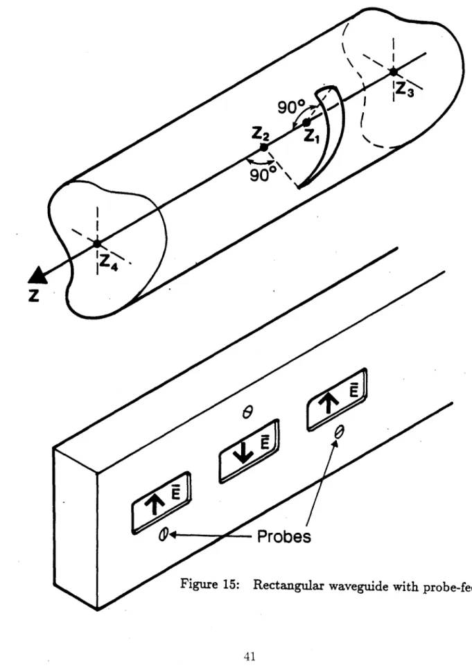
Consider a cylindrical waveguide of arbitrary cross-section as shown in Figure 14. The fields in such a guidecan be written in terms of TEmn and TMmn, modes, where TE (transverse electric)rmodes contain no E, and TM (transverse magnetic) modes contain no H,. The fields of these modes are
E = Etmn exp(~j:Fmnz) (52)
Ht,
=iHtmn
exp(Fjmnz)
(53)'
=
jHmn exp(Tj,3mnz)(54)
for the TEmn modes and
Cylindrical waveguide of arbitrary cross-section with arbitrary slot.
Probes
Figure 15: Rectangular waveguide with probe
-fed slots.
Figure 14:
90*
90*
IzN.
H'm,
±H'exp(Tjimnz)
(56)
Emn
jEOmnexp( Fj3miz)(57)
for the TMmn modes, where /mn is the guide propagation constant of the mode with mode numbers m and n, fields varying as exp(jwt - jk - r) are assumed, and
quantities with a 0-subscript have unit amplitude, are pure real, and depend only on m, n, x, and y. The waveguide modes are orthogonal over the cross-section of the waveguide, that is,
f(EOm x A~m lP HO,)ds =
{ 2Smn iftm=pand n = q
0
otherwise
(58)
where Smn is the Poynting energy flux of the mnth mode with unit amplitude32] Placing a self-excited slot from z, to z2 in the wall of the infinite waveguide
will excite waves in the guide that travel away from the slot. The wave fields are
E, =
AmnEmnexp(--jmnz)z > z
2(59)
mnE
= BmnEtjmnexp(jmnz) z < Z, (60) mnHt
= AmnHjmnexp(-jImnz) z > z2 (61) mnHt
= BmnH'mnexp(jOlmnz) z < Z1 (62) mnzwhere the coefficients Amn and Bmn are the amplitudes of the mnth mode traveling
an additional relation is needed. Assuming Eg, H9 and Et, Ht are two fields that
satisfy Maxwell's Equations in free space gives
V -
[E,
xHt] = V - [Et
xHg].
(63)
Using the divergence theorem yields
/;(EgxHt-EtxH,)-dA
= 0
(64)
where the integration is over a closed surface S.[ 1
We apply this equation to evaluate Amn, choosing a surface S that includes the plane sections at z3 and z4 and the walls of the guide between these sections
(see Figure 14). We call the fields excited in the slot Eg, H. as given by Equations
59-62, and let Et, Ht be a mode with unit amplitude and indices m and n
prop-agating to the left in the waveguide. Integrating over the plane at z3 and using
the orthogonality relation (Equation 64) gives zero because the fields g and
t
are waves traveling in the same direction. Integrating at z4 gives - 4AmmSmn. For anormal waveguide mode, the tangential component of E must be zero at the metal wall. Therefore the second term of the integrand vanishes for the integration over the wall and we obtain
4AmnSmn = -
(E,
xHt) - dA
(65)
-(iEHin + E;H, mn) exp(jI3mnZ)dA (66)
where the superscript -r indicates quantities in the direction 2 x i where fi is the normal to the guide surface. Following a similar procedure with Et, Ht a normal mode of indices mn traveling to the right yields
4B.nSmn = (-jE;H'n +
EH
,)
exp(-jimnz)dA. (67)These relations can be written in terms of the surface current Kmn that would exist in the region of the slot if there were no slot. The above equations then become
4AmnSmn =
j
(JE;Kn -- EgK ) exp(j3mnz)dA (68)4BmnSmn = (tEK n + EgKi) exp(--j3mnz)dA (69)
where Ki and K depend only on m, n, X, and y.
Proceeding to the explicit evaluation of the slot conductance; we are interested
in resonant slots (perimeter :: A) in rectangular waveguide that are long and narrow, with the long axes parallel to the guide axis (see Figure 15). The guide propagates only the dominant TE10-mode. For this case we would expect that Amn = Bmn
because the slot is symmetric in z. In the slot, Eg = 0 so the second terms in the integral vanish. Also, Kin is constant and Eg is an even function along the slot, so that only the real parts of the phase factors contribute to the integrals, resulting in Amn = Bmn. Thus the slot is a shunt element in the transmission-line model of
the waveguide. The following assumptions are made:[32 [33]
1. 2 loglo(length of slot/width of slot)


![Figure 10: Waveguide grill, as used by Pinsker, et. al. [20].](https://thumb-eu.123doks.com/thumbv2/123doknet/14530609.533508/38.918.92.854.33.1018/figure-waveguide-grill-as-used-by-pinsker-et.webp)