Publisher’s version / Version de l'éditeur:
Vous avez des questions? Nous pouvons vous aider. Pour communiquer directement avec un auteur, consultez la première page de la revue dans laquelle son article a été publié afin de trouver ses coordonnées. Si vous n’arrivez pas à les repérer, communiquez avec nous à [email protected].
Questions? Contact the NRC Publications Archive team at
[email protected]. If you wish to email the authors directly, please see the first page of the publication for their contact information.
https://publications-cnrc.canada.ca/fra/droits
L’accès à ce site Web et l’utilisation de son contenu sont assujettis aux conditions présentées dans le site
LISEZ CES CONDITIONS ATTENTIVEMENT AVANT D’UTILISER CE SITE WEB.
Fire Study (National Research Council of Canada. Division of Building Research), 1960-07-01
READ THESE TERMS AND CONDITIONS CAREFULLY BEFORE USING THIS WEBSITE.
https://nrc-publications.canada.ca/eng/copyright
NRC Publications Archive Record / Notice des Archives des publications du CNRC :
https://nrc-publications.canada.ca/eng/view/object/?id=574167b9-cead-43f3-b3dc-17104907daa2 https://publications-cnrc.canada.ca/fra/voir/objet/?id=574167b9-cead-43f3-b3dc-17104907daa2
NRC Publications Archive
Archives des publications du CNRC
For the publisher’s version, please access the DOI link below./ Pour consulter la version de l’éditeur, utilisez le lien DOI ci-dessous.
https://doi.org/10.4224/40001353
Access and use of this website and the material on it are subject to the Terms and Conditions set forth at
Fire test of a plank wall construction
ANALYZED
NATIONAL
RESEARCH
COUNCILCANADA
DIVISION OF BUILDING RESEARCH
FIRE
TEST O F APLANK
WALL CONSTRUCTION .by
T. Z. Harmathy
F i r e Study No. 2
of the
Divieion of Building Research
OTTAWA
FIRE TEST OF A PLANK WALL CONSTRUCTION by
T. 2.
HarmathyThis report describes a f i r e test on a plank wall construction requested by the Associate Committee on the National Building Code and carried out September 22, 1959.
Description of Specimen
The test specimen was a representative sample of a wall construction widely used in the province of Quebec. Constructional details and materials used a r e shown in Fig. 1, Additional data a r e a s follow: (iii) (iv)
(4
(vi) (vii)(i) White pine lumber was roughly sawn; it contained from
9.0 to
9.
2 per cent mois tur e on the day of the test.(ii) Gypsum wallboards complied, according to the manu- facturer's statement, with Specification A82.27- 1950 of the C ~ n a d i a n Standards Association.
Bricks were of red clay from local source; their moisture content was less than 2 per cent on the day of the test.
Mortar was of portland cement-lime
-
sand type and contained l e s s than 2 per cent moistyFe on the day of the test.Galvanized metal ties wexe made from 20-gauge steel strips of 1-in. width. Over -all length was 4$ in.
Building paper was asphalt-saturated felt paper, approxi- mately 15.0 lb per 100 s q ft.
Vapour b a r r i e r paper was duplex vapour seal paper, approximately 2.9 lb per 100 s q ft.
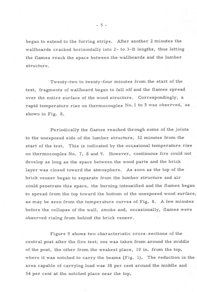
Figures 2 and 3 show the specimen during construction from the direction of the unexposed mrface. Figures 4 and 5 a r e pictures taken from both sides of it. The speeimen had aged for 32 days at the time of the &%,st.
Testing Procedure
The test was carried out in accordance with ASTM Specifi-
cation E- 119. The furnace temperature was measured by nine sym-
metrically disposed thermocouples enclosed in 13/16-in. 0. D. Inconel
tubes of 0.035-in. wall thickness; the tubes were equipped with wrought steel caps at the tips. Both the individual temperatures at nine points of the furnace and the average of the nine temperatures were recorded. The fuel input into the furnace was controlled in such a way that the average temperature could follow the prescribedbtemperature- time correlation.
An a r e a of the specimen 12 by 12 ft (that covered with the gypsum wallboards) was exposed to the flames, and the combustion chamber was sealed against the specimen along the asbestos felt s t r i p s and the concrete beam.
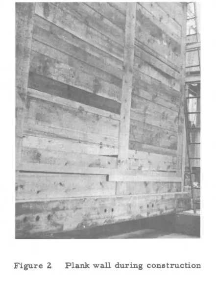
The unexposed surface temperature was measured by nine thermocouples covered with standard asbestos pads, 6 in. square and 0.4 in. thick, disposed as required by ASTM Specification E- 119. In addition, two thermocouples were cemented to the brick surface as
shown in Fig. 6. The location of the eleven thermocouples on the
unexposed surface can be seen in Fig. 4.
In order to examine the spread of the flames through the wall ten additional thermocouples were placed inside the wall specimen, five (No. 1 to 5) between the vapour b a r r i e r paper and the lumber
structure and five (No. 6 to 10) on the opposite side of the lumber underneath the building paper cover. These thermocouples were also
The lumber structure was subjected to a vertical load of
330 to 400 lb per ft. No load was imposed on the brick veneer layer at any time during the test.
A detailed description of the fire test facilities of the National Research Council i s available (1).
Results
Variation of the average furnace temperature i s plotted in Fig. 7. As the burning of the lumber structure developed, the fuel input into the furnace was decreased and finally cut off completely (at about 25 minutes from the s t a r t of the test), although the furnace temperature could not be prevented from rising considerably above that prescribed by the standard for a further period of about 20
minutes.
The temperature distribution inside the furnace was not particularly good a s there was sometimes a difference of a s much a s
400°F between the temperatures at the top and those at the bottom. However, since the heat was supplied by the combustion of the lumber, there could be little control over temperature distribution.
After 47 minutes deterioration of the wall became more and
more noticeable. The lumber structure began to buckle under the applied
load and thus to exert a thrust on the brick veneer layer. The brick layer gradually separated from the lumber structure at the top half of the wall, especially at the upper right hand corner. At 57 minutes the brick layer finally became unstable and overturned, pulling with it the remainder of the wood structure. The time of collapse i s marked in Fig. 7 with an arrow pointing upwards.
The a r e a under the curve of the average furnace temperature (above 68OF baee) for the 57-minute period ie 81, 210°F min, 4. 8 p e r cent l a r g e r than that under the etandard temperature-time curve for the same period (77,460
"F
m i n ) , but within the allowable*
10 p e r cent limits.P a r a g r a p h 5(c) of ASTM Specification E- 119 rules that the time of f i r e endurance should be corrected for the variation of furnace exposure f r o m that p r e s c r i b e d i f i t might affect the classification of the structure. Since the a r e a under the curve of the average furnace temperature for the f i r s t
$
x 57 = 43 minute period (the end of which i s marked with an a r r o w pointing downward in Fig. 7 ) i s 58,730 O F min,and that under the standard curve for the s a m e period i s 55,180 O F min,
the correction i s
where 3240 O F min i s a correction for the t h e r m a l lag of the furnace
thermocouples during the f i r s t p a r t of the test. The c o r r e c t e d f i r e endurance period i s therefore T
=
57(1 -f 0.0405)=
59. 3 min.The variation of temperature at different points inside the wall i s shown in Fig. 8. The temperature of the unexposed surface of the specimen did not show any noticeable r i s e above room tempera- ture throughout the test.
Discussion
If the curves of Fig. 8 a r e compared with the r e s u l t s of visual observation, an interesting picture of the spread of f i r e through the wall may be obtained.
In 10 minutes a l l paper cover burned off the exposed side of the gypsum wallboards ; 4 minutes l a t e r the joints opened and flames
began to extend to the furring strips. After another 2 minutes the wallboards cracked horizontally into 2- to 3-ft lengths, thus letting the flames reach the space between the wallboards and the lumber structure.
Twenty-two to twenty-four minutes from the s t a r t of the t e s t , fragments of wallboard began to fall off and the flames spread over the entire surface of the wood structure. Correspondingly, a
rapid temperature r i s e on thermocouples No. 1 to 5 was observed, a s
shown in Fig. 8.
Periodically the flames reached through some of the joints to the unexposed side of the lumber structure, 32 minutes from the s t a r t of the test. This i s indicated by the ocqasional temperature r i s e
on thermocouples No. 7, 8 and 9. However, continuous f i r e could not
develop a s long a s the space between the wood p a r t s and the brick layer was closed toward the atmosphere. A.s soon a s the top of the brick veneer began to separate from the lumber structure and a i r
could penetrate this space, the burning intensified and the flames began to spread from the top toward the bottom of the unexposed wood surface, a s may be seen from the temperature curves of Fig. 8. A few minutes before the collapse of the wall, smoke and, occasionally, flames were observed rising from behind the brick veneer.
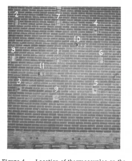
Figure 9 shows two characteristic cross-sections of the central post after the f i r e test; one was taken from around the middle of the post, the other from the weakest place, 10 in. from the top,
where i t was notched to c a r r y the beams (Fig. 1). The reduction i n the
a r e a capable of carrying load was 38 per cent around the middle and 54 p e r cent at the notched place near the top.
Reference
( 1 ) Shorter,
G,
W e ,
and T. 2. Harmathy. Fire Endurance TestFacilities at National Research Council. N. R. C.
,
D. B. R.,
W
.
Nz
a o V)--
IL a I- 0 W (U a w "2
* W -' g 8 ~ ;.. I- O-e
W * 0 J - l8
2
=
2 a =- -14%' a u - 3 a 3s
s'
g
;.. g =* m w o V) m I- 0 'UFigure 4 Location of thermocouples on the
Figure 5 Furnace-side surface of the finished specimen
W
=
WALL
T H =
1
HERMOCOUPLE
WIRES
C =
CEMENT
;
FIGURE
6
NON -STANDARD METHOD OF MEASURING
THE
TEMPERATURE OF THE UNEXPOSED SURFACE
AVERAGE FURNACE TEMPERATURE
-
-
STANDARD TEMPERATURE-TIME CURVEI t
I
30 TIME, MINUTESF I G U R E
7
V A R I A T I O N
OF FURNACE T E M P E R A T U R E
Figure 9 Two sections of the central post after the fire test