Prof. W. A. Rosenblith A. E. Albert F. Gordon
Dr. J. S. Barlow* R. M. Brown R. L. Koehler
Dr. M. A. B. Brazier* J. L. Freeman W. B. Lehmann Dr. L. S. Frishkopf C. D. Geisler E. Marcus Dr. N. Y. S. Kiang R. A. Goetz M. H. Reiss Dr. T. T. Sandel M. H. Goldstein, Jr. D. S. Shefrin A. AMPLITUDE AND LATENCY MEASURING INSTRUMENT WITH
DIGITAL OUTPUT (ALMIDO) (1)
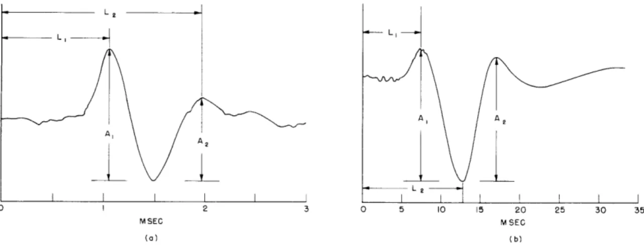
When a brief auditory stimulus is presented to the ear of an anesthetized cat, an electrode placed near the round window of the cochlea will detect a response of the sort represented in Fig. XV-la. A second electrode, placed on the auditory cortex, records a response whose time course is indicated in Fig. XV-lb. There has been a considerable amount of interest in both the amplitude and latency of the peaks that occur in these responses (2, 3, 4). The method heretofore employed in these measurements - photo-graphing from an oscilloscope and measuring on a microfilm reader - is time-consuming and effectively limits the collection of data. In an attempt to achieve more rapid analysis, an amplitude quantizer (5) and a latency measuring instrument (6) were constructed in
1954. The usefulness of these early models was seriously impaired by limited resolving power on the one hand, and inconvenient operation and display on the other. Consequently, a new instrument, measuring both latency and amplitude, was developed.
1. Specifications
In ALMIDO, a manually adjusted time gate selects the portion of the response that is to be measured. The peak-to-peak amplitude and the latency of one peak of a response (either peripheral or cortical) can be measured simultaneously. The amplitude is quan-tized into 1 of 100 levels with an accuracy of ±1. 5 levels. The peripheral latency is quantized into 10-isec levels with an accuracy of ±15 sec; the cortical latency is quan-tized into 100-isec levels with an accuracy of ±150 1sec. ALMIDO can accommodate an
amplitude change of five-to-one and still maintain the latency accuracy.
The measurements are read as binary coded decimals in electrical form. This out-put can then be used to activate a set of neon indicators, an electric typewriter, a histogram recorder, or any combination of these. The typewriter can print sequential data at a maximum rate of one measurement per second. The histogram recorder accu-mulates on Veeder-Root counters the number of times an amplitude occurs in each of 20 consecutive levels; the maximum recording rate is 15 measurements per second. If the stimulus rate is faster than the printing rate, the responses will be sampled at the highest printing (or recording) rate. ALMIDO requires only 3 msec after the response to com-plete both amplitude and latency measurements; therefore, a read-out rate of 300/sec could be maintained (e. g., by photographing the neon lights), if necessary.
From the Neurophysiological Laboratory of the Neurology Service of the Massachusetts General Hospital.
Fig. XV- 1.
AL 2 I I I I I I I I 2 3 0 5 10 15 20 25 30 35 M SEC M SEC (a) (b)(a) Typical peripheral response to a brief click (at t = 0) from an anesthetized cat. N1 and N2 are the first and second neural
components (see ref. 3). L1 and L2 , A1 and AZ, indicate the
latencies and amplitudes of the first and second neural peaks.
By electrophysiological convention, negative potentials read up.
(b) Typical cortical response to a brief click (at t
=
0).
Al1 and
Ag, L
1and L
2indicate the amplitude and latency of the peaks
of interest (4).
Negative, read up.
PERIPHERAL AMPLITUDE ERROR
THEORETICAL MINIMUM FOR ± ILEVEL ACTUAL ERROR BASED ON 164 MEASUREMENTS I 2 MAGNITUDE OF AMPLITUDE ERROR IN LEVELS o 1-Uj z o gaju U.-I r'C SI0 n I-LL°c 00,
I
0 of (LZ < U trt Ir Uj wt L' 0(Du 0 r M < U Q:Q PERIPHERAL LATENCY ERRORa' 1.0
< THEORETICAL MINIMUM 0
O.8e FOR ± I LEVEL
o 06 '04 ACTUAL ERROR 0 BASED ON 164 O2 MEASUREMENTS 0 I 2 MAGNITUDE OF LATENCY ERROR IN UNITS OF 10 SEC
CORTICAL AMPLITUDE ERROR
10 THEORETICAL MINIMUM 0.8 FOR + ILEVEL 0.6 04 ACTUAL ERROR B- ASED ON 169 02 MEASUREMENTS O I 2 MAGNITUDE OF AMPLITUDE ERROR IN LEVELS
CORTICAL LATENCY ERROR
1.0O
THEORETICAL MINIMUM 0-8 FOR t 0.1 LEVEL,
READING ONLY TAKEN
0.6i- OF INTEGRAL LEVELS
0.4- ACTUAL ERROR
BASED ON 159
02 _ MEASUREMENTS
O I 2
MAGNITUDE OF LATENCY
ERROR IN UNITS OF IOOPSEC
Fig. XV-2. Measurement error of ALMIDO. Oscilloscope traces are taken as reference.
0 I--ot 1.01 EiQ 08 z Z 0.8-Uj WI-a060 04 S-0.4 000 Ca -o O
2.
Performance
Oscilloscopic traces of electric responses were photographed and measured
simul-taneously by ALMIDO.
The film was read on a microfilm reader with the scales adjusted
to correspond approximately to the measurements of the instrument.
The difference in
the scales appeared as a difference between the means of the two sets of measurements,
and was subtracted from one set.
The resultant error curves show the difference between the read oscilloscope traces
and the measurements by ALMIDO (Fig. XV-2).
These error curves are compared with
the minimum error inherent in the digital measurement that was used (±1 level for all
but the cortical latency; the latter is measured to ±0. 1 level, but only integral levels
are read).
3.
Operation (Fig. XV-3)
The response signal must be prepared for measurement by amplification and
time-gating.
The signal is amplified from the 1-volt level to a 50-volt level by two cascaded
dc amplifiers that are gain-stabilized.
An inverter permits the use of either the positive
or negative peak of the response for the latency measurement.
A clamp gate follows the amplifiers and allows time selection (t
=
0 at the click
sig-nal) of the portion of the response that is to be measured.
The gate delay and gate
duration are each controlled by a monostable multivibrator.
Spikes from the
differen-tiated leading and trailing edges of the gate signal are mixed with the response for
oscilloscope presentation of the gate position.
Prior to the unclamping of the clamp circuit, most of the response signal is
devel-oped across a condenser connected between the amplifier and the clamp circuit. This
establishes the base line of the response at ground level when the time-selected period
begins.
A similar clamp circuit is used between the two cascaded amplifiers to prevent
clipping of the signal by the second amplifier if there is a large background signal.
4.
Measurement of Latency
After the response signal is amplified and time-selected, each successively larger
positive peak (of the selected part of the response) is detected for latency measurement.
A condenser is charged through a diode to each successively larger positive peak.
A
level detector, connected across the charging diode, indicates that a peak has been
reached each time the signal across the diode goes negative.
A counter keeps time from the click signal by counting pulses from a 100-kc time
base.
The count is stored in a storage register each time a successively larger
posi-tive peak is detected.
The counter is given time to settle from the last count before the
storage cycle is completed.
AMPLITUDE AND
GATED RESPONSE
Ai m PL;FIER -Fl.. A.2N04 I1 I'll o4 I .. CATHODE
A = TO CL G 10 FOLLOWER
CLAMP CLAMP
NATE
CONTINUOUS SINE WAVE TROL
SED FOR THE INPUT P S
GATGNE MG UP
AMPLIFIER RESPONSE SIGNAL OUTPUT
WITH GATE MARKERS
START GATE DELAR GATE DURATION
EGATED STIMULUS
STIMALA S AETELTOR fl
TRIGGER (STARTS MEASUREMENT CYCLE)
SIGNAL
GATE CONTROL BY
DISPLAY TIMER ANP
DIGITAL RECORDERS
-FLEVEL
--- 2ETECTOR
NEGATIVE PEAK NEGAT VE PEAK STORAGE COINCIDENCE SIGNAL
SA MPLITUDE
SPOSITIVE PEAK
COINCIDENCE SIGNAL
POSITIVE PEAK -[ AMp RATDE STORAGE
GATE SIGNAL
-F
RAMP
START GENERATOR
Fig. XV-3. Block diagram of ALMIDO.
RESPONSE SIGNAL INPUT NOTE: A J ,,/\J-./ DIGITAL OUTPUT IOO-KC ORYSTAI OSCILLATOR
4 IUD
5. Measurement of Amplitude
The positive and negative peak amplitudes of the time-selected portion of the response are charged into condensers through diodes. After the response signal is gated off, the stored peaks are compared with a voltage ramp, which produces a time interval proportional to the peak-to-peak amplitude. The interval is timed by gating the time base into the counter for the duration of the interval (the counter is no longer needed as a clock for the latency measurement).
6. Sampling Fast Stimulus Rates
The stimulus trigger signal, detected by a level detector, removes the previous measurement and starts a new measurement cycle. A gate prevents the detected trigger signal from starting a new measurement until the old measurement has been recorded or displayed for a preset time. Thus stimulus rates that are faster than the recording rate can be sampled.
R. L. Koehler
References
1. R. L. Koehler, S. M. Thesis, Department of Electrical Engineering, M. I. T., 1956. 2. J. Macy, Jr., Quarterly Progress Report, Research Laboratory of Electronics,
M.I.T., July 15, 1954, pp. 75-80.
3. L. S. Frishkopf and W. A. Rosenblith, Quarterly Progress Report, Research Laboratory of Electronics, M. I. T., Oct. 15, 1954, pp. 87-94.
4. D. H. Raab and R. M. Brown, Quarterly Progress Report, Research Laboratory of Electronics, M. I. T., April 15, 1954, pp. 75-76.
5. K. Putter, Quarterly Progress Report, Research Laboratory of Electronics, M.I.T., July 15, 1953, p. 88; Oct. 15, 1953, pp. 50-51; Jan. 15, 1954, pp. 72-73. 6. A. K. Hooks, Quarterly Progress Report, Research Laboratory of Electronics,
M.I.T., April 15, 1954, pp. 79-80.
B. EQUAL LOUDNESS JUDGMENTS FOR MONOTIC AND DIOTIC CLICKS
According to Fletcher and Munson (1), a sound should be perceived twice as loud when it is heard with both ears as it is when heard with one. Their results showed that for a monotic loudness level of 72 db, a diotic level of 60 db sounded equally loud, a difference of 12 db. A monotic level of 25 db sounded equally loud as a diotic level of 20 db, a difference of 5 db. By extrapolation, a difference of 3 db would be expected at threshold, a value that might be anticipated on the basis of equating power and loud-ness. Causse and Chavasse (2) showed essentially the same phenomena, although their greatest difference was only 6 db at a sensation level of 35 db. Both studies used tonal
(XV. COMMUNICATIONS BIOPHYSICS)
RIGHT EARI I I I I I
stimuli
and showedstability
over a fairly broadLEFT EAR I f I I frequency range.
f IME The type of binaural summation discussed
above seems well established for pure tones; how-Fig. XV-4. Input schedule (f =
frequency of click). ever, little is known about the loudness function when the stimuli are monotic clicks compared with diotic clicks. Consequently, we asked sub-jects to adjust the intensity of clicks presented simultaneously to both ears until they
sounded as loud as a monotic standard, at the following repetition rates: 2, 4, 6. 5, 8, 10, and 12 clicks per second.
Subjects were presented with an alternation of single clicks, first to one ear, then to both, as shown in the input schedule in Fig. XV-4. Because of this sequence of single
clicks, the judgment was increasingly difficult as the repetition rate of the clicks increased, which accounts for the terminal value of 12 clicks per second. Judgments were made by the method of adjustment, with the monotic clicks as standards.
Figure XV-5 presents the results of the experiment. The curves represent the aver-age of 10 judgments from each of 5 subjects for each point on the curves. It is readily seen that repetition rate is not a critical variable, the differences between the various rates being insignificant. However, the equal loudness judgments vary markedly with the intensity level of the monotic standard. It is evident that clicks are not exhibiting the loudness growth pattern expected from the tonal studies of Fletcher and Munson and of Causs6 and Chavasse. In their studies, there was an increasing disparity as level increased. In our study, there is a decreasing disparity as level increases, until at
zo7-t- o > 5~ + -++ 8 z 34 -44 -54 -64 0 -74 - CLICK RATE 00 0 1 0O 6.5 + 8 j o 10 a 12 MEAN OF ALL -34 -44 -54 -64 -74 -84 RATES
MONOTIC INTENSITY LEVEL (DB RE I VOLT AT PHONE)
high intensities, for a given level, the monotic click is actually perceived louder than the diotic clicks.
We conclude, tentatively, that the data shown here cannot support generalization of the concept of binaural summation to include impulsive signals such as clicks. It should be noted, however, that a relationship might exist between the loudness of these stimuli and their localization. The diotic clicks are heard as centered in the head, while the monotic click is heard as laterally displaced to the ear that is stimulated. Further investigation is indicated.
T. Sandel, F. Gordon
References
1. H. Fletcher and W. A. Munson, J. Acoust. Soc. Am. 5, 82-108 (1933).
2. R. Causs6 and P. Chavasse, Compt. rend. Soc. Biol., Paris 86, 405 (1942); I. J. Hirsh, Psychol. Bull. 45, 193-206 (1948).
C. EQUAL LOUDNESS JUDGMENTS FOR CLICKS AND BROADBAND NOISE
Clicks, because of their "punctiform" character in time, their spectral character-istics, and their clearly visible evoked responses, are particularly useful stimuli in neurophysiological studies of the auditory nervous system. The characteristics of neuro-electrical responses to these stimuli have been widely investigated and functional
relationships have been established. However, because of instrumental difficulties, and the general difficulty of achieving adequate measures of loudness, very little is known about the loudness of clicks. It should be noted, however, that although signals characterized electrically by instantaneous rise and decay have not been investigated, Steudel (1) measured loudness of signals of instantaneous rise and exponential decay.
We conducted preliminary studies for the purpose of relating the loudness of clicks to the loudness of noise, a stimulus of known loudness parameters. The signals used were 100-Fisec square electric impulses of negative polarity. Their transduced form was a fast, but not instantaneous, rising and falling unipolar peak of approximately 200-lsec duration.
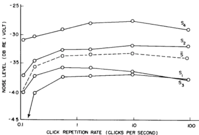
Five subjects, using the method of adjustment, made equal loudness judgments for different click repetition rates and for different intensity levels of standard, using both click and noise as standards.
Figure XV-6 shows the contours for the various repetition rates by subject. Clicks, at rates of 2, 10, 30, 50, 80, and 120 per second, were presented randomly and matched by the subjects. It is noted that, although there is large intersubject variation for any given repetition rate, the general configurations of the curves were the same. The
(XV. COMMUNICATIONS BIOPHYSICS) -25 > -30 Cr 0---0-__. _ ---- ---- o _ -35 -40 0.1 10 100
CLICK REPETITION RATE (CLICKS PER SECOND)
Fig. XV-6. Equal loudness contours for clicks and wideband noise with varying click repetition rate.
intrasubject variation showed a maximum of or = 3. 05 db.
It might be expected that, because the power in a train of clicks is proportional to the repetition rate, the loudness of the matching noise might exhibit a monotonic growth as the repetition rate increases. Obviously this is not true. The power in the click train approaches this loudness function only beyond 110 clicks per second.
Another possible explanation presents itself in Steudel's work. Using the previously mentioned fast rise-exponential decay signal, he varied the time constant of decay and obtained a curve that strongly resembles ours. Figure XV-7 compares our data with Steudel's. The ordinates are adjusted to show the disparity between the standard click level and the level of the variable noise judged equally loud. The abscissa presents the click data as the total time per second that stimulation is present; that is, at 100 clicks per second, with a click duration of 100 Lsec, the total stimulus time per second is
10 msec.
The equivalence of our data and Steudel's would suggest that in the case of the loud-ness of clicks, within the range investigated here rather than a simple power summation,
we are observing a growth of loudness that is proportional to the total time of stimula-tion per unit time, and that this process apparently terminates at approximately 3. 0 msec. Beyond this time value, increasing repetition rate no longer manifests a loudness growth.
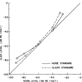
Again using the method of adjustment, we investigated the effect of standard level. All judgments were made with a repetition rate of 30 clicks per second. Standard levels used were -14, -34, -54, -74, -84 db re 1 volt at the phone. Both noise and clicks
were used as standards.
The results of this experiment are presented in Fig. XV-8. Values on ordinate and abscissa are attenuations re 1 volt at the phone. Notice that, when attenuation values
STIMULUS TIME (IN MSEC)
Fig. XV-7.
Comparison of equal loudness judgments,
using Steudel's time-constant decay values
and our click sound-time fraction values.
0 > -40 -J-6 _ -60 W 1-80 0 NOISE STANDARD CLICKS STANDARD -100 -80 -60 -40 NOISE LEVEL (DB RE I VOLT)
Fig. XV-8.
Equal loudness contour for clicks and wideband noise
(XV. COMMUNICATIONS BIOPHYSICS)
are plotted against one another, the middle range of intensity values shows nearly one-for-one correspondence between clicks and noise, although at both high and low values of standard, the noise must be reduced more in intensity to make the match. This result was not anticipated and we can offer no theoretically satisfactory interpretation for the slope of this curve.
T. Sandel, R. Goetz, E. Marcus
References
1. J. Steudel, H. F. T. (Leipzig and Berlin) 41, 116-128 (1933); S. S. Stevens and
H. Davis, Hearing (John Wiley and Sons, Inc., New York, 1938), pp. 155-159.
D. EFFECT OF VARYING NOISE LEVEL ON A READER'S VOICE LEVEL
Although it is well-known that people tend to raise their voices as the ambient noise level is increased, few attempts have been made to measure this effect quantitatively. By way of an introductory investigation, the effect of raising and lowering noise levels upon voice level was studied.
The output of a noise generator, properly filtered and amplified, was presented through earphones. Four subjects were instructed to read a passage aloud to an imagi-nary person located in the same acoustic environment; the subject's voice level was continuously recorded. The noise level was first raised from 35 db SPL to 95 db; whence it was lowered to 35 db SPL. The whole cycle was then repeated, the subject being exposed in all cases to each particular noise level for 20 seconds. This test was repeated four different times for each subject. The effects of filtering the noise (1), and of using ramp and impulse increments as well as step increments (2), were investigated in turn.
The variation in average voice level with noise level variation is quite similar, in all cases, to the nonlinear, double-valued curve shown in Fig. XV-9. The voice level for each speaker is normalized to his own voice level in the absence of noise, this initial voice level being identified as zero. The averages of these normalized voice levels are plotted as the experimental points. (The voice level for the second cycle of noise varia-tion does not differ appreciably from that of the first.) When the noise level was raised in step fashion, it took about 1. 5 sec for the voice level to change; there is no over-shoot. For the 20 sec during which the noise level stays constant, no decay of voice level is noticed. The difference in voice level for rising and falling noise level may be explained by an adaptation process which has a slower time-rate-of-change for decreasing noise levels than for increasing. The fact that the voice level is different before and after testing suggests that there is a relative reference level for the voice,
J 20-INCREASING >10- NOISE LEVEL N DECREASING J I NOISE LEVEL 0 o -I 35 45 55 65 75 85 95 NOISE LEVEL (DB SPL)
Fig. XV-9.
Normalized average voice
level versus noise level.
not an absolute one.
When the noise was filtered in several bands, the greatest increase of voice level for equal rms noise voltages (26 db) was observed for the 1000-cps lowpass band. This finding is not entirely unexpected, since voice power is concentrated in this band; hence, this low-frequency noise acts as an effective masker. Highpass filtering of the noise caused a much smaller increase in voice level. It was found that, when the noise level was raised in ramp fashion, the gap between "rising" and "falling" branches of the curve widened. Impulses of noise produced no noticeable change in voice level.
The adaptation mechanism should provide an interesting subject for further investi-gation. A more exhaustive study of transient behavior might lead to a model of the feedback mechanism by means of which voice level is controlled.
C. Geisler, D. Shefrin, M. Reiss
References
M. Reiss, S. B. Thesis, Department of Electrical Engineering, M. I. T., D. Shefrin, S. B. Thesis, Department of Electrical Engineering, M. I. T.
1956.
June 1956.
June
E. AVERAGE REACTION TIMES TO PURE TONES AS A FUNCTION OF AVERAGE INFORMATION
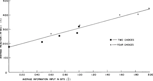
The reaction time to an auditory stimulus (pure tone) was investigated as a function of the average amount of information conveyed by that stimulus. The amount of informa-tion was varied by changing: (a) the number of alternative stimuli, and (b) the relative frequency of occurrence of any one stimulus, once the number of alternatives was fixed.
The experiment was divided into three parts: First, simple reaction times were measured for all the stimuli that would be used in the subsequent stages of the experi-ment; second, the number of different stimuli was fixed as two, and the average infor-mation per stimulus was varied from zero to one bit; third, the number of different stimuli was fixed as four, and the average information per stimulus was varied from zero to two bits.
(XV. COMMUNICATIONS BIOPHYSICS) 500 400 I.-( 300 0
•O - TWO CHOICES 200
2 Ox - FOUR CHOICES
100-0.20 0.40 0.60 0.80 1.00 1.20 1.40 1.60 1.80 2.00
AVERAGE INFORMATION INPUT IN BITS (I)


