Publisher’s version / Version de l'éditeur:
Vous avez des questions? Nous pouvons vous aider. Pour communiquer directement avec un auteur, consultez la première page de la revue dans laquelle son article a été publié afin de trouver ses coordonnées. Si vous n’arrivez pas à les repérer, communiquez avec nous à [email protected].
Questions? Contact the NRC Publications Archive team at
[email protected]. If you wish to email the authors directly, please see the first page of the publication for their contact information.
https://publications-cnrc.canada.ca/fra/droits
L’accès à ce site Web et l’utilisation de son contenu sont assujettis aux conditions présentées dans le site
LISEZ CES CONDITIONS ATTENTIVEMENT AVANT D’UTILISER CE SITE WEB.
Journal of the Engineering Mechanics Division, American Society of Civil
Engineers, 97, EM5, pp. 1431-1450, 1971-10
READ THESE TERMS AND CONDITIONS CAREFULLY BEFORE USING THIS WEBSITE.
https://nrc-publications.canada.ca/eng/copyright
NRC Publications Archive Record / Notice des Archives des publications du CNRC :
https://nrc-publications.canada.ca/eng/view/object/?id=58343593-818e-40da-8c50-2cd67c22ad60
https://publications-cnrc.canada.ca/fra/voir/objet/?id=58343593-818e-40da-8c50-2cd67c22ad60
NRC Publications Archive
Archives des publications du CNRC
This publication could be one of several versions: author’s original, accepted manuscript or the publisher’s version. / La version de cette publication peut être l’une des suivantes : la version prépublication de l’auteur, la version acceptée du manuscrit ou la version de l’éditeur.
Access and use of this website and the material on it are subject to the Terms and Conditions set forth at
Structure-ground interaction in earthquakes
S e r
no.
490
JATIONAL RESEARCH COUNCIL O F CANADA
c .
2
lSEIL NATIONAL D E RECHERCHES D U CANADA
BLDG
STRUCTURE-GROUND INTERACTION IN EARTHQUAKES
by
J. H. Rainer
Reprinted from
American Society of Civil Engineers
Journal of the Engineering Mechanics Division
Vol. 97, No. EM5, October 1971
pp. 1431
Research Paper No. 490
of the
Division of Building
OTTAWA
I
NO\1261971
1
DES SEISMES
5
J
' SOMMAIRE
1Un rnodile dquivalent de simple degrd de libertd (S.D.F.) est utilisd afin de
ddterrniner les ddplacernents relatifs des idifices
d
un dtage sous l'action de
sdisrnes en terrain dlastique. La rnithode prdsentde dvite les ddsavantages
d'employer individuellernent les perturbations au hasard ou celles
d
l'dtat
soutenu. Enfin, on prdsente aussi une dtude ddtaillde de paramitres.
October, 1971 e ; " " , , EM 5
fA.3
$..L
1i . ~ 3
Journal of the
ENGINEERING MECHANICS DIVISION
Proceedings of the American Society of Civil Engineers
STRUCTURE-GROUND INTERACTION IN EARTHQUAKES By Johann H. Rainer,' A. M. ASCE
INTRODUCTION
Analysis of the earthquake response of s t r u c t u r e s founded on a flexible foundation h a s recently received considerable attention. Although the ideal- ized s t r u c t u r a l models in such studies varied substantially in detail, they can generally be grouped into two main categories: (1) Those that employ com- p a r i s o n s of response due to a r b i t r a r y b a s e disturbances such a s recorded earthquakes (3,7) o r artificially generated earthquakes (10,11,12) and (2) those that used steady-state ground disturbances (5,9).
The response comparison between the interaction s t r u c t u r e and the fixed- b a s e s t r u c t u r e s u f f e r s f r o m the fact that the r e s u l t s may be m o r e sensitive to the a r b i t r a r y c h a r a c t e r i s t i c s of the disturbance than to the foundation ef- fects being studied. As the natural frequencies of the s t r u c t u r e change with the introduction of foundation flexibility, such a response comparison may show either a n i n c r e a s e o r a d e c r e a s e in response, simply because of the c h a r a c t e r i s t i c s of the p a r t i c u l a r exciting force used (3,7,11). Whether a r e - duction o r a n i n c r e a s e in r e s p o n s e i s obtained depends on the location of the s p e c t r a l peaks of the disturbance in relation to the natural frequencies of the fixed-base and interaction s y s t e m s . Certain g e n e r a l a s p e c t s of the interaction phenomenon can, therefore, b e masked by the c h a r a c t e r i s t i c s of the particu- l a r ground disturbance chosen. This complicating effect introduced by the frequency s h i f t w a s overcome by P e r e l m a n , e t al. (12) by comparing the seis- mic interaction response with the response of a single degree-of-freedom (SDF) s y s t e m having the s a m e natural frequency and subjected to the s a m e disturbance.
On the o t h e r hand, interaction studies that employ steady-state distur- Note.-Discussion open until March 1, 1972. To extend the closing date one month, a written request must be filed with the Executive Director, ASCE. This paper i s part of the copyrighted Journal of the Engineering Mechanics Mvision, Proceedings of the American Societyof Civil Engineers, Vol. 97, No. EM5, October, 1971. Manuscript was submitted for review for possible publication on January 26, 1971.
'Building Physics Section, Div. of Building Research, National Research Council of Canada, Ottawa, Canada.
bances a r e limited by the fact that the r e s u l t s cannot readily be applied to earthquake-type disturbances.
The method of analysis now presented helps to overcome the shortcomings of studies where steady-state o r random-typedisturbances a r e used by them- selves; in fact, it bridges the gap between the two techniques. To achieve this goal, a n equivalent SDF model i s derived, representing relative displacement f o r single-story interaction s t r u c t u r e s , that implicitly incorporates the ef- f e c t s of the flexible foundation p a r a m e t e r s . With this equivalent SDF the p r o p e r t i e s of the s t r u c t u r e a r e separated f r o m the influences of specific random-type disturbances. Thus the significant p a r a m e t e r s of the interaction p r o c e s s c a n b e readily identified and evaluated. When the interaction response to a given ground disturbance i s d e s i r e d , however, well established proce- d u r e s f o r SDF systems, s u c h a s numerical integration and response spectrum techniques, can be employed.
EQUIVALENT SDF MODEL FOR RELATIVE DISPLACEMENT F o r p u r p o s e s of dynamic analysis many single-story a s well a s m o r e complex s t r u c t u r e s can be idealized by a SDF system, i.e., a m a s s supported by a deformational spring, in turn mounted on a rigid base. If the base i s p e r - mitted to move horizontally a s well a s rotationally relative to the undisturbed ground, however, a ground-structure interaction system i s obtained. Such a system i s shown in Fig. 1, where the ground deforms under the dynamic loads that a r e applied by the b a s e to the half-space.
With the introduction of rocking and relative horizontal motion of the base, the original SDF system becomes a t h r e e degree-of-freedom system. T h r e e modal shapes can, therefore, be expected. F o r single-story s t r u c t u r e s the lowest mode will remain dominant, and under most earthquake disturbances the contribution of the secondand third modes to the total response of single- s t o r y s t r u c t u r e s c a n b e a s s u m e d negligible. T h i s study considers only the ef- fect of the lowest mode of the single-story interaction system.
With this simplification i t becomes possible to transform the interaction system into a n equivalent SDF model whose properties reflect the effects of the foundation interaction. Established techniques for SDF s y s t e m s may then be utilized. Briefly, the procedure i s to determine the SDF system that matches the interaction s y s t e m with r e s p e c t to i t s frequency response.
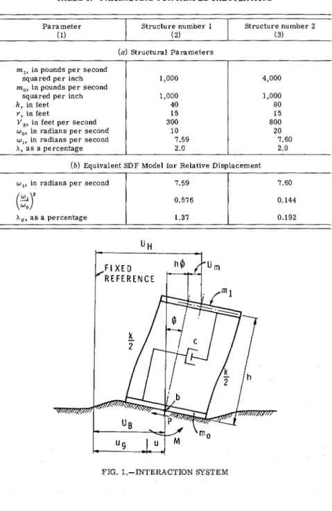
The technique i s developed in t e r m s of relative displacement, although i t i s s i m i l a r l y applicable to other structural p a r a m e t e r s such a s overturning moment. The p r o c e s s will be illustrated by two specific interaction s t r u c - tures, described in Table 1.
P r o p e r t i e s of Frequency Response Curves.-The dynamic c h a r a c t e r i s t i c s of a linear s y s t e m a r e completely determined by the frequency response curves. F o r a particular response p a r a m e t e r , e.g., relative displacement, the frequency response curve i s defined a s the ratio of response to d i s t u r - bance under steady-state conditions a s a function of frequency.
Frequency response c u r v e s a r e usually p r e s e n t e d i n t e r m s of a nondimen- sional response p a r a m e t e r such a s the ratio of the relative displacement a m - plitude to the ground displacement amplitude plotted v e r s u s frequency. In deriving a n equivalent SDF system, however, i t i s advantageous to plot the ratio of relative displacement amplitude to ground acceleration amplitude.
STRUCTURE-GROUND INTERACTION
TABLE 1.-PARAMETERS FOR SAMPLE CALCULATIONS
P a r a m e t e r
( b ) Equivalent SDF Model for Relative Displacement (a) Structural P a r a m e t e r s
w , , in radians p e r second 7.59
I
7.60Structure number 1 Structure number 2
4,000 1,000 80 15 800 20 7.60 2.0 m,, in pounds p e r second squared p e r inch m,, in pounds p e r second squared p e r inch h , in feet r, in feet V,, in feet p e r second w,, in radians p e r second w , , in radians p e r second A , a s a percentage
FIG. 1.-INTERACTION SYSTEM 1,000 1,000 40 15 300 10 7.59 2.0 A , , a s a percentage 1.37 0.192
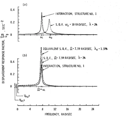
This r a t i o is t e r m e d the displacement response factor. Sample curves of the displacement response factor v e r s u s frequency a r e presented in Fig. 2(a) f o r the particular s t r u c t u r e (No. 1, Table l a ) . Although both a r e a l and an imagi- nary component a r e generally present, i t is satisfactory with s m a l l amounts of damping to consider m e r e l y the vectorial sum of the r e a l and imaginary components, i.e., the amplitude frequency response curve. The l a t t e r will be used exclusively herein.
Derivation of Equivalent
SDF
Model.-For the particular s t r u c t u r e (No. 1, Table la) Fig. 2(a) p r e s e n t s the displacement response factor f o r the fixed- b a s e s t r u c t u r e with resonance frequency w, and the s a m e p a r a m e t e r for theINTERACTION, STRUCTURE NO. 1
IL
S. D. F. U,-
10 RADISEC,A
-
2% '4 WoI I I I I I I I I I t I t I
0 4 8 12 16 20 24 FREQUENCY, RADISEC
FIG. 2.-FREQUENCY RESPONSE CURVES FOR STRUCTURE NO. 1, RELATIVE DISPLACEMENT
interaction system with fundamental resonance frequency w,. Two significant f e a t u r e s in these c u r v e s a r e apparent: (1) A d e c r e a s e of resonance frequency has o c c u r r e d a n d (2) the i n t e r c e p t a t z e r o frequency i s the s a m e for the fixed- b a s e s t r u c t u r e a s for the corresponding interaction system.
Fig. 2(b) shows the frequency response c u r v e s for: (1) The interaction s t r u c t u r e in the solid line with fundamental resonance frequency w,; (2) the SDF system with resonance frequency
D
= w, and damping ratio h = 2%; a n d (3) the equivalent SDF model for relative displacement of the interaction structure. With r e f e r e n c e to Fig. 2(b), the transformation of the interaction p a r a m e t e r into the equivalent SDF i s achieved in t h r e e main stages: (1) De- termination of p r o p e r resonancefrequency; (2) determination of a multiplica-EM 5 STRUCTURE-GROUND INTERACTION 1435 tion factor for the entire frequency response curve; and (3) determination of an equivalent damping coefficient to account for the magnitude of the frequen- cy response curve a t resonance.
Determination of Fundamental Resonance Frequency.-The fundamental resonance frequency for the interaction system may be computed by deter- mining the eigenvalues of the system once a standard eigenvalue problem h a s been formulated. This will be described further in the section Interaction Model. Alternatively, a numerical search of the response curves may be em- ployed to detect the peak amplitude located a t the resonance frequency, w,, of the fundamental mode. This latter method was used to obtain the numerical r e s u l t s presented herein.
Multiplication Factor for Frequency Response Curve.-The multiplication factor for transforming the interaction frequency response curve into that of an SDF system i s obtained by comparing the z e r o frequency intercepts of the respective curves shown in Fig. 2(b). The z e r o frequency intercept corre- sponds to the c a s e where the interaction structure i s subjected to a constant base acceleration Ug. F o r both a n interaction system and a fixed-base struc- ture this induces an inertia force in the top m a s s , m,, equal to m,iig, which in turn causes a relative interstory displacement Urn = mliig/k in which k =
interstory spring stiffness. F o r iig = 1
The SDF system with resonance frequency 51, however, has a z e r o frequency intercept of 1/n2. The frequency response curve for relative displacement of the interaction structure i s thus brought to coincide with that of the equiva- lent SDF model by multiplying the f o r m e r by ~ : / 5 1 ~ = w,2/wf. This results in the dashed curve shown in Fig. 2(b).
Equivalent Damping.-The third p a r a m e t e r required for a complete de- scription of the equivalent SDF model i s the equivalent damping ratio A,. This can be determined simply from the magnitude, Me, of the resonance peak f o r the nondimensional frequency response curve for urn/ug
in which Me = MI (w,/w,)~ and MI = peak amplitude of the nondimensional frequency response curve for relative displacement urn/ug a t resonance fre- quency w,.
Because all amplitudes of the frequency response curve have been in- creased by (w,/w,)~, the response computed with the aforementioned equiva- lent SDF i s too large by the factor (w,/w,)~.
With these three p a r a m e t e r s , i.e., fundamental resonance frequency w,, multiplication factor (w,/w,)~, and equivalent damping A,, the displacement response curve of the equivalent SDF model and that of the interaction sys- tem multiplied by ( W ~ W , ) ~ a g r e e closely over the complete frequency range, even when frequency-dependent foundation p a r a m e t e r s a r e considered.
INTERACTION MODEL
The interaction system under consideration i s shown in Fig. 1. This model is the s a m e a s that used by P a r m e l e e (9) and therefore only the main points
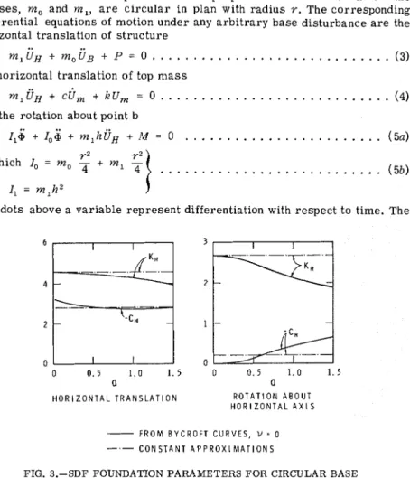
of the derivation will be presented. F o r purposes of this derivation both the masses, mo and m , , a r e circular in plan with radius r . The corresponding differential equations of motion under any arbitrary base disturbance a r e the horizontal translation of structure
the horizontal translation of top m a s s
and the rotation about point b
r2 in which lo = m o -
+
m l'1
4
. . .
( 5 b )I, = m l h 2
and dots above a variable represent differentiation with respect to time. The
a a
H O R I Z O N T A L T R A N S L A T I O N R O T A T I O N A B O U T H O R I Z O N T A L A X 1 S
-
F R O M B Y C R O F T C U R V E S , V = 0C O N S T A N T A P P R O X I M A T I O N S
FIG. 3.-SDF FOUNDATION PARAMETERS FOR CIRCULAR BASE
remaining symbols aredefinedin Fig. 1. Under the influence of a steady-state ground displacement ug = wezPt, the resulting complex amplifications X, Y, and Z of the displacement components U B , @I, and Urn a r e given by
The forces between the base and the half space a r e given by
. . .
EM
5
STRUCTURE-GROUND INTERACTION 1437 in which A and B = dynamic stiffness coefficients that relate the generalized f o r c e s and the corresponding displacements under sinusoidal excitation. F o r a c i r c u l a r base- L H
in which K H =
&
CH = I f 1 ~ ) 2 i a ( f 2 ~ ) ''
G = s h e a r modulus of ground; Y = radius; a = nondimensional frequency =
pr/V,;
p
= c i r c u l a r frequency, in radians p e r second; V , = shear wave ve- locity of ground; and i =m.
T e r m s K H and K R a r e horizontal and rota- tional stiffness factors and CH and C R , horizontal and rotational damping factors for the circular footing on the elastic half space, shown by the solid lines in Fig. 3. The values for f l and f 2 used herein a r e those obtained by Bycroft for a circular disc on an elastic half space ( 2 ) .Substitution of the preceding relations into Eqs. 3 to 5 and simplification gives:
and a = m,/ml;
0
= m , / ( p ~ ) ~ ; q = (h/rlZ; W: = k/m,; X = relative interstory damping ratio; and p = density of ground. Note that, in general, wh, w s , AH, and XR in Eq. 12 a r e frequency-dependent quantities; wH can be interpreted a s the horizontal resonance frequency of the base alone; and wR a s the rock- ing frequency of the m a s s m , with moment of inertia I, = m,hz. T e r m s X gand XR a r e the corresponding relative damping ratios f o r horizontal and rocking motions, respectively.
Solution f o r the steady-state amplification vector T i yields
g
in which the matrix inversion indicated may be c a r r i e d out numerically by computer.
T e r m T,d r e p r e s e n t s the displacement response vector of the interaction
g
system to a steady-state ground displacement u g a t any frequency and i s com- monly called the transfer function for the system (4). F r o m the definition of frequency response curve already given i t may be seen that for a continuous range of frequencies the frequency response c u r v e s representing displace- ment ratios may be evaluated from Eq. 14.
The t r a n s f e r function a s well a s the frequency response curves f o r other time derivatives may be obtained if Eq. 14 i s multiplied by the proper power of ip corresponding to the o r d e r of time derivatives represented by the vari- ables. F o r example, the t r a n s f e r function
TI!
for the displacement vectorg
subjected to b a s e accelerations i s given by
Determination of Eigenvalues f o r Interaction Structure.-The eigenvalues of the interaction system can be computed by using only the f i r s t , third, and fifth rows and columns of the matrix in Eq. 12, corresponding to the r e a l t e r m s in the displacement vector; the right-hand vector i s s e t equal to z e r o because f r e e vibrations a r e implied. If frequency-dependent stiffness param- e t e r s a r e present, a s in the c a s e now considered, they can be introduced by
EM 5 STRUCTURE-GROUND INTERACTION 1439 successively approximating the stiffness p a r a m e t e r s corresponding to the eigenvalue computed in the previous cycle.
SPECIFIC RESPONSE CALCULATIONS
Results f o r specific response calculations a r e presented to illustrate the u s e of the equivalent SDF system. Figs. 4 and 5 show relative displacement
r
S.D.F., w, = 7 . 5 9 R A D I S E C ,A =
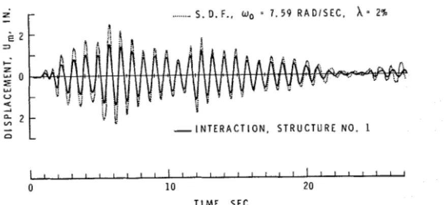
2% E 2 3 C U - I N T E R A C T I O N , S T R U C T U R E N O . 1 L I I I 1 ~ I ~ ~ ~ ' ~ l l l ~ l ~ l l ' ' ' ' ' " ~ 0 1 0 2 0 T I M E . S E CFIG. 4.-RELATIVE DISPLACEMENT RESPONSE FOR STRUCTURE NO. 1 SUB- J E C T E D T O E L CENTRO 1940. N-S COMPONENT
r
- ....-
S. D. F..a =
7 . 6 0 R A D I S E C , = 2% k 3 C 5 05
0 4 2-
2 YI-
- I N T E R A C T I O N , S T R U C T U R E N O . 2 a I I I I ~ ~ ~ I I ~ ~ I ~ ~ I ~ I I ~ ' ' ~ I ~ I I I ~ 0 1 0 20 T I M E , S E CFIG. 5.-RELATIVE DISPLACEMENT RESPONSE FOR STRUCTURE NO. 2 SUB- J E C T E D T O E L CENTRO 1940, N-S COMPONENT
r e s p o n s e s for S t r u c t u r e s No. 1 and 2, with their p a r a m e t e r s a s given in Table
1. The base disturbance consists of 27 s e c of the r e c o r d of the El Centro, California, 1940 earthquake, N-S component. F o r Structure No. 1 the solid line in Fig. 4 r e p r e s e n t s the response of the interaction system, obtained by the F o u r i e r t r a n s f o r m method with Eq. 14 used a s the t r a n s f e r function. The dotted line r e p r e s e n t s the response of an SDF system with natural frequency S2 = 7.59 r a d p e r s e c and interstory damping A = 2
%.
The interaction r e -sponse using the equivalent SDF with w , = 7.59 rad p e r sec,
( w , / w , ) ~
= (7.59/ 10.0)2 = 0.576, and X, = 1.37'%
gives r e s u l t s that a r e indistinguishable from the t r u e interaction response throughout the full 27 sec. The SDF response was obtained by a numerical integration procedure ( 8 ) .Similar calculations for Structure No. 2 a r e presented in Fig. 5. The solid line represents the interaction response obtained by numerical integration using the equivalent SDF model shown in Table l b . The dotted curve again r e p r e s e n t s the relative displacement for the SDF with X = 2
'%
and D = 7.60r a d p e r sec.
PARAMETER STUDY
A parameter study has been c a r r i e d out with the two ranges of p a r a m e t e r s shown in Table 2 to examine the behavior of the interaction system. Poisson's ratio v and density of the ground p have been kept constant a t z e r o and 120 lb p e r cu ft, respectively. A variation in the two p a r a m e t e r s would be reflected primarily in changes in the s h e a r wave velocity V , and the rocking stiffness
k + , both of which a r e variables in this study.
P a r a m e t e r S e t A . - P a r a m e t e r Set A, Table 2 , includes s t r u c t u r e s such a s elevated storage tanks and water towers and other tower s t r u c t u r e s that can be idealized a s a lumped m a s s supported by a spring.
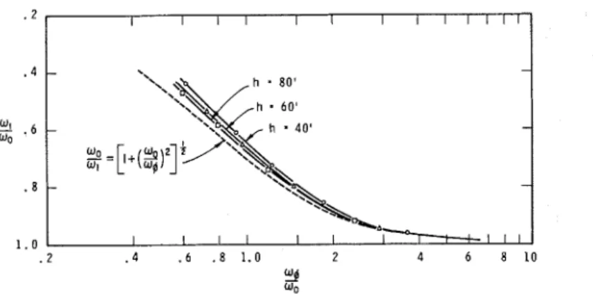
Reduction of Resonance Frequency.-For P a r a m e t e r Set A, Table 2 , the reduction of resonance frequency for the interaction system i s shown in Fig.
6. The ordinates indicate the reduction in resonance frequency relative to fixed-base frequency, whereas the abscissa i s the ratio of static rocking fre- quency to the fixed-base natural frequency. Rocking frequency
in which k+ = 8 G r 3 / [ 3 ( 1
-
v ) ] = rocking stiffness of circular plate under static conditions and I = total moment of inertia = m , h 2+
m 1 ( r Z / 4 )+
m 0 ( r 2 / 4 )for the c i r c u l a r configuration of top and bottom mass.
The lower, heavier curve in Fig. 6 corresponds to the theoretical relation of frequency reduction for a single-story building, considering only rocking and relative displacement ( 7 ) . This curve a l s o establishes the theoretical lower bound for fundamental frequency reduction of the three-degree-of- freedom interaction system. Actual values of frequency reduction for the aforementioned ranges of P a r a m e t e r Set A, Table 2 fall within the region bounded by the two curves.
Magnitudes of Resonance Peaks.-In addition to the factor wl/wo, the other p a r a m e t e r required for a complete quantitative description of the equivalent SDF model i s the equivalent damping ratio A,. F o r particular structural pa- r a m e t e r s and foundation properties, X, may be found from a p a r a m e t e r study of resonance amplitude peaks and Eq. 2. Detailed r e s u l t s a r e presented f o r the Bycroft foundation model and a foundation having constant stiffness and damping coefficients.
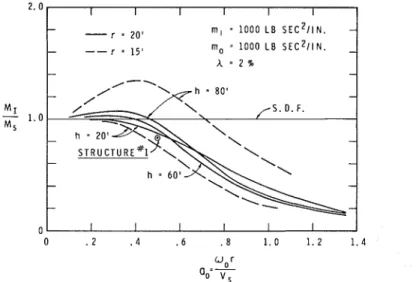
Bycroft Foundation Model.-For the foundation properties presented in
Fig. 3 , Figs. 7 and 8 show the ratio of peak amplitudes MI of the frequency response curve for the interaction system to the peak amplitudes
M S
of the SDF, fixed-base system. The abscissa i s a, = w 0 r / v , , in which wo = naturalEM 5 STRUCTURE-GROUND INTERACTION 1441 frequency of fixed-base s t r u c t u r e . T e r m s M I and M S r e p r e s e n t therelative displacements Um a t the resonance frequency il = w,.
With s m a l l values of a, it may be seen f r o m Figs. 7 and 8 that f o r tall s t r u c t u r e s the peak amplitude of the frequency response curve exceeds that of a n SDF s y s t e m with the s a m e amount of s t r u c t u r a l damping. In o r d e r to in- t e r p r e t some influences of the foundation p r o p e r t i e s i t i s useful to r e f e r to the
TABLE 2.-RANGES O F PARAMETERS
- - -
Variable P a r a m e t e r s e t A
(1) (2)
FIG. 6.-REDUCTION IN RESONANCE FREQUENCY F O R INTERACTION SYSTEMS, PARAMETER S E T A, T A B L E 2 P a r a m e t e r s e t B (3) w,, in r a d i a n s p e r second m,, in pounds p e r second s q u a r e d p e r inch m,, in pounds p e r second squared p e r inch h , in feet r , in feet A , a s a percentage V,, in feet p e r second
SDF stiffness and damping t e r m s presented in Fig. 3 . It may be observed that in the rocking mode the foundation damping coefficient for s m a l l values of a is practically zero; therefore, the l a r g e values of peak resonance amplitudes a r e not unexpected.
The curve for h = 20 ft in Fig. 7 exhibits behavior slightly different from that f o r taller s t r u c t u r e s . T h i s i s due to the increased influence the hori-
5 to 20 1,000 to 4,000 1,000 20 to 80 1 5 and 20 1, 2, and 5 300, 500, and 800 5 to 20 100,000 and 400,000 100,000 and 400,000 40 to 80 60 2 500, 800, and 1600
FIG. 7.-MAGNITUDES O F PEAK RESONANCE CURVES FOR RELATIVE DISPLACE- MENTS, m = 1,000 L B SEC SQUARED P E R IN., BYCROFT FOUNDATION
1
FIG. 8.-MAGMTUDES O F PEAK RESONANCE CURVES FOR RELATIVE DISPLACE- MENTS, m = 4,000 L B SEC SQUARED P E R IN., BYCROFT FOUNDATION
STRUCTURE-GROUND INTERACTION
FIG. 9.-MAGNITUDE O F PEAK RESONANCE CURVES FOR RELATIVE DISPLACE- MENTS, rn = 4,000 L B SEC SQUARED P E R IN., A = 1 '% AND 5 '% BYCROFT
1 FOUNDATION I I I I I I - m , = 4 0 0 0 L B S E C ~ I I N . - m, = 1 0 0 0 L B S E C ~ I I N . - - r = 2 0 ' - A - 2 % - - C O N S T A N T F O U N D A T I O N - S T I F F N E S S A N D D A M P I N G - - d
FIG. 10.-MAGNITUDES O F RESONANCE PEAKS FOR RELATIVE DISPLACEMENTS, m = 4,000 L B SEC SQUARED P E R IN., CONSTANT SDF FOUNDATION STIFFNESS
1
zontal b a s e motion a s s u m e s for s t r u c t u r e s with small height-to-width ratios. F o r taller s t r u c t u r e s rocking predominates, s o that a l l curves will be mainly influenced by the damping curve for rotation,
C R ,
shown in Fig. 3. Conse- quently, a l l c u r v e s in Fig. 7 for the t a l l e r s t r u c t u r e s can be expected to have the s a m e general shape. In Figs. 8, 9, and 10, this different behavior f o r h =20 ft i s not in evidence, because top m a s s m , i s four times a s l a r g e a s that in Fig. 7. This i n c r e a s e s the moment of inertia and again r e s u l t s in a predomi- nance of rocking over horizontal b a s e motion, even for h = 20 ft.
The effects of varying interstory damping a r e demonstrated in Fig. 9 f o r
A = 1 % a n d 5
%,
using the Bycroft foundation p a r a m e t e r s in Fig. 2. The gen- e r a l variation of peak amplitudes i s s i m i l a r , although the values f o r A = 5%
a r e l a r g e r . This may be explained by r e f e r r i n g to the
CR
curve in Fig. 3. F o r a given value of a o r a,, foundation damping r e p r e s e n t s a s m a l l e r proportion of the overall system damping f o r A = 5%
than for A = 1%.
Consequently, the ratio of resonance p e a k s M I / ~ s for a given value of a, can be expected to be l a r g e r for the higher values of interstory damping.Constant Foundation Parameters.-An assumption frequently adopted in
investigating the effects of foundation flexibility i s that stiffness and damping p r o p e r t i e s a r e independent of frequency. Such an approximation i s shown in Fig. 3 by the dash-dotted lines. The p a r a m e t e r study f o r the ratio MI/uS, using constant foundation p a r a m e t e r s , i s shown in Fig. 10. I t m a y be seen that the peak values in the range of small a, have been substantially reduced in comparison with the peaks f o r the frequency-dependent foundation p a r a m e t e r s shown in Fig. 8.
This would be expected because with s m a l l e r values of a, m o r e damping i s present in the rocking motion under the constant approximation than f o r the frequency-dependent case. The effect of the approximation, however, on the reduction of natural frequency i s quite small. F o r the p a r a m e t e r range studied the l a r g e s t i n c r e a s e in the fundamental resonant frequency over the c a s e with frequency-dependent p a r a m e t e r s i s 4
O/o
and occurs for w,r/Vs =0.35. The deviations d e c r e a s e f o r s m a l l e r valuesof w,r/Vs. F o r this approx- imation of constant foundation p r o p e r t i e s the bounds for frequency reduction in Fig. 6 a r e therefore s t i l l valid.
P a r a m e t e r Set B . - P a r a m e t e r Set B, Table 2 corresponds to s t r u c t u r e s such a s nuclear r e a c t o r containment vessels.
Reduction of Resonance Frequency.-The reduction of resonance frequency f o r P a r a m e t e r Set B i s shown in Fig. 11. The s a m e abscissa andordinate a r e chosen a s f o r P a r a m e t e r Set A. Frequency reductions a r e l a r g e r than those for Set A shown in Fig. 6 owing to the increasing influence of the relative horizontal b a s e displacement
U B
(for P a r a m e t e r Set A the relative b a s e dis- placement had negligible influence). A s the s t r u c t u r e becomes taller, fre- quency reductions approach the theoretical curve for frequency reduction considering base rocking only. T h i s l a t t e r curve i s shown in Fig. 11 in dashed lines.Magnitudes of Resonance Peaks.-For P a r a m e t e r Set B plots of magni- tudes of resonance peaks a r e presented in Fig. 12. The equivalent damping factor, A,, can be found therefrom, a s described previously. It may be seen that resonance peaks for a l l values of a, a r e l e s s than o r equal to those of the SDF system with the s a m e resonance frequency and interstory damping. This implies that for the s t r u c t u r a l p a r a m e t e r s considered the interstory dis- placement of the interaction s y s t e m i s l e s s than o r possibly equal to the r e -
STRUCTURE-GROUND INTERACTION 1445
FIG. 11.-REDUCTION IN RESONANCE FREQUENCY F O R INTERACTION SYSTEMS, PARAMETER S E T B, T A B L E 2 . 2 . 4 -
"'
. 6 "a . 8 1 . 0 - - m a = m l-
~ O O O O O L B S E C ~ I I N . -ma-
m~-
4 0 0 0 0 0 L B S E C ~ I I N . r = 6 0 '-
2% B Y C R O F T F O U N D A T I O N I I I I I I I I I I I I I - - h-
8 0 '-
- h.
4 0 ' - - I I I I I I I ; ! I l lFIG. 12.-MAGNITUDES O F RESONANCE PEAKS F O R RELATIVE DISPLACEMENTS, m = m = 100,000 AND 400,000 L B SEC SQUARED P E R IN., A = 2 %, BYCROFT
1 0
. 2 . 4 .6 . 8 1 . 0 2 4 6 8 1 0
FOUNDATION
sponse of the corresponding SDF system for any type of ground disturbance. Response due to Random-type Disturbances.-Note that peak amplitudes of the frequency response c u r v e s for relative displacement do not, by them- selves, give any measure of the response that may be expected from a random-type b a s e input; in the disturbance, frequency components other than those a t the resonance frequency of the s t r u c t u r e may predominate.
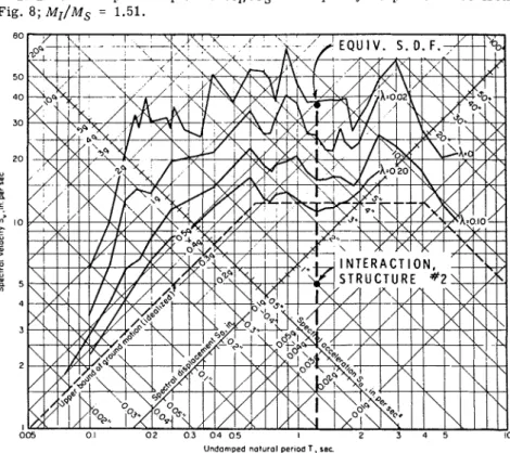
DETERMINATION O F MAXIMUM RESPONSE FROM SPECTRA With the aid of the equivalent SDF model, the maximum response for an interaction system may be determined f r o m established response spectra of
known earthquakes o r other disturbances. The procedure i s illustrated herein with Structure No. 2 , Table 1 , for the response spectrum of the El Centro,
1940 earthquake, N-S component ( l ) , shown in Fig. 13.
1. Find reduced fundamental frequency w , (either from computations out- lined previously o r from the graph in Fig. 6 ) ; w , = 7.60 r a d p e r s e c .
2. Determine peak amplitude M ~ / M ~ of frequency response curve from Fig. 8; M I / M S = 1.51.
Undamped noturol pernod T . rsc
FIG. 13.-ELASTIC RESPONSE SPECTRA, 1940 EL CENTRO EARTHQUAKE, N-S COMPONENT (1)
3 . Multiply amplitude M ~ / M ~ by ( W ~ / W , ) ~ = 6.95 and determine effective damping ratio from Eq. 2. By direct proportionality with the amplitude for h = 2 %
1
A, = (0.02)
i1.51)(6.95)
= 0.00192 = 0.192%
.
. .
. . .
.
( 1 7 ) 4 . Enter response spectrum with damping ratio A, and natural frequencyw , ( o r the corresponding period T = 1.21 sec) and read maximum spectral response; SD
-
7 in.5. Divide s p e c t r a l value by ( W , / W , ) ~ to obtain true maximum interaction
response; maximum relative displacement
-
1 in. This value a g r e e s with the response calculation shown in Fig. 5.EM
5
STRUCTURE-GROUND INTERACTION 1447 The procedure i s only slightly more complex than that using the response spectrum for SDF systems. With the aid of the equivalent SDF model it may thus be possible to construct a modified response spectrum to account for the influence of structure-ground interaction.A useful approximation in the application of the response spectrum follows. For structures with small amounts of interstory damping (say up to 5
O/o)
the equivalent damping, A, will be small for reasonably large reductions of fre- quency, a s i s evident from Eq. 2. Consequently, the spectrum curve for zero damping can be usedand the spectral i s divided by response by ( W , / W , ) ~ . Thiswill give a conservative estimate of interstory response for all cases. The approximation will improve with smaller interstory damping and larger fre- quency reduction ratio
( w ~ w , ) ~ .
Generalization of Maximum Response Comparisons.-A general conclusion regarding the response magnitude of interaction systems can be obtained from an examination of Figs. 7 to 10 and Fig. 12, which indicate that over a considerable range of values of a, the peaks of the frequency response curves a r e smaller than those of the SDF oscillator with the same natural frequency. F o r these cases the maximum response of the interaction system i s a priori l e s s than that of the SDF case. Where the resonance peaks exceed those of the SDF case, the response of the interaction system may exceed that of the SDF oscillator, particularly under steady-state excitations with frequency close to the resonance frequency of the structure. Considering, however, the random nature of the earthquake excitation, the contributions over the whole frequen- cy response curve have to be included.
By means of a numerical summation technique it was found that the a r e a s under the frequency response curves of the interaction systems studied a r e smaller than o r equal to the corresponding a r e a s for SDF systems with the same natural frequency and interstory damping. If the disturbance i s ideal- ized a s weakly stationary, then on the basis of random vibration theory (6) it can be demonstrated that the mean relative displacement response for the in- teraction systems considered will be l e s s than o r equal to the response of an SDF oscillator with the same natural frequency. A similar conclusion for a more limited range of parameters was reached by Perelman, et al. (12) by means of response calculations with artificially generated earthquakes. F o r any particular interaction structure anda given base motion this can be veri- fied with the aid of the equivalent SDF model and the response spectrum.
CONCLUSIONS
A method of analysis i s presented that utilizes the transformation of a single-story interaction structure into an equivalent SDF model to determine the response of interaction systems under earthquake-type disturbances. The equivalent SDF model permits the use of numerical integration and response spectrum techniques in determining relative displacements. This approach avoids some of the drawbacks of previous studies in which either a random- type o r a steady-state disturbance was used alone.
From an extensive parameter study it i s shown that for tall slender struc- tures the most important interaction parameter i s the ratio of rocking fre- quency of the structure to its fixed-base natural frequency. This ratio permits the simple determination of the natural frequency of the interaction
s t r u c t u r e , the constant multiplication factor f o r conversion to the equivalent SDF model, and the equivalent damping ratio.
F o r massive s t r u c t u r e s with a low height-to-base ratio, the relative b a s e displacement a s w e l l a s rocking motion influence the frequency reduction, and consequently the ground-structure interaction e f f e c t s a r e also influenced significantly.
F r o m a study of resonance peak amplitudes i t i s shown that under steady- s t a t e disturbances the interstory displacement of the interaction s t r u c t u r e can b e l a r g e r than that for an SDF with the s a m e resonance frequency and interstory damping. T h i s i s the c a s e f o r tall slender s t r u c t u r e s and for val- ues of the nondimensional frequency a, up to about 0.6 with the Bycroft foun- dation. In contrast, for interaction s t r u c t u r e s under random-type excitations the interstory displacement can b e expected to be equal to o r l e s s than that f o r an SDF oscillator with the s a m e natural frequency and interstory damping.
ACKNOWLEDGMENT
T h i s paper i s a contribution from the Division of Building Research, Na- tional Research Council of Canada, and i s published with the approval of the Director of the Division.
APPENDIX I.-REFERENCES
I. Blume, J . A , , Newmark, N . M., and Corning, L. H., Design o j Multistory Reinjorced Concrete
Buildings jor Earthquake Motions, Portland Cement Association, Chicago, Ill., 196 1 .
2. Bycroft, G . N., "Forced Vibrations of a Rigid Circular Plate on a Semi-Infinite Elastic Space and on an Elastic Stratum," Philosophical Transactions. Royal Society, London, England, Series A, Vol. 248, No. 948, Jan., 1965, pp. 323-368.
3. Castellani, A,. "Foundation Compliance Effects on Earthquake Spectra," Journal o j the Soil
Mechanics and Fo~tndations Division. ASCE, Vol. 96, N o . SM4, Proc. Paper 7425, July 1970,
pp. 1335-1355.
4. Harris, C. M., and Crede, C . E., ed., Shock and Vibration Handbook. Chap. 23. McGraw- Hill Book Co., New York, 1961.
5. Kobori, T., Minai, R., and Suzuki, T., "Dynamical Characteristics of Structures on an Elastic Ground," (In Japanese) Kyoto University, Disaster Prevention Institute, Annual Report No. 9. Mar., 1966. pp. 193-224.
6. Lin, Y. K., Probabilistic Theory o j Structural Dynamics. Chap. 5 , McGraw-Hill Book CO., New York, 1967.
7. Merritt, R. G., and Housner, G. W., "Effect of Foundation Compliance on Earthquake Stresses in Multistory Buildings," Bulletin, Seismological Society of America, Vol. 44, NO. 4, Oct., 1954, pp. 55 1-570,
8. Newmark, N. M., "Method of Computation for Structural Dynamics," Journalojthe Engineer-
ing Mechanics Division, ASCE, Vol. 85, No. EM3, July 1959, Proc. Paper 2094, pp. 67-94.
9. Parmelee, R. A,, "Building-Foundation Interaction Effects," Journal o j the Engineering Me-
chanics Division. A S C E , Vol. 93, No. EM2, Proc. Paper 5200, April, 1967, pp. 131-152.
10. Parmelee, R . A,, et al., "Seismic Response of Structure-Foundation Systems," Journal o j the
Engineering Mechanics Division. ASCE, Vol. 94, No. EM6, Proc. Paper 6264, Dec.. 1968, pp.
1295-1315.
EM 5 STRUCTURE-GROUND INTERACTION 1449
tures on Flexible Foundations." Bullerin. Seismological Society of America, Vol. 59, No. 3,
June, 1969, pp. 1061-1070.
12. Perelman, D. S., Parmelee, R. A,, and Lee, S . L., "Seismic Response of Single Story Interaction Systems," Journal of the Strucrural Division. ASCE, Vol. 94, No. S T I I , Proc. Paper 6235, Nov., 1968, pp. 2597-2608.
APPENDIX 11.-NOTATION
The following symbols a r e used in this paper:
A = dynamic stiffness for horizontal displacement on half space;
a = p r / V , = nondimensional frequency;
a , = w , r / ~ , = nondimensional SDF resonance frequency;
B = dynamic rocking stiffness on half space;
C H , CR = SDF damping coefficients for horizontal and rocking dis- placements, respectively;
c = interstory damping coefficient;
f l ~ , f z ~ ,
f l R , f zR = variables for steady-state dynamic behavior of weightless
d i s c on elastic half space for horizontaland rocking motion; G = s h e a r modulus of ground;
g = subscript denoting ground; h = s t o r y height;
I = I,
+
I, = total moment of inertia, a l s o subscript designating inter- action s y s t e m ;I, = moment of inertia of top and bottom m a s s ;
I, = second moment of m a s s m , about b a s e = m , h Z ;
K H , K R = SDF stiffness coefficients f o r horizontal and rocking dis- placements, respectively;
k = s t o r y stiffness;
k a = static rocking stiffness;
M , M , = moment on b a s e under a r b i t r a r y and steady-state motion, respectively;
M e = peak magnitude of frequency response for equivalent SDF model;
M I , M S = peak magnitude of frequency response for interaction sys- tem and SDF oscillator, respectively;
m , = b a s e m a s s ;
m , = top m a s s ;
P,
Po
= horizontal force on b a s e under a r b i t r a r y and steady-state motion, respectively;p
= frequency, in radians p e r second; r = radius of base;S = subscript designating SDF system;
SD
= s p e c t r a l displacement;T = period, in seconds;
T$
-
= t r a n s f e r function for displacement vector d and ground dis-U B
= total b a s e displacement of interaction system;U R
--
= total displacement of top m a s s of interaction system;U,
= relative interstory displacement of interaction system o r SDF s y s t e m ;ug, iig = steady-state ground displacement and acceleration, r e - spectively;
u = relative horizontal displacement of b a s e m a s s with respect to free-field ground motion;
V,
= s h e a r wave velocity of ground;W = amplitude of steady-state ground disturbance;
X , Y, Z = complex amplification f a c t o r s f o r b a s e displacement, rock- ing and interstory displacement, respectively;
a = m,/ml = m a s s ratio;
,!
3 = m l / p r 3 = nondimensional top m a s s ;
q = ( h / ~ ) ~ = aspect ratio squared;
X = relative interstory damping ratio;
AH, XR = relative damping ratios f o r horizontal and rocking motion, respectively, of b a s e m a s s ;
A, = equivalent SDF damping ratio;
v = Poisson's r a t i o of ground;
p = m a s s density of ground;
+
= angular variable, in radians;A2 = natural frequency of SDF oscillator, in radians p e r second; W H = resonant frequencies of d i s c on elastic half space for hori-
zontal motion, in radians p e r second;
w~ = I, = m l h = resonant rocking frequency f o r c i r c u l a r s t r u c t u r e with mo-
ment of inertia, in radians p e r second;
w, = ( k / m l ) 1 / 2 = natural frequency of fixed-base s t r u c t u r e , in radians p e r
second;
wl = fundamental frequency of interaction system, in radians p e r second; and
This publication is being distributed by the Division of Building Research
of the National Research Council of Canada. It should not be reproduced
in whole or in part without permission of the original publisher. The Divi-
sion would be glad t o be of assistance in obtaining such permission.
Publications of the Division may be obtained by mailing the appropriate
remittance (a Bank, Express, o r Post Office Money Order, o r a cheque,
made payable t o the Receiver General of Canada, credit N R C ) t o the
National Research Council of Canada, Ottawa. KIAOR6. Stamps are not
acceptable.
A list of all publications of the Division is available and may be obtained
from the Publications Section, Division of Building Research, National
Research Council of Canada, Ottawa. KIAOR6.
I
8422 STRUCTURE-GROUND INTERACTION IN EARTHQUAKES I k
KEY WORDS: dynamics; earthquakes; clasticity; engineerin mechanics; faun-; r - t r - a n a l y s i s ; s t r t c t u r a l
engineering; vibration I
ABSTRACT: A method of analysis i s presented for determining elastic structure- ground interaction effects of single-story s t r u c t u r e s under earthquake loads. The method derives a n equivalent SDF model for the relative story displacement, in- corporating the effects of horizontal and rotational base flexibility i n a structure. ,
The equivalent SDF model then permits t h e determination of t h e seismic inter- action response directly f r o m established o r assumed response s p e c t r a , o r f r o m response calculations of ordinary SDF systems. Sample calculations a r e pre- sented showing responses f o r the interaction system, the equivalent SDF model, and a n SDF system with the s a m e natural frequency a s the interaction structure. A study of a wide range of p a r a m e t e r s under earthquake-type disturbances establishes that for the interaction systems considered interstory displacements a r e reduced in relation to an SDF s y s t e m with identical fundamental frequency and interstory damping.
REFERENCE: Rainer, Johann H., "Structure-ground Interaction in Earth- I 1
quakes," Journal of the Engineering Mechanics Division, ASCE, Vol. 97, NO. I I