Publisher’s version / Version de l'éditeur:
Technical Translation (National Research Council of Canada), 1967
READ THESE TERMS AND CONDITIONS CAREFULLY BEFORE USING THIS WEBSITE.
https://nrc-publications.canada.ca/eng/copyright
Vous avez des questions? Nous pouvons vous aider. Pour communiquer directement avec un auteur, consultez la première page de la revue dans laquelle son article a été publié afin de trouver ses coordonnées. Si vous n’arrivez pas à les repérer, communiquez avec nous à [email protected].
Questions? Contact the NRC Publications Archive team at
[email protected]. If you wish to email the authors directly, please see the first page of the publication for their contact information.
NRC Publications Archive
Archives des publications du CNRC
For the publisher’s version, please access the DOI link below./ Pour consulter la version de l’éditeur, utilisez le lien DOI ci-dessous.
https://doi.org/10.4224/20386698
Access and use of this website and the material on it are subject to the Terms and Conditions set forth at
Vented cast stone facings for buildings
Kopatsch, H.
https://publications-cnrc.canada.ca/fra/droits
L’accès à ce site Web et l’utilisation de son contenu sont assujettis aux conditions présentées dans le site LISEZ CES CONDITIONS ATTENTIVEMENT AVANT D’UTILISER CE SITE WEB.
NRC Publications Record / Notice d'Archives des publications de CNRC:
https://nrc-publications.canada.ca/eng/view/object/?id=b0aea0f1-923a-4f6a-b0ee-b02279a936ec https://publications-cnrc.canada.ca/fra/voir/objet/?id=b0aea0f1-923a-4f6a-b0ee-b02279a936ec
With the recent trend towards lighter exterior walls thermal
considerations in design and construction are セ。ゥョゥョセ increasing
importance. Condensation on interior surfaces as well as inside the
wall itself can significantly reduce the satisfactory performance of such walls.
Although Canada has, because of its climate, already achieved a
considerable degree of maturity in dealing with these thermal ーイッ「ャ・ュセ
it is interesting to study the approach used in other countries in
dealing with thermal and moisture problems in walls. It is for this
reason that the Division of Building Research arranged to have this article
by
H.
Kopatsch translated. The article is about the use of vented casestone facings for buildings and describes German practices, refers to pertinent German DIN specifications and presents certain recommendations for such claddings.
The Division wishes to record its thanks to
W.R.
Schriever, Headof its Building Structures Section,for エイ。ョウャ。エゥョセ this paper, and to
the Translations Section of the National Research Council with whose co-operation this translation is being produced.
OTTAWA
September,
1967
N.B. Hutcheon Assistant Director
NATIONAL RESEARCH COUNCIL OF CANADA
Technical Translation 1301
Title: Vented cast stone facings for buildings
(Beluftete Fassadenkonstruktionen mit Betonwerkstein)
Author: H. Kopatsch
Reference: b・エッョウエ・ゥョMz・ゥエオョセL 30 (3): 109-116, 1964
Translator: W.R. Schriever, Division of Building Research, National
Introduction
The development in the field of 「オゥャ、ゥョセ エ・」ィョッャッセケ and structural
・ョセゥョ・・イゥョァ in modern buildings has led to a much ィゥセィ・イ exploitation of the
strengths of the various materials and consequently to thinner members in
load 「・。イゥョセ walls and exterior walls. Load 「・。イゥョセ exterior walls have
become rather thin. This is even more the case with non-load bearing exterior
walls which, as infill walls and curtain walls in framed construction are now made as thin as possible in order to reduce weight and thus to derive the
greatest economic 。、カ。ョエ。セ・N The structural requirements of a 「オゥャ、ゥョセ or a
building element are, however, not the only ones to be considered. There are
a number of other important requirements to fulfill which relate predominantly
to climatic effects and the use of the building. Thicknesses of exterior walls
in building constructions of 50 cm (20 in.) or more were common until a few
decades 。セッN These walls were structurally greatly ッカ・イM、・ウゥセョ・、[ from the
point of view of a healthy indoor climate such walls,especially when built of
soild masonry, were very satisfactory. The present trend towards reduction
of the wall thickness to the bare minimum means that many of the walls do not
always satisfactorily fulfill all physical requirements. The obvious solution
to the problem is the use of a multi-layer wall structure in which each layer fulfills a separate function.
So far it has been common in building practice to consider the thermal resistance of elements in the steady state condition as a measure for their
thermal behaviour. The behaviour of building materials and 「オゥャ、ゥョセ elements
from a thermal and moisture point of view have such an influence on each other, however, that the separate treatment of one of these factors alone
leads to an unsatisfactory result. This is true particularly in multi-layer
wall construction as will be shown.
Performance Requirements for Exterior Walls
Exterior walls in addition to structural loading are subjected in the main to the following forces:
1. Thermal forces due to solar radiation and temperature 」ィ。ョセ・ウ from warm
to cold.
2. Moisture effects due to 、イゥカゥョセ rain.
3.
Moisture effects from the inside due to water vapour diffusion andMセM
Thermal effects
The exterior faces of 「オゥャ、ゥョセウ are subjected to daily and yearly
temperature cycles and· the イ・ウオャエゥョセ ャ・ョセエィ changes or stresses.
The surface temperature of a body subjected to solar radiation depends
in the first instance on the ー・イ」・ョエ。セ・ of the total received radiation
energy which is transformed into heat at the surface. Other factors involved
in the resulting surface temperature are the influence of the conductivity of the surface, the temperature and movement of the surrounding air, the temperature and surface of any other bodies in contact with the considered
surface and the thermal properties of the body itself and any back-up materials. A highly insulated wall material of small conductivity produces a thermal
barrier for the exterior cladding.
Tests on the temperatures of typical surfaces under the influence of
solar radiation and the loss by radiation 、オイゥョセ the night are described by
K.
SChropp(l), which indicate marked dependence of the temperature on thecolour of the surfaces.
The greatest over temperatures compared to the ambient air temperature were obtained for black surfaces, the smallest for white surfaces and for
shiny aluminum foil. In contrast to the temperature increases under solar
radiation, it was found that the temperature difference at night, イ・ウオャエゥョセ
from long wave radjation to the sky, was almost the same for the white surface
as for the black. The behaviour of white surfaces under the influence of
solar radiation is explained by Schropp by the dependence of the absorption conditions on the type of received radiation energy, that is, on the
wave-ャ・ョセエィ of the radiation, or in the fact that it is much smaller for short
wave radiation than for long wave radiation.
Reiher(2) also emphasizes the influence of the colour on the temperature
variations and therefore on the ャ・ョセエィ variations of wall materials which are
subjected to solar radiation.
According to SchUle(3), walls facing east-south-east and west-south-west receive the greatest radiation in the months May, June and July, whereas the walls facing south receive the maximum for the other months.
In the construction of exterior stone facings the effects of thermal loads must be considered in the construction requirements such as to reduce
the resulting stresses to a minimum. The specification DIN 18,333, Cast
Stone Construction, does not contain any requirements in this regard. On the
type of attachments, clause SNセR specifies the ヲッャャッキゥョセZ Each niece of the
cladding must be anchored to the backup material in such a way that it will
be completely secure. Unless otherwise specified in the contract, each piece
In this requirement for a mortar joint we find contained a general desire
to create a vented zone behind the cladding. It is, however, not explicitly
said that the mortar strip should be interrupted and should not run
con-tinuously over the full height and width of the building. Furthermore there
is no indication in DIN 18,333 of the desirability of making the 」ャ。、、ゥョセ
envelope flexible in order to reduce the stresses. As an ・ク。ューャセ a
calcula-tion of the stresses will now be made for a given set of boundary condicalcula-tions.
a) Monolithic installation. As a basis of the calculation we shall
use the temperature gradient indicated in Figure 5. It will be assumed that
°
the 」ャ。、、ゥョセ was installed at a temperature of 25 C and that the cladding and
the back-up wall had the same temperature. The thermal expansion coefficient
of concrete according to Graf(4) depends largely on the type of aggregate. In DIN 1045, paragraph 16, it is indicated for use in building purposes as follows:
-6
°
at = 10 x 10 / C.
The increase of temperature over the mean value of the back-up wall is
64 - 41 = 24°c. The resulting strain is
-6
4
4
-4E
t
=
10 x 10 x 2=
2. x 10if we assume furthermore as a favourable condition that the back-up wall has
already come to a stable condition so that no stresses result from ウィイゥョォ。セ・
and creep which would be transmitted to the cladding. Then the stresses
from the above difference in strain between the cladding and the wall is calculated according to Hook's law with a modulus of elasticity for concrete according to Graf(5)
E
= 1.7+
(360 (for w b 28 = 300 kg/cm 2) a = 2.4 x 10-4 x 2.6 X 105 = 62.4 ォセO」ュRNb) Elastic or open joints. This compressive stress in the cladding is
even higher when the shrinkage and creep of the wall is not complete at the time of the installation of the cladding.
For a slab length of 50 cm the strain is calculated as
-6
4
4
-21 = 10 x 10 x 2 x 500 = 2. x 5 x 10 = 0.12 mm.
The joint between slabs is reduced as a result of this by 0.12 mm. If we now
consider shrinkage and creep effects of the wall behind of 0.4 mm/m then the
joint between the cladding slabs is reduced by 0.12 x 0.2 = 0.32 mm. An
-6-obviously in leaving the joints open and to prevent the ingress of driving
rain by means of stepped joints. Under the condition that the cladding stones
are mortared in strips, whereby the mortar strips must also be interrupted, it is possible in this solution to ensure that the strain is reduced to the value of the strain of a single stone and that therefore an addition of the
strain increase and the resulting ーイッセイ・ウウゥカ・ stress in the cladding is
avoided.
The maximum strains which can be tolerated by strips of mortar have been
investigated for a number of cases. In order to make the test more simple,
the wall to which the cladding had been fastened was shortened in a loading
test (see Figure 7).
Figures 7a-c show the shortening up to the destruction of the bond. Driving Rain
The DIN standards do not contain any definite instructions regarding the effects of driving rain on buildings and oreventative measures against it.
Brocker(6) proposes the following definition of dri vim; rain : "Driving rain
is precipitation (rain) combined with wind of at least speed
5
in the Beaufortscale. Heavy driving rain is precipitation (rain) combined with wind of
speed
8."
For wind speeds of
5
and up, the angle of rain impingement exceeds45°.
Pohl(7) has stated that it is not the kinetic energy of the rain drops but the absorption properties of the wall that are most important.
Even under very high wind speeds the イ・ウオャエゥョセ water pressure on the
wall surfaces exposed to driving rain is very small as shown by the following values: Wind Speed km/h m/sec Stagnation Pressure mm (H20) kg/cm2 50 65 102 140 13.9 18.0 28.3 39.0 12 20 50 95 0.012 0.020 0.050 0.095
The importance of the wind in driving rain lies in the fact that it
produces a "water film" on the outer surface of the wall. Free-standing and
especially high buildings which are not sheltered by other buildings - a frequent occurrence in our modern type of wellspaced high rise buildings -are especially subject to the effects of driVing rain.
In order to satisfy the requirements of comfort and health in living quarters it is necessary to try to keep the exterior wall materials as dry
reduced considerably.
In セ・ョ・イ。ャ the capacitv to insulate is denendent on the norosity and
nature of the pores of the wall material. Since the water tends to fill these
pores and since water conducts heat 25 times as much as air, the adverse
effect of higher wall moisture contents is obvious. It is therefore important
to provide a sufficient exterior protection against 、イゥカゥョセ rain in order to
prevent an increase of the moisture content of the wall material. Moist walls
in living quarters are frequently the source of illness and very often lead to damage to the building itself as well as to household effects, and not
least there are economic disadvantages since with ゥョ」イ・。ウゥョセ moisture content
of building materials conductivity セッ・ウ un and therefore the fuel consumntion
for heating purposes.
The requirements of DIN 4108 (Thermal Requirements for Buildings) are
limited in the main to minimum requirements of insulation for three climate
zones. The basis for this division into zones was found in local exnerience
in the individual areas with their traditional 「オゥャ、ゥョセ types, as well as
climate data. Using the minimum values of insulation calculated from these
requirements, condensation is usually not a narticular nroblem under normal
boundary conditions, provided the ゥョウオャ。エゥョセ capacity of the wall material
used in the calculation is actually available and has not been reduced by
increased wall moisture The change of the thermal resistance with increasing
In section 7.11 it is merely stated, among
moisture content and the resulting 」ィ。ョセ・ in conductivity is illustrated in
the ヲッャャッキゥョセ table (measurements of Schmidt and Grossmann).
Table I
Conduction coefficients as function of the moisture content of the wall
Solid brick wall, immediately after construction 1.20 kcal/m hOC
Solid brick wall, three months old 1.00 kcal/m hOC
Solid brick wall, dry, twelve months old 0.75 kcal/m hOC
DIN 4108 does not contain any concrete suggestions or measures to safe-guard the thermal insulation.
other things:
"Exterior walls which are made of non-frost resistant or from rather
porous absorptive materials, have to be protected on the outside 。セ。ゥョウエ
penetration by water, by a water repellent stucco, or by other adequate weather
-8-or equivalent buildintS materials."
Exterior claddings commonly used in the old days, eSDecially on timber frame houses with masonry infills and on gable ends, with wood shingles, slate and metal plates, stem from the same desire to improve the resistance atSainst drivintS rain and was technically correct since this construction did not
block vapour diffusion エィイッオセィ the wall and since thermal stresses and to
some extent also movements of the building could be accommodated by this layer, althoutSh certain disadvantages with regard to durability, health and aesthetics had to be accepted.
In drivintS rain, intensity and frequency as well as predominant wind
direction vary from place to place. fゥセオイ・
9
tSives some indication on thedriving rain intensity and frequency for three representative cities. It will
be seen from this that driving rain effects on exterior walls are not limited to the north German lowlands.
Wind LoadintS. Wind loading is an essential factor when considerintS
the structural frame In addition to this, however, elements of the wall
must also be built to resist the wind loads without 、。ュ。セ・N The wind loads
are given in DIN 1055, Load Assumptions for Buildings, sheet 4. The wind
direction can, in tSeneral, be assumed to be horizontal. The wind load which
is composed of a pressure and suction effect, is,
The coefficient c depends on the shape of the building and can be assumed to
be 1.2 for a closed 「オゥャ、ゥョセ with plane surfaces at right angles to the wind.
Taale II
Stagnation pressure of wind loads with shape
coefficient of c = 1.2
Height of BuildintS Stagnation Pressure Wind Load for
m kg/m2 c
=
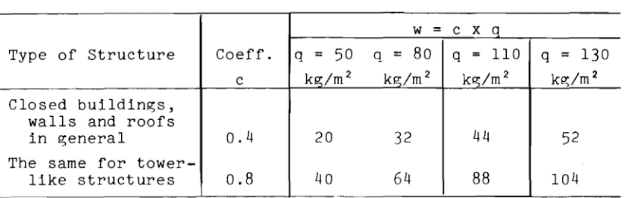
1.2 kg/m2_ From 0 to 8 50 60 From 8 to 20 80 96 From 20 to 100 110 132 Over 100 130 156For closed buildings with a rectangular plane the wind load can be assumed to be composed of a pressure of +0.8 q and a suction of -0.4 q for the
main frame. Walls, roofs and other building elements have to be safeguarded
depend on the type of 「オゥャ、ゥョセN
Table III
Coefficients c and suction w per unit of area
w
=
c xqType of Structure Coeff. q =
50
q=
80
q=
110
q=
130
c kg/m 2 kg/m 2 ォセOュR kg/m 2
Closed buildings, walls and roofs
in general
0.4
20
32
44
52
The same for
tower-like structures
0.8
40
64
88
104
DIN
1055
also states that along the intersections of wall and roofsur-faces the suction can be much higher than the above calculations indicate. All building elements therefore have to be fastened very carefully in such areas.
Moisture effects from the interior caused by vapour diffusion and
condensation. The vapour diffusion as a further criterion of building physics
will be treated here only in a general way and only to the extent to which this is necessary for the evaluation of the advantage of a ventilated exterior
cladding. Ordinary household activities produce water vapour (cooking,
washing, breathing). Like all other gases water vanour in the air, as a
result of molecular movement, has a desire to even out density differences.
This phenomenon is called diffusion. Since furthermore water vapour density
and water vapour pressure are proportional, the diffusion can also be regarded
as an equalization of pressure, the vapour movement 、・ー・ョ、ゥョセ on the pressure
differences. A pressure difference also exists when, in spite of the same
vapour density, different temperatures are present, since the vapour pressure
increases with the temperature. As a result,vapour movement will take place.
Apart from the pressure difference between the two sides of a building element, the specific vapour permeability of the building material is of importance
in considering vapour movement. This property of the material is called
diffusion resistance factor and is a measure of how much the diffusion resist-ance of the building material considered exceeds that of a layer of air of
the same thickness. The amount of water vapour migrating through the material
-10-composition as well as its moisture content. The amount of water vapour
セッゥョァ through can be expressed as the product of the vapour pressure セイ。、ゥ・ョエ
and the diffusion coefficient. For a セゥカ・ョ material the diffusion coefficient
is clearly dependent on its 、・セイ・・ of saturation present in the inside of
the material. The ィゥセィ・ウエ values of vapour pressure which can be present at
the various points without condensation depend on the temperature distribution inside the wall.
For mUlti-layer walls the 。イイ。ョセ・ュ・ョエ of the various layers (with their
various diffusion resistances) take on an important role. The 、。ョセ・イ of
condensation is increased when the exterior of mUlti-layer walls have a
greater diffusion resistance. DIN 4108 states in section 4.12 the ヲッャャッキゥョセZ
"In multi-layered wall and roof elements inappropriate 。イイ。ョセ・ュ・ョエ of
the layers can lead to the formation of condensation which may decrease
the thermal insulation considerably. Materials which are permeable to
water vapour, located on the warm side of the wall, favour the
oenetra-tion of water vapour from the 「オゥャ、ゥョセ into the core of the walls.
Possible ways of 。カッゥ、ゥョセ formation of condensation in the 「オゥャ、ゥョセ
materials are:
4.121 - r・、オ」ゥョセ the relative humidity inside the 「オゥャ、ゥョセL ・NセN by
improved ventilation.
4.122 - iョ」イ・。ウゥョセ the vapour resistance of the warm side of walls and
」・ゥャゥョセウL ・NセN by installation of vapour barriers.
4.123 - Reduction of the vapour resistance on the cold side of the walls, e.g. by the use of materials with low vapour resistance so that
the cold side is capable of ・カ。ーッイ。エゥョセ properly."
Water vapour diffusion is not 、。ョセ・イッオウ as ャッョセ as temperature at all
points exceeds the dew-point of the vapour-air mixture. We then have an
equalization process in which an increase of the mdisture content over the
・クゥウエゥョセ equilibrium moisture content does not take place. If, however, parts
of the wall are below the dew-point temperature then condensation will take
place there. This moisture, now in its liquid form will lead to a キ・エエゥョセ
of the wall and consequently to a reduction of its thermal insulation. The
formation of condensation can be avoided by appropriate 。イイ。ョセ・ュ・ョエ of the
layers in mUlti-layered walls. The 。イイ。ョセ・ュ・ョエ of layers must ensure that
the temperature decrease inside to the outside is small at first and then greater, but however the decrease of vapour concentration is first great and
then small. Figures 12-14 illustrate the behaviour of various cross-sections
made from ャセケ・イウ with different properties.
A ventilated cast concrete 」ャ。、、ゥョセ provides the desired reduction of
slabs to the back-up material 。」」ッイ、ゥョセ to DIN
18,333,
Cast Stone Construction,section
3.42,
provides an effective ventilation of the wall construction.Open joints between the cast stone elements furthermore permit an equaliza-tion of vapour pressure on the shortest possible way.
Thermal insulation and surface temperature. Aoart from the protection
of the wall from キ・エエゥョセ by rain and the imporvement of drying of the wall
from its initial construction moisture, the ventilated cast stone cladding has
the 。、カ。ョエ。セ・ of ゥューイッカゥョセ the thermal insulation. Measurements in the
laboratory and in the field have shown that an air SDace of 1 cm provides
a thermal resistance of l/A =
0.16
m2hoC/kcal in spite of ODen joints(accord-ゥョセ to fゥセオイ・
6).
If exterior walls are constructed from a thermal point ofview 。」」ッイ、ゥョセ to the minimum requirements of DIN
4108
only, an improvementof the thermal resistance is obtained as shown in Figure
16
in percentages.The surface temperature of space-enclosing elements, consequently also
exterior walls, influences the comfort of the inhabitants. The surface
temperature depends, besides other factors (temperature difference between
both sides, interior surface resistance), on thermal resistance. An increase
of the insulation value brings about an increase of the interior surface
temperature. According to the literaturq an interior surface temperature of
16°c
is desirable to satisfy the comfort requirements of the inhabitants.fゥセオイ・ 17 shows the possible imporvements in inner surface temperature for
a wall with stone 」ャ。、、ゥョセ with a 1 cm air snace, in relation to the surface
temperatures achieved according to the DIN values and the assumed average
ヲイ・・コゥョセ temperatures in the three climate zones. Figure
18
shows the samevalues for a greater イ。ョセ・ of exterior temperatures.
Cast stone 」ャ。、、ゥョセ standards. In DIN QXセUPPL Cast Stone cャ。、、ゥョセL
Quality, Test and Application, this 」ャ。、、ゥョセ is defined as an artificial stone
which is manufactured with standard cement with natural or crushed stone
aggregates in a concrete plant according to DIN
4225, 3.
DIN4225
requiresthat a concrete manufacturing plant possesses certain installations for the
ュゥクゥョセ of concrete, protected indoor space for the manufacture of cast stone
and certain minimum transportation facilities. Concrete cast stone can be
made out of one layer of the same material or out of a core concrete with a
surface concrete (two layers). The treatment of visible surface layers is
made by means of sandblasting, キ。ウィゥョセL grinding or sanding.
Minimum requirements. Concrete cast stone must have a minimum ウエイ・ョセエィ
of
225
ォセO」ュR at age28
days. Water absorption must not exceed15
percentby volume. The quality control must be maintained by at least semi-annual
-12-Size tolerances for wall slabs are ± 1 mm in ャ・ョセエィ and width and
± 2 mm for the thickness. The pieces shall be free from any chipped edges
or other faults which ュゥセィエ impair their appearance or value.
DIN
18,333,
Cast Stone Works, requires that each piece of the cladding, except in the case of small tiles, must be anchored to the base in such away as to carry the full load by the anchors. The anchors (or clips) must
be made from steel that can be bent in the cold state and is protected against
rusting. Furthermore, unless otherwise specified, it is stated that in wall
cladding the individual pieces be set on strips of mortar. The composition
of the mortar must be appropriate to the application and type of cast stone cladding.
Summary
Cast stone has a number of specific advantages such as high strength, resistance to ageing, variable surface texture and colouring, the ability to perform structural functions if it is suitably reinforced, and some scope for
mOUlding it into various shapes. In addition, when properly designed and
installed as a facing material for walls, cast stone can fulfill the
require-ments applicable to an external wall from the viewpoint of residential ィケセゥ・ョ・
and comfort. The present article deals with the conditions affecting external
walls, with special reference to thermal, wind and moisture effects.
Les produits en beton manufacture presentent une serie d'avantages
specifiques p. ex. la resistance elevee, la resistance contre les intemperies,
une structure de surface et une couleur variable, des fonctions de supports avec une armature appropriee et, dans un certain sens, des formes variables.
En plus de ces avantages, son faGonnement ingenieux lui permet de remplir
ses fonctions comme revetement des parois du point de vue de l'hygiene
d'habitation. Le present asperqu traite les proprietes d'une paroi exterieure
en prenant specialement en consideration Ie comportement thermiaue, celui au
References
1. Schropp: Die Temperaturen technischer Oberflachen unter dem Einfluss
der sッョョ・ョ「・ウエイ。ィャオョセ und der nachtlichen Austrahlung (Temperatures
of construction surfaces under the influence of solar radiation and
nocturnal heat loss by radiation). g・ウオョ、ィ・ゥエウMiョセ・ョゥ・オイL 1931.
2. Reiher: vッイエイ。セ auf internationaler b。オヲ。」ィエ。セオョセ Hannover-Messe 1963:
Warmeschutz und Feuchtigkeitsverhalten von Aussenwanden (Thermal
insulation and moisture behaviour of exterior walls. Paper presented
to the International bオゥャ、ゥョセ m・・エゥョセ at Hanover, 1963).
3.
Schule: Kurzberichte aus der Bauforschung: uョエ・イウオ」ィオョセ・ョ uber diethermische Beanspruchung von Aussenputzen (Studies of the thermal
stresses in stucco: Short reports on bUilding research).
4.
Graf: Die Eigenschaften des Betons (Properties of concrete).2. Auflage 1960. p. 188.
5.
Graf: Die Eigenschaften des Betons (Properties of concrete).2. Auflage 1960. p. 188.
6.
Brocker: Die Widerstandsfahigkeit von Aussenwanden bei b・。ョウーイオ」ィオョセdurch s」ィャ。ァイ・セ・ョ (The resistance of exterior キ。ャャウN。セ。ゥョウエ driving
rain). Dissertation 1954.
7.
Pohl: Warmedurchgangsmessungen bei Windanfall und s」ィャ。セイ・ァ・ョ (Heat flowmeasurements under wind and driving rain conditions). Dissertation 1937.
-14-j:
iッNセ ャGセk Lセ
OLセGoc Pfl"'EL セt..
セlN ᆬjiilセLN ...q ...L PfU,J,El..V '
/'
;....
,
,'_T
thU10ERセャHQセm/
1\
\ o.cves/
\
//"'0'ft.PRIlE\
/ '.1...
I1/
M
.'.'..
".
'.
\
\ I '.セ I [....'.'.
-
'. i...-
セ セGャ|QBセセ
セM
1.
"w,I J
セMZ
....
. 1.
I"セ
セNG]NGN.,.
.,.
l'L SUIi ッセ "EftS.,. .J L SUO! OIl'/IIEM
セalN|NN 'Ojqu. 10 60 50 40 30 w o 20 セ 8 10 12 14 18 18 20 24 2 4 Fig. 1
Outside temperature and surface temperature of variously coloured facing panels as functions of time.
The measurements were performed at the Holzkirchen establishment of the Institute for Technical Physics, Stuttgart, on 25/26.7.1963
Shear force Facing slab Mortar strips Wall Base Fig. 2
Test arrangement for determining the heavy-load value
kS 4000 3000 2000 1000 ;
i
!I
Q・oセNMHHBBセ 1 I I I セi
I I I !I
!I I セ I ! : _I. , MセB I I teセBGoeᆱ 6\0.0"" セGQGII I I
I II I セ fOR""t,otlt.R,E1£ 2. .
NセNセセMャNNQセセTᄋセ•
-I
I I Ivvooo
'oI'\lRl.L. $\..I'\Fii?;.
3
Shear strength in relation to the age of the fixing mortar
- 0 - -セ oinセ - - 0 - -セGo\iGisスエャ
セ
" ",
').,::jセZ /-."'"
,"--
...
セv セ-.-
--.--
3""'5}
Nッセセセ Uセ 1 3 3000 2000 1000 7 2 3 4 28 180 N05-(ONE 'Ol...OC.K 5PI(EPIIllII-('O" Fdg .4
Shear force in relation to the pre-treatment of the masonry
Fig.
5
Heat curve (measured). Average excess temperature of facing above averai?;e temperature of wall:
-16-
""J-lJ
Fig.
6
Open joints between slabs to compensate for thermal expansion
J:
Uppe loading platenSteel plate Wall Mortar strips Facing slab, セ vert. f。」ゥョセ slab, horiz. Lower platen Fig.
7
Test arrangement for determining the maximum difference in
t 70 60 !lO 40 30 20 10 0.5 1.5 t 25..,.----,-- 20-t----t-15 10-f--,l1Y--+---+--+--..., 5 - P " ' - - - t - - + - - - t - - - t - - . . . , Fig. t«
Shortening of solid brick masonry (MZ 100 bricks) until the strength of the bond between panel and masonry is exceeded or until failure load
of the masonry is reached
Fig.
7b
Shortening of masonry constructed of pumice concrete hollow
block
HBL 25
0.5 t5 2.5mm1m I 25NMMMMMMMイMMNMMMNMMMMMBLセ 20KMMMKMMKMMMWiGヲセ 16+---1--- 12+---+-8 Fig.7c
Shortening of masonry constructed of
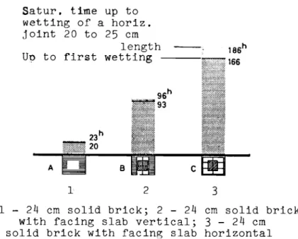
-18-Satur. time up to wetting of a horiz. joint 20 to 25 cm length Uo to first wetting 186 h ii}:i:)'::166 A 1 2 3
1 - 24 cm solid brick; 2 - 24 cm solid brick
with facing slab vertical; 3 - 24 cm
solid brick with facing slab horizontal
Fig. 8 hours. structure: 18.0 m/sec 0.8 litre/m2
90°
0.2 - 0.5 rnrn Saturation times in Factors affecting the wind velocityamount of rain
impingement angle of rain diameter of raindrops min SNOW CUXHAVEN ESSEN-MULHEIM I.'
I
wi ;; 116(1 h ii 0.) Fig.9
FElOOERG /lS 03 03I
Ii Annual hours of rainfall associated with windvelocities exceeding 17.5 m/sec. for the four main wind velocities
セiiNBZ •.10·(" &0'10 ReL. ,",uI'\'O'1''' F ... bLl\& 20 • 20 15 .10 II') S e E. '0 0 .Iij> <J \u <S • 10 0- ,.; セ
,
'J セ 20 0 0-rr '7 0 Fig. 10 iBGt[セNャoᄋHG • 1>0'. liE\... ,",ut'I'Q,1''j 1.5<-,., セtオ・」No FOil'" C.ONC.ll",.E,,:;,,5
Vented cast stone facing. No
condensate is formed within the wall section, as the cold side has low vapour resistance and
can let evaporation take place
svr : .,)o·c, jOio REI.... \10l"lm,T" 15 .,.., .10 :;l: (; £10 0 セ Jt, UJ セQP Of セ 5 ri セ & 'J 0 セzo (). II: ,. 0 Fig. 11 INT:+.zo·C,100'10 REI.... "0""'011''1 I.S c. .. !>1'OLC.()
Cast stone wall facing with fully
mortared and pointed joints. In this case
condensation occurs behind the closed facing, under the same boundary conditions as in Fig. 10
-20-fl.,.: MBGッGセL &0,,/. IIEL.. \.101<\\0\"1',/ IPIlT: +'-'0 0(" bo1o REI..., H<.II"\'O'1'"" 20 .20 15 .10 0"') セ E10- 0 f: I I NZM[G^クセ
-...セMMM Fig. 12hゥセィ thermal insulation on the cold
side of the wall and high resistance to diffusion on the warm side prevent condensation within the wall if
thermal insulation is adequate
E1T: -"'oOC , go 70 Rl'L. H"'<" 0''1"';-
'Ill'"
セ•
zeNセ I,"07.
IlE.... """\lI>\T'I 20 S,.ut.to-\5 f.10 f: .20 .10 o セ ·\0セ
r! -20 Fig. 13High thermal insulation on the warm side of the wall in conjunction with low resistance to diffusion of water vapour gives rise to condensation
HT:-.Jot, &0'7. ReL. エ||ャBBセiGMGQ '>ITセ ...olo'\:.,"0"/. Ra.. >\\l 1'\'0'1''/ ,sTU(.CO 20 .20 iMjNMMMMMMN[N[NセNiェイGMMM
5",.,
BLLᆬッセB 1'IlE!»\lQE o .10 セMQP 15 oJ' <II W t!5 III セ g a: > 0 Fig. 14High thermal insulation on the warm side calls for a vapour barrier to prevent
condensation within the wall
·C
セ
75 70 1'I\c:.,ole.5 ...\'>-- -':hR 59...<:.,. 65 Fo"'" <!.oOlt. 4h 60 55 -50 45 40 35 30 25...
20 Fif?;.15
セ...,.., foUl"
'.,M,mll,&", ..,pMMャMMMNNNNLLセL "1'1:"'1'."'EI'I!>. 9O'''T b ,,'.. 5;>00.... ---+----+-セo ...N\uャャエャャエtoMMMャイMMMセ⦅KMHeat levels (laboratory values) in a slab facing with 1 cm wide air cavity between the fixing mortar
-22-.,.! 80:70 -60 50 1---+-+--1' 40QMMMKMKMエMSセ 301---+-1---; Fiil;. 16
Increase in the thermal resistance
l/A (m2 h o C / k c a l ) in percent, エ。ォゥョセ
account of the ゥョウオャ。エゥョセ value of
a 1 cm wide air cavity behind the
ヲ。」ゥョセ panels
-15 -12 -lOoe
OUTDOOQ TEt'\9'.
fゥセN
17
1 = international surface
tempera-ture of external walls with minimum thermal insulation values according to DIN 4108 in the insulation ranges
I - III.
2 = increase in surface temperature
due to 1 cm wide air cavity behind facing panels
.
....
--- ---セMMM ---m I I OC19 18 17 16 15 0: 14 s: セ 13 w 12 d If11'"
セ QセRP -ts Fig. 18Internal surface temperatures of external walls with the minimum values of l/A in accordance with DIN
4108 (lines 1,
3, 5)
in relation tothe outside temperature. Increase
in surface temperature due to 1 cm wide air cavity behind facing panels