COMMERCIAL APPLICATION OF ALUMINUM
HONEYCOMB AND FOAM IN LOAD BEARING
TUBULAR STRUCTURES
byStefano Bartolucci
B.S. in Mechanical Engineering (cum laude), 2002 Universita' degli Studi di Modena, Modena, Italy
Submitted to the Department of Materials Science and Engineering in partial fulfillment of the requirements for the degree of
Master of Engineering in Materials Science and Engineering
at the
Massachusetts Institute of Technology
September 2004
Copyright © Stefano Bartolucci 2004. All rights reserved.
MASSACHUSETTS INSTITUTE
OF TECHNOLOGY
FEB 16 2005
LIBRARIES
The author hereby grants MIT permission to reproduce and to distribute publicly paper and electronic copies of this thesis document in whole or in part
Signature
of Author
...
...
.
e......
Department of Materials Science and Engineering . August ) 1, 2004
Certified by ... ..
Lorna J.Gibson Matoula S. Salapatas Professor of Materials Science and Engineering Thesis Supervisor
Certified
by
...
...-
...
jr Thomas W. Eagar Thomas Lord Professor of Materials Science and Engineering Thesis Coadvisor
Accepted
by ...
...
Carl. V. Thomson Stavros Salapatas Professor of Materials Science and Engineering Chairman, Departmental Committee on Graduate Students
COMMERCIAL APPLICATION OF ALUMINUM
HONEYCOMB AND FOAM IN LOAD BEARING
TUBULAR STRUCTURES
byStefano Bartolucci
Submitted to the Department of Materials Science and Engineering on August 11, 2004 in partial fulfillment of the requirements
for the degree of Master of Engineering in Materials Science and Engineering
Abstract
Small dimension engineering tubular structures subjected to a complex load system are designed like hollow circular shells. For minimum weight design, the ratio between the shell radius and the thickness has to be as large as possible, but its maximum value is limited by the onset of local buckling. Tubular natural structures subjected to a complex load system have often an outer shell of solid material supported by a low density, compliant core, which makes them more resistant to local buckling. Biomimicking of natural constructions offer the potential to improve the design of small diameter tubular engineering structures.
Here, the fabrication technology of biomimicked engineering tubular structures integrating aluminum foam or honeycomb as core material is discussed. A viability analysis is presented including technical performance, cost, utility, and risk assessments. Aluminum compliant core shells have potential for substituting CFRP and aluminum tubular structures in aerospace and high-level sport applications. The case of sailboat masts was considered in detail. Results of our analysis proved that use of honeycomb as core material can lead to a significant reduction of the mast weight. Business opportunities based on this application are discussed.
Thesis Advisor: Lorna J. Gibson
Acknowledgements
Life at M.I.T. has been a great personal and intellectual adventure, and my pleasure has mainly been due to the extraordinary people around me and their professional qualities.
Principal among these, I would like to thank my advisor, Prof. Lorna Gibson, for her guidance, patience and encouragement during the course of this thesis, especially when things did not turn out well. She has taught me much about perseverance and organization in my work.
I also would like to thank Prof. Thomas Eagar for his brilliant inputs regarding my thesis: every single talk we had was a unique and valuable experience for me.
It was a pleasure to interact with the M.I.T Welding Lab group. I wish to thank in particular Joel William for a wonderful lab experience and Kris Musso for his important advice.
I would like to thank those who have been instrumental in enabling me to endure the difficult times, as well as to enjoy the glad times, in particular Diego, Alfredo, Markus, Padraig, and Paolo.
Lucy, I wish to express my deepest gratitude for the constant support, understanding, and love that I received from you through all this period.
Finally, but most important, I wish to thank my family, whose moral and financial support enabled me to study here in M.I.T. Without you, this could have not been possible.
Table of Contents
page Title page 1 Abstract 2 Dedication 3 Acknowledgements 4 Table of Contents 5 List of Tables 9 List of Figures 10List of Notations and Symbols 15
Chapter 1: Introduction and Current Technology 20
1.1 Background and Significance 20
1.1.1 Engineering Tubular Structures 20
1.1.2 Natural Tubular Structures 21
1.1.3 Biomimicking of Natural Cylindrical Tubes 26
1.2 Current Technology: Aluminum Foam Manufacturing Methods 27
1.2.1 Production Methods Overview 27
1.2.2 CYMAT 28
1.2.3 ALPORAS 29
1.2.4 AL ULIGHT/FOAMINAL 31
1.2.5 DUOCEL 32
1.3 Current Technology: Aluminum Honeycomb Manufacturing 34
1.3.1 Generality 34
1.3.2 Expansion Process 34
1.3.3 Corrugation Process 35
1.4 Current Technology: Bond Technologies for Aluminum Foam 37 Sandwich Structures
1.4.1 Introduction to Aluminum Foam Sandwich Structures 37 1.4.2 Feasible Al-Foam Al-Sheet Joining Technologies 38
page
1.4.2.1 Mechanical Fastening Elements 38
1.4.2.2 Gluing 38
1.4.2.3 Welding 39
1.4.2.4 Soldering and Brazing 40
1.4.2.5 Transient Liquid Phase Bonding 41
1.4.2.6 Nickel Plating and Brazing 42
1.4.3 Shear Testing on Foam-Sheet Joints 43
1.4.4 Summary 45
1.5 Current Technology: Bond Technology for Aluminum Honeycomb 46 Sandwich Structures
1.5.1 Adhesive Bonding 46
1.5.2 Brazing 48
1.6 Fabrication of Tubular Structures with Compliant Core 49
1.7 References of Chapter 1 51
Chapter 2: Viability Assessment 54
2.1 Introduction 54
2.2 Technical Performance Assessment 57
2.2.1 Hollow Circular Shells 58
2.2.2 Stringers-Stiffed Isotropic Shells 61
2.2.3 Hollow Sandwich-Wall Circular Cylinder 66
2.2.4 Shells with Compliant Core 70
2.2.5 Comparison of Different Form of Constructions 74
2.2.6 Effect of Materials 76
2.3 Cost Estimation 80
2.4 Value in the Market 84
2.5 References of Chapter 2 90
Chapter 3: Sailboat Masts with Cellular Metal Core 92
page
3.2 Mast Load System 92
3.3 Mast Design: Functional Requirements 97
3.3.1 Stiffness 97
3.3.1.1 Global Buckling 97
3.3.1.2 Transverse Mast Stiffness E.Iyy 100
3.3.1.3 Longitudinal Mast Stiffness E-Ixx 101
3.3.2 Minimum Weight 102
3.3.3 Maximum Aerodynamics Efficiency 103
3.4 Mast Design: Materials Selection 106
3.4.1 Figures of Merit 106
3.4.2 Wood 107
3.4.3 Aluminum 107
3.4.4 Steel and GRP 107
3.4.5 CFRP 108
3.5 Application of Cellular Metals in Sail Masts: Circular Sections 109 3.5.1 Circular Cylindrical Aluminum Extruded Tube 111 3.5.2 Aluminum Circular Cylindrical Sandwich with Foam Core 113 3.5.3 Aluminum Circular Cylindrical Sandwich with Honeycomb 116
Core
3.5.4 Aluminum Circular Cylindrical Shell with Foam Core 118
3.5.5 Aluminum Circular Cylindrical Shell with Honeycomb Core 120
3.6 Application of Cellular Metals in Sail Masts: Elliptical Sections 122
3.6.1 Estimation of the Local Buckling Stress 122
3.6.2 Aluminum Elliptical Cylindrical Extruded Tube 124 3.6.3 Aluminum Elliptical Cylindrical Sandwich with Foam Core 126 3.6. 4 Aluminum Elliptical Cylindrical Sandwich with Honeycomb 128
Core
3.6.5 Aluminum Elliptical Cylindrical Shell with Foam Core 129
3.6.6 Aluminum Elliptical Cylindrical Shell with Honeycomb Core 131 3.7 Application of Cellular Metals in Sail Masts: Discussion 133
page
3.8 References of Chapter 3 137
Chapter 4: Investment Assessment for Sailboat Masts with Cellular
Core 138
4.1 Introduction 138
4.2 Market Assessment 140
4.2.1 Generality 140
4.2.2 Mast Market 141
4.2.3 ,Sailboat Market Projections 142
4.2.4 .End Users 144
4.2.5 Overall Marketing Strategy 144
4.2.6 Competition 145
4.2.7 Potential Revenue Flows 147
4.3 Value Capture 148
4.3.1 Generality 148
4.3.2 IP Asset and Defense 149
4.3.3 ndustry Structure 149
4.3.4 Organizational Structure 150
4.3.5 ,Probability of Value Capture Summary 151
4.4 Investment Decision 151
4.5 References of Chapter 4 153
List of Tables
page
Table 1.1: Applied sheet and foam materials. 43
Table 1.2: Investigated joining technologies. 43
Table 1.3: Influence of the joining technology on the theoretical maximum 44 tensile shear stress in quasi-static loading.
Table 1.4: Evaluation of the investigated joining technologies. 45 Table 2.1: Experimental values of the panel efficiency coefficient. 65 Table 2.2: Materials for lightweight compression commercial hollow tubes. 76 Table 2.3: Different constructions for lightweight compression structures. 79
Table 2.4: Sandwich structures under investigation. 80
Table 2.5: Cost of materials. 81
Table 2.6: Resources consumed in making composite honeycomb/foam core 82 shell.
Table 2.7: Utility of weight saving in transport systems. 85
Table 3.1: Calculation of the staying factor. 101
Table 3.2: Resistance to environmental conditions for materials employed in 106 masts.
Table 4.1: Mast markets (2000). 141
Table 4.2: Sailboat retail value in the United States (2000). 143
Table 4.3: U.S. sailboat masts producers. 146
Table 4.4: Management efficiency. 150
List of Figures
page
Figure 1.1: North American porcupine quill cross section. 22
Figure 1.2: North American porcupine quill cross section: detail. 22 Figure 1.3: Old World porcupine quill cross section: detail. 23
Figure 1.4: Grass stem cross section. 23
Figure 1.5: Grass stem cross section: detail. 24
Figure 1.6: Hedgehog spine longitudinal section. 24
Figure 1.7: Hedgehog spine longitudinal section: detail. 25
Figure 1.8: Biomimicking natural tubular structure. 26
Figure 1.9: A taxonomy of metal foam manufacturing process 27 Figure 1.10: Schematic illustration of the CYMAT process. 28
Figure 1.11: Foam produced by the CYMAT process. 29
Figure 1.12: Schematic illustration of the ALPORAS process. 30
Figure 1.13: Foam produced by the ALPORAS process. 30
Figure 1.14: Schematic illustration of the powder compact process. 31
Figure 1.15: Foam produced by the powder compact process. 32
Figure 1.16: DuocellTM foam produced by investment casting. 33
Figure 1.17: Expansion manufacturing process. 34
Figure 1.18: Corrugation manufacturing process. 35
Figure 1.19: Principal honeycomb cell configurations. 36
Figure 1.20: Geometry of the samples for the shear test. 44
Figure 1.21: Flat sandwich panel produced by heated press. 46 Figure 1.22: Curve sandwich panel produced by vacuum bagging or 47
autoclave.
Figure 1.23: Vacuum bag system: a flexible bag is sealed over the sandwich 47 and the vacuum is created.
Figure 1.24: Schematic of the autoclave. 48
page Figure 1.26: Comparison between foam-filled shell produced by the (a) 50
Fraunhofer process and (b) the co-forming process.
Figure 1.27: Insert for honeycomb core shell. 50
Figure 2.1: The investment methodology for materials (IMM). 55 Figure 2.2: Market size and value capture as measures of attractiveness of a 56
material innovation.
Figure 2.3: Schematics of cross-sections of cylindrical tubes. (a) Empty shell 57 (b) longitudinal hat-stiffed shell (c) sandwich wall shell (d) shell with
a complaint honeycomb or foam core.
Figure 2.4: Maximum stress for given structural index. 60
Figure 2.5: Stiffeners considered in this study. 62
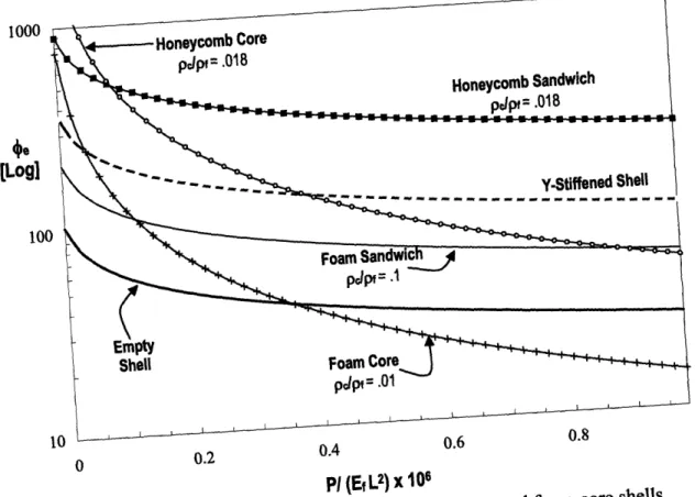
Figure 2.6: Thin walled cylindrical shell with a compliant elastic core. 70 Figure 2.7: Normalized weight index plotted against normalized load index, 74
showing curves for empty shell; longitudinal Y-stiffened shell; foam sandwich shell; honeycomb sandwich shell; shell with foam core; shell with honeycomb core; y 0.5, ey = 0.007, v = 1/ 3; (R/t < 50.)
Figure 2.8: Normalized weight index plotted vs. load index y 0.3, 75 (50 < R/t < 200)
Figure 2.9: Normalized weight index plotted vs. load index y 0.2, 75
(R/t > 200)
Figure 2.10: Material selection chart for commercial hollow tubes, plotted on 77 the density-modulus chart.
Figure 2.11: Shape factors for hollow, honeycomb- and foam-core shells. 78 Figure 2.12: Unit cost plotted against production volume for honeycomb 83
sandwich shell.
Figure 2.13: Unit cost plotted against production volume for foam sandwich 83 shell.
Figure 2.14: Performance-cost tradeoff for structural compression 85 lightweight tubes.
page Figure 2.15: Types of Performance/Cost Substitution for cellular metal 86
shells.
Figure 2.16: Value chain in material innovation. 87
Figure 2.17: Market applications for maturity of application and system 88 complexity.
Figure 3.1: Forces on a sailing yacht. 93
Figure 3.2: Sail loads on rigging. 94
Figure 3.3: Mast load system. 95
Figure 3.4: Mast compressive load calculation. 96
Figure 3.5: Types of rig considered in the study. 98
Figure 3.6: Types of staying. 99
Figure 3.7: Reference system. 99
Figure 3.8: Panel notation for the different types of rigs. 100
Figure 3.9: Pressure distribution along a sail. 103
Figure 3.10: Flow around a mast/sail combination. 104
Figure 3.11: Wing-mast concept; creating a mast from an existing airfoil. 104 Figure 3.12: Profiles of masts of different dimension (measured in % of the 105
total chord).
Figure 3.13: YD-40 rig. 110
Figure 3.14: Circular cylindrical hollow section. 111
Figure 3.15: Weight per unit length plotted against the radius for hollow 113 circular shell.
Figure 3.16: Circular sandwich shell section with foam core. 113 Figure 3.17: Weight per unit length plotted against the radius for foam core 115
sandwich shells with different relative densities.
Figure 3.18: Circular sandwich shell section with honeycomb core. 116 Figure 3.19: Weight per unit length plotted against the radius for 117
honeycomb-core sandwich shells with different relative densities.
page Figure 3.21: Weight per unit length plotted against the radius for foam core 119
shells with different relative densities.
Figure 3.22: Circular cylindrical hollow section with honeycomb core. 120 Figure 3.23: Weight per unit length plotted against the radius for honeycomb 121
core shells with different relative densities.
Figure 3.24: Geometry of elliptical cylindrical shell. 122
Figure 3.25: Elliptical cylindrical hollow section. 124
Figure 3.26: Weight per unit length plotted against the equivalent radius for 125 elliptical cylindrical hollow shell.
Figure 3.27: Elliptical sandwich shell section with honeycomb core. 126 Figure 3.28: Weight per unit length plotted against the radius for elliptical 127
foam- core sandwich shells with different relative densities.
Figure 3.29: Elliptical sandwich shell section with honeycomb core. 128 Figure 3.30: Weight per unit length plotted against the radius for elliptical 129
honeycomb-core sandwich shells with different relative densities.
Figure 3.31: Elliptical cylindrical hollow section with foam core. 129 Figure 3.32: Weight per unit length plotted against the radius for elliptical 130
foam-core shells with different relative densities.
Figure 3.33: Elliptical cylindrical hollow section with honeycomb core. 131 Figure 3.34: Weight per unit length plotted against the radius for elliptical 132
honeycomb-core shells with different relative densities.
Figure 3.35: Weight per unit length plotted against the radius for hollow 134 circular shell, foam-core sandwich shell, foam reinforced hollow
shell, honeycomb-core sandwich shell, honeycomb reinforced hollow shell.
Figure 3.36: Weight per unit length plotted against the radius for hollow 135 elliptical shell, foam-core sandwich shell, foam reinforced hollow
shell, honeycomb-core sandwich shell, honeycomb reinforced hollow shell.
page
Figure 4.2: Market assessment. 140
Figure 4.3: Sailboat sells in the United States by category. 142 Figure 4.4: Market penetration of CFRP in boats' hulls. 147
Figure 4.5: Value capture assessment. 148
Figure 4.6: Value created by the technology under investigation. 151
Figure 5.1: The carbon fiber mast of the trimaran Sergio Tacchini, produced 155 by Espace Composite (Lunel, France).
List of Notations and Symbols
A = area of the cross section;
Ast = stiffener area;
B 0.58 = Allen coefficient; Cmi = cost of the material i; C, = cost of tooling;
CL = overhead rate; Ce = cost of energy;
Cs= cost of space;
Cip= royalty payments, cost of intellectual properties;
CLO = basic overhead rate; Cc = cost of capital; b = radius of bore hole;
c = cell size;
d= core thickness;
E = Young's modulus of core; Ef Young's modulus of shell;
F = compressive force acting on the mast;
Fcit = maximum compressive force acting on the mast; f = total material utilization fraction;
I = moment of inertia of the cross section; i= stiffeners interspacing; K = buckling coefficient; =1--
1,
-v
22 2
4Pc ?2
-J = torsional moment of inertia;
I = length of column;
leq = equivalent length of column; L = length of shell;
Lf = load factor;
N = P(2,rR);
N = ellipse major semiaxis; h = production rate; n = production volume;
n, = nyy(p) = half-wavelength in buckled shape; 2
(E, )
M=B
M= ellipse major semiaxis;
Ml = (E = performance index;
P
mi= mass of the material i;
P = axial compressive load; p = panel number;
R = radius to mid-plane of thickness;
I]- Y 2) } 3 /2
= radius of curvature of surface;
M2 RN =
NN
R, = (N M1 = equivalent radius; s = circumferential coordinate;
sf= traverse stability factor;
T= transverse force applied in the masthead;
t = thickness of shell;
t = (Ast /i)+ t' = effective face thickness;
t = tooling life (units); t, = capital write-off time;
U= utility coefficient; W= shell weight;
(a
-
Kr
t)2_ng
,8 = shroud angle; = safety factor; R= 1 Rs N 2 1 +I = half beam; cy Ey = E-;
Ef
q = PC = relative density; PsK = knockdown factor shell parameter;
= A = flexural shape factor;
4zK
=i = torsional shape factor;
y = knockdown factor;
A=
1+5. c ;icr = critical buckling wavelength parameter;
5 = section radius of gyration;
qf z /(25) = radius of gyration of an unstiffened panel of thickness t; V = Poisson's ratio of core;
V = Vf = Poisson's ratio of shell; Pc = density of core;
Ps = density of parent material; p = pf = density of shell;
2
y = righting moment lever arm;
E=
1
+5. P (cr ]a
=
N/t;
a, = global buckling axial stress;
a2 = local buckling axial stress;
ry = yielding axial stress;
Uwr = wrinkling stress;
adm = face dimpling stress;
1
= eti(v2t[3/N 5 = MIN= ellipticity;
Chapter 1
Introduction and Current Technology
"When Nature builds large load-bearing structures, She generally uses cellular materials: wood, bone, coral.
There must be good reasons for it"
M. F. Ashby 1.1 Background and Significance
1.1.1 Engineering Tubular Structures
Cylindrical shells are used in a variety of applications [1]: examples include tubular trusses, silos, tanks, submarines, aircraft fuselages, rockets, and legs of offshore platforms [1]. These components are generally subjected to a complex system of loads: compression, torsion, and bending. For a given material, the resistance to a particular mode of load depends on the shape of the component. To consider this, Ashby [2] has introduced a cross-sectional shape factor for each mode of loading. Defining I as the second moment of inertia and A is the cross area of the section, for axial compression and bending, the shape factor is [2]:
O-
A2; (1.1)In the same way, for torsion, defining J the torsional moment of inertia:
4zJ
= A2; (1.2)
The shape factor measures the efficiency of a cross-sectional shape to resist buckling, bending, and torsion. For a hollow circular shell, the shape factor is simply given by the ratio between the shell radius, R, and the wall thickness, t. Therefore, tubular sections become more efficient as the ratio between the shell radius and wall thickness increases. The shape factor can be augmented, enhancing the efficiency of tubular sections, up to a limit determined by the onset of local buckling or by manufacturing constraints.
Maximum shape factors for commercial aluminum and steel circular hollow tubes, which are designed against local buckling, are respectively 25 and 30 [2]. On the other side,
wood hollow tubes, due to the anisotropy of the material and machining difficulties, have a maximum shape factor of four [2]. When local buckling is the limiting factor, bracing can suppress it. Shells stiffened by longitudinal stringers and stabilized at intervals by lateral stiffeners, such as ribs or formers, are common in engineering applications, such as aircraft fuselages or legs of offshore structures. For these structures, values of the shape factor of the order of 102 or 103 are common [1]. However, if the diameter of the shell decreases, the stiffeners have to become thinner and deeper [1]: this sets a lower limit to the radius of stiffened shells, which cannot be less than one meter.
1.1.2 Natural Tubular Structures
Solid sections and hollow tubes of the types used in engineering applications are widespread in nature, for example in tree trunks. Karam in his Ph.D. dissertation described different types of tubular structures, which can be found in nature [1]: he showed that animal quills, plant stems, and spines present a dense outer shell with a more compliant cellular core. He distinguished four different microstructures. The first structure, which can be found for instance in the North American porcupine quills, is a shell completely filled with foam-like material (see Figure 1.1). Figure 1.2 shows the cellular structure more in detail. The second type of structure, which can be observed for instance in the Old World porcupine, is a shell filled with foam but with an additional thin, longitudinal stiffener running radially from the outer shell of the quill toward the center (see Figure 1.3). Another variant of the first type is a shell filled with foam but with a central hole; this microstructure can be found in most plant stems (see Figure 1.4). Figure 1.5 shows the microstructure of the core in detail. The fourth microstructure, which can be: observed in the spines of the hedgehog (Figure 1.6), presents closely spaced
longitudinal and radial stiffeners and resemble a square-cell honeycomb (Figure 1.7). Gibson [3] observed that sandwich structures with a foam or honeycomb core are also diffuse in Nature, as in the human skull or in the tall leaves of the marshy plants such as cattails and iris.
Figure 1.1: North American porcupine quill cross section [4]
Figure 1.3: Old World porcupine quill cross section: detail [1]
Figure 1.5: Grass stem cross section: detail [4].
.
Figure 1.7: Hedgehog spine longitudinal section: detail [4].
In the early 16t h century, Leonardo da Vinci was writing: "Observe the Nature and learn
from Her.. No action of the Nature can be made in a more efficient way with the same resources. (Code Arundel)". Natural structures are the result of years of evolution and, consequently, are often optimized. Analyses of the mechanical behavior of the compliant core natural shells ([1]- [5]) showed that in all cases, the structures are loaded by some combination of bending and axial load and that the compliant core, acting as an elastic foundation, increases the resistance to local buckling. As result, for a given buckling resistance, the weight of the structure, and therefore the total biomass, is reduced respect to a hollow shell [1]. It is remarkable that the shells represented in Figures 1.1-1.7 have
an outer radius, R, 0.5 < R 1 mm, and wall thickness, t, t 40 im > 15 < R/t < 25 [1].
These natural cylindrical shells are therefore small on the absolute scale, but characterized by relatively large values of R/t.
1.1.3 Biomimicking of Natural Cylindrical Tubes
In the previous section, we have seen that some natural cylindrical tubular structures,
subjected to combined axial and bending load, present a light, compliant core with a microstructure that resembles that of honeycomb or foam. We have also seen that these natural shells are small in dimension but characterized by relatively large values of the
shape factor. Conversely, engineering tubular structures with large shape factors using stringers and ribs are characterized by large diameters. Biomimicking of natural constructions can therefore offer the possibility for the design of small diameter tubular engineering structures that are more efficient and lighter than ones existing today [4]. Natural constructions can be replicated using a foam or honeycomb core joined to a solid
outer layer (see Figure 1.8).
Figure 1.8: Biomimicking natural tubular structure [4]-[6].
The objective of this thesis is to analyze the performance, the manufacturability, and viability of load-bearing tubular structures employing cellular metals, in view of their commercialization. Chapter 1 reviews the current methods to manufacture cellular metals and conventional joining techniques, which are feasible for compound structures integrating aluminum foam and honeycomb. Chapter 2 examines the viability of metal compliant core shells in terms of their technical attributes, cost, and risk of investment. In Chapter 3, we compare the design of a sailboat mast incorporating cellular metals to current mast designs. Chapter 4 describes the business plan of a company producing cellular metal sailboat masts. In Chapter 5, the conclusions of this work are summarized.
1.2 Current Technology: Aluminum Foam Manufacturing Methods
1.2.1 Production Methods Overview
In this section, we describe the manufacturing methods to produce cellular aluminum foams. Metal foams were for the first time obtained by B. Sosnik in 1948 [7]: the method he used was based on adding a volatile phase, e.g. mercury, to the metal to be foamed, e.g. aluminum, inside a pressure vessel, melting the metal and suddenly reducing the pressure to allow foaming [7]. Metal foams produced in this way were expensive, irregular and, more important, contained traces of toxic metals. After then, many advances have been made and today several techniques are known for producing metal foam [8] (see Figure 1.9). Although the foaming always takes place in the liquid phase, Ashby et al. distinguished four major manufacturing routes, each corresponding to different initial states of the metal to be foamed: liquid metal, powder metal, metal vapor and metal ion solution [9]; of these, only the first two find commercial application and are represented in Figure 1.9.
Production methods ,,,,,,,, .. . Melt route I . .. ... .
IiSril
strwutures I techniques I ' .. I Self-foming 5truturt"; timiiin- with -rt I iiiii i ii i Powder moute .. .. ... ... ...]
sui:Sf-foTrming ; rstncturn;ictl.ren :. ~ . , <tll- l-tIH/- v igj
-q5PC
ISxklunntic
..I
CYNI-f MTlulkn TDC tLi' IWDLW .: i WR | I\DRO sphre C z. Toe J(AMINAL
Figure 1.9: A taxonomy of metal foam manufacturing proc es [10]. Figure 1.9: A taxonomy of metal foam manufacturing processes [10].
cJ.i-rumtag e"l- mna
nzi,J mule 4 . t.o refined .rcb~edj I::ctMp.,s I fVrap.;I a.etis i . .. i I I I
A second level of classification is the strategy to generate porosity (see Figure 1.9): self-formation or pre-design [10]. The former includes all the methods in which the porosity is obtained through the nucleation and subsequent growth of gas bubbles; foams produced in this way have a stochastic structure [11]. In the latter, the resulting structure is determined by a cell-forming mold [10]. The third level of classification is the gas source used to create porosity: foaming can be obtained injecting a gas or by the decomposition of gas releasing particles [12]. All the techniques represented in Figure 1.9 are suitable for aluminum, but only four have reached the commercial state. They have taken a commercial name, given by the manufacturer, i.e. CYMAT, ALPORAS, DUOCEL, and ALULIGHT/FOAMINAL. In the following, these production methods are discussed in more detail.
1.2.2 CYMAT
In the CYMAT process, aluminum foam is produced injecting gas in the melt metal [13] (see Figure 1.10). One of the problems of this approach is that normally the gas bubbles injected in the melt would tend naturally to rise to the surface and to escape [14]. The gaseous bubbles can be retained increasing the viscosity of the metal. In the CYMAT approach [13], a dispersion of finely grinded particles of a refractory, generally silicon carbide is added to the melt. Good viscosities are obtained adding 5-15% by volume fraction of SiC particles smaller than 20 jum [13]. Gas is then added to the melt using a rotating impeller (see Figure 1.10) and a liquid foam forms at the surface.
The foam liquid is then cooled below the liquidus temperature of the melt and solidified. There are several options for this step. In the method represented in Figure 1.10, the foam is drawn off the liquid surface with a conveyor belt. The most successful variant consists of pulling off the foam from the surface of the molten metal vertically using a pair of moving belts [15]: this has the advantage to reduce the effect of the gravity during the drainage of the foam [14]. Other methods can be found in literature [16-18]. Advantages of the CYMAT process are represented by the low cost and simplicity of production, low cost starting material (recycled MMC scrap), economy of scale and good density control [8]. The main disadvantage of this method is that only a relatively small number of large bubbles is generated, which leads to rather coarse and irregular shaped pore distribution [10] (see Figure 1.11). In the next section, we describe a technique in which a large number of gaseous bubbles are created by the thermal decomposition of solid ingredient.
Figure 1.11: Foam produced by the CYMAT process [19] 1.2.3 ALPORAS
Shinko Wire Company, Ltd. Japan attempted another approach to foam metal melts [20]. Rather than inject gas into the molten metal, a blowing agent is added, typically titanium hydride (TiH2) [20]. The blowing agent is stable at room temperature, but when heated
up, it decomposes, releasing gas which propels the foaming process (see Figure 1.12) [21].
The advantage of using a solid foaming agent is that it is possible to disperse the gas
more unifornmly throughout the melt [22]. The result is that the microstructure of this foam, which is commercialized with the trade name of ALPORAS, is very homogeneous (see Figure 1.13). One disadvantage of the technique is that the viscosity of the melt still
needs to be adjusted and this is usually done by adding 1.5% by volume of Calcium [22], which is toxic. Another limit comes from the absence of economies of scale, which is inherent in the batch nature of the process. For this reason, ALPORAS foams are among the most expensive in the marketplace.
1.5%Ca 1.6%Ti 2 Pure Al I I
IiI
*# / anQf You %. 680oCThickening Foaming Cooling Foamed Slicing Block
Figure 1.12: Schematic illustration of the ALPORAS process [22].
r S po-cs 14
1s
o
poc tep
s
1.2.4 AL ULIGHT/FOAMINAL
In this section, we discuss the powder-metallurgical route to produce metal foams following the process invented and patented at the Fraunhofer-Institute, Germany by Baumeister [23-24]. A schematic diagram of the process is shown in Figure 1.14.
Figure 1.14: Schematic illustration of the powder compact process [24].
The most important feature of this method is that both the metal to be foamed and the foaming agent, typically titanium hydride, are introduced in the solid state as powders. The production process begins mixing the two types of powders [25]. This mix is then compacted to yield a dense semi-finished product called "foamable precursor material" [26]. In Figure 1.14, the compaction of the powder is done by axial compression, but also other methods as extrusion or powder rolling can be used [25]. At this point, the precursor can be formed or machined in the desired size and shape (number 20 in Figure 1.14) [8]. In the last step, the precursor is heated up. At 465 C, the TiH2melts and the
i . ...
1..iI
16 I 4 4 7I1released gas forces the material to expand creating the foam [25]. Figure 1.15 shows a typical cross section of foam obtained through the Fraunhofer process. Advantages of this technique are represented by the simplicity of the process, the extensive range of shapes and densities, which can be obtained, and the possibility to create aluminum sandwich structures (AFS) in one-step process. Disadvantages incluse the cost of the powders, size limitations, difficulties in controlling the pore size and the mechanical properties of the final component. The most commercialized foam produced with the Fraunhofer process is produced by ALULIGHT International GmbH with the trade name ALULIGHT.
Figure 1.15: Foam produced by the powder compact process [8].
1.2.5 DUOCEL
DUOCEL, produced by ERG Materials and Aerospace, Oakland, California, is the only pre-designed foam with commercial applications. Although the manufacturing method of this foam is a trade secret and no patent has ever been filed, it is generally believed [14] that DUOCEL is obtained by investment casting from a "dummy" polymer foam. A schematic description of the process is given by Ashby [9] and Banhart [9]. In first place, a polymer foam mould is selected and filled with a slurry of heat resistant material [9],
e.g. plaster [8]. After curing the polymer foam is then removed and a melt metal is cast into the cavity which replicate the original polymer foam structure [8]. After solidification the mould material is removed by pressurized water and metallic open-cell foam, replicating the original polymer foam, remains [8]. Advantages of this method are
given by the high grade of regularity and reliability of the foam (see Figure 1.16), the possibility to obtain porosities as high as 98% and complex shapes. Main disadvantages are represented by the complexity of the process, the cost of the foam and obvious difficulties to scale up the process.
1.3 Current Technology: Aluminum Honeycomb Manufacturing
1.3.1 Generality
There are five methods to manufacture metal honeycomb, based on the way in which the nodes are attached [27]. These methods are resistance adhesive bonding, welding, brazing, diffusion bonding, and thermal diffusion [27]. Probably more than 95% of honeycombs are produced through adhesive bonding [27]. The limitation of adhesive bonded honeycomb is represented by the maximum temperature that it can withstand, usually 399 °C with polyimide or 204 °C with nylon epoxy and nitrile phenolic adhesives [27]. When higher operational temperatures or severe environmental conditions are required, cores can be manufactured using resistance welding, brazing, or diffusion bonding, even though these processes are more expensive than adhesive bonding [27].
There are two basic techniques to convert a sheet of metal into honeycomb: the expansion process and the corrugation process.
1.3.2 Expansion process
BE
Expanded Panel
Figure 1.17: Expansion manufacturing process [27]
The majority of the adhesive bonded cores are made by the expansion process shown in Figure 1.17. At first, a corrosion resistant coating is applied to the foil sheets and
adhesive lines are printed. After the sheets are cut and stacked one upon the other. The HOBE is brought to the autoclave, where the adhesive is cured under high temperature and pressure. Then the HOBE is cut into slices of the required thickness and expanded: when the metallic cores are expanded, the sheets yield plastically at the node-free wall joints and thereby retain their expanded geometric shape [27].
The method described is working for metallic honeycomb; for non-metallic honeycomb, like the NomexTM , the process is a little different. Here is enough to say that the honeycomb after the expansion has to be held in a rack. Then the honeycomb block is
dipped in liquid resin and oven cured [27].
1.3.3 Corrugation process
nl,,r,,,l ,nt--rkat .nrr nattd Rnk
Roll Corrugating Rolls
Figure 1.18: Corrugation manufacturing process [27].
The corrugation method, invented by Hexcel, was the first used to produce aluminum honeycomb. This system is still used today to produce high-density metallic cores, even though is expensive [27].
The method is shown in Figure 1.18. In the process, the sheets are first corrugated and adhesive is placed at the nodes (now this is done automatically). Then the sheet are piled up and cured in the oven. As the sheets cannot be compressed much during the curing, a thick layer of adhesive is required. Generally the quantity of adhesive needed in the corrugation process can be ten times that needed in the expansion manufacturing process.
Brazing, diffusion bonding or spot-welding are just different variants of the corrugation process, in which the nodes are welded instead to being adhesively bonded. Corrugated aluminum honeycomb is made because above 12 pcf it becomes impossible to expand the HOBE. In Figure 1.19 are represented the most common cell configurations manufactured [27].
Figure 1.19: Principal honeycomb cell configurations (elaborated from [28])
HEXAGONAL HEXAGONAL REINFORCED
I I
I
DOUBBLE FLEX® OVEREXPANDED OX ... OVEREXPANDED OX® i-1.4 Current Technology: Bond Technologies for Aluminum Foam Sandwich Structures
1.4.1 Introduction to Aluminum foam sandwich structures
For structural applications metal foam has to be used in combination with conventional dense metal structures, such as sheets, tubes or more complex-shaped hollow structures: this allows for optimized mechanical properties in a given situation.
Aluminum foam sandwich (AFS) panels can be produced very elegantly by roll-cladding face sheets to a sheet of foamable precursor material, then creating the desiderated shape in an optional working step, and finally foaming the entire composite [29] (Fraunhofer process). Foaming will create a highly porous core structure without melting the face sheets if the melting points of the foam and the face sheets are different and the process parameters are chosen appropriately.
One consequence of the production process for aluminum foam sandwich panels (AFS) as described is that the performance of the sandwich is not as good as its components will allow [30]. For the precursor to foam, the sandwich panel must be heated close to the melting point of the precursor alloy. To keep the facings intact, the melting point of the foam alloy must be kept low. This is generally achieved by using an alloy with high (7 - 12%) Si content. These alloys have mechanical properties that are considerably less than typical aluminum alloys. In addition, the alloy used for the facings cannot be dependent on heat treatment for its properties, due to the high foaming temperature. Another limitation is represented by substantial cost of the powders. As a result, aluminum foam sandwich panels produced through the Fraunhofer process present modest mechanical properties and utility compared to the panels produced by joining facings and core after foaming. In this report an overview of feasible conventional joining technologies between metal foams and sheets is presented.
1.4.2 Feasible Al-foam Al-sheet Joining Technologies 1.4.2.1. Mechanical fastening elements
Foams have a cellular structure resembling, in some ways, that of wood. Because of this, foam sandwich panels can be developed in ways similar to wood sandwich panels: in particular using mechanical fastening elements [9]. There are many mechanical fastening elements available, ranging from hollow spheres- to metal-plugs, as well as nails, screws and rivets, even though experiments show that there are only a few suitable technologies in which the strength of the joint is approximately the strength of the applied cellular material [31]. In general, fasteners using not only a frictional-, but a form-fitting mechanism as well are preferred: for this reason screws and blind rivets are preferred to nails [31]. Other solutions, like the integration of screw sockets into the foam structure have proved to be not viable, especially in light of cost considerations [32]. Mechanical fastening elements although cost attractive, are strongly limited by the non-uniform distribution of the stress inside the structure and the additional space required [32].
1.4.2.2 Gluing
Adhesive bonding is the most obvious and straightforward technology that can be used to produce AFS structures [33]. Epoxy-based systems curing at 180 °C for 30 minutes are available as conventional glues or as expanding glues, which are very convenient for bridging high tolerances and for integrating foam bodies into hollow extruded profiles [31]. The joining is caused by adhesive forces between the surface of the substrate and the glue: consequently, well-glued sample should not fail at the interface, as the adhesive forces caused by ionic bonding or polar interactions should be higher than the cohesive forces in the glue or the substrate [33]. When the foam does not present casting skin, joining is still possible, even though a greater consumption of adhesive is to be expected (weight increase, cost) because of the significantly enlarged surface area [31]. Other drawbacks of the technique are low thermal stability, mismatch of expansion coefficient and the possible creation of thermal and electrical isolation barrier [9].
1.4.2.3 Welding
Welding processes that have been shown suitable for joining aluminum foams are laser-beam welding [34] and ultrasonic welding [35].
In laser-beam welding the sheet material and the underlying foam structure are melted by the heat input of the laser and the metallic connection is created when the material re-solidifies [34]. Advantages of this technique are represented by the high welding speed, the keyhole effect and the locally limited energy input [36]. This feature in particular makes laser welding particularly attractive to join cellular metal, because unlike other systems, e.g. TIG, large collapse of the cellular structure is avoided. However early experiments at the Laser Zentrum in Hannover [37] showed that in applying laser welding to cellular metals special care is needed: in fact, the molten material can flow into the foam cells, filling them partially and a seam groove can form. Solutions to this
problem using different types of filler materials and modifying the process parameters are know [34], but control of the technique is still complex [31].
In the ultrasonic welding system an ultrasonic generator, a converter and a booster convert the main voltage into high frequency mechanical oscillation [35]. The actual bonding of the joining partners takes place through the transfer of this high frequency shear oscillation via the connecting surface of the welding tool into the sheet material [35]. At the same time a static pressure, perpendicular to the oscillation direction, is brought up [35]. A characteristic of the ultrasonic welding process is that it is a joining process in the solid state based on friction and consequently not a real welding process, where both joining partners are transferred into the liquid state for joining [31]. In comparison to other joining techniques, ultrasonic spot welding is characterized by low energy input, short welding times, < 3 s, as well as relatively low welding temperatures, < 300 °C and by allowing the joining without causing significant damage or deformation in the joining partners [38]. To realize ultrasonic roll seam welding of sheet material with Al-Foams it is necessary to insert more energy in the bonding zone [38]. As a consequence higher temperatures, up to 650 °C, melting of the aluminum joining partners and local deformations occur in the bonding zone [38]. Thus to realize roll seam welding appears to be more difficult than spot welding [38].
1.4.2.4 Soldering and Brazing
Soldering and brazing of aluminum foams is impeded by their oxide layer, which has to be removed before and during the soldering process [31]. The oxide layer can be removed in two ways: one is mechanical destruction by scratching, brushing, or ultrasonic vibration; the other is the application of a flux [31]. The latter causes serious corrosion problems if it is not removed properly [31]. In consequence, the joint requires good accessibility so that the flux can be washed out after the soldering process. This makes soldering with flux unsuitable for sheet-foam composites [31], where a connection along the whole surface is desired. When removing the oxide layer mechanically, the use of foam with a casting skin is advantageous, as the oxide layer is easier to remove [31].
Soldering
The S-bond TM is special alloy, developed by Euromat, to solder light alloys, that can be implemented in air, without fluxing agents and at relative low temperatures (far from the melting point of the joining partners) [39]. The S-bond TM alloy can be divided in two
categories: the Sn-based solders with a melting point from 208 to 238 C and the Zn-based solders with a melting point from 380-426 C. Other alloy components are Titanium, in which finely distributed inter-metallic phases lead to a strength increase; Silver and/or Copper, which are present to reduce the surface tension of the liquid solder; Gallium, which enhances the wetting of the metallic base solder. The S-bond process consists of different phases. In the first step, the solder alloy is deposited on the bonding surfaces of both the partners and the temperature is raised to the soldering point. Secondly, the two soldering surfaces are brought together and through relative movement of the two parts, the oxide film present between the melt solder and the metal is broken. The oxides on the substrate material are also partially broken during the process, so that a metallurgical interaction can take place. As relative movement between parts is necessary during soldering with a flux-free soldering, both surfaces have to be as plane as possible, so that the wetting of the substrate can take place everywhere. Alternatively, the oxide film could be broken with ultrasonic waves with a frequency of 60 kHz and amplitude of 2um. The latter system could be particularly effective in a fully automatic production line. If there is not a casting skin, the solder flows into the pores, but in contrast to glued
samples does not form a material-fitting joint with cell walls, as the oxide layer of the molten solder in the pores can not be torn properly during the relative movement of the parts. Consequently, the remaining joining area would be limited to the number of the present cell edges, which would result in a reduced strength of the structure. The technique is already well established for graphite-foam Al-sheet joining. Although flux-free soldering technology can be transferred to aluminum foams, corrosion preventing measures have to be taken as the Sn- and Zn-based alloys can cause corrosion problems in combination with aluminum.
Brazing
Brazing (T>450C) is a feasible joining process for aluminum foams [40]. Although non-corrosive fluxes are available for brazing, it advisable to coat the structure to protect it from humidity. The brazes are preferably Al-based and the furnace atmosphere should be inert. An alternative is the use of a porous filler material, which expands during the brazing process. This prevents a sudden change in porosity from foam to bulk. The working temperature of the filler material has to be low enough that the porous base material does not deform during the expansion of the filler material. Although this process has not been treated deeply in the literature, it is known that aerospace companies have incorporated aluminum foam into sandwich panels by using it. A current project at the University of Erlagen, is investigating the fundamentals of brazing techniques, first for flat and later for formed compounds with emphasis to the selection of suitable brazing materials and joining partners under consideration of different process parameters as, for example, temperature, hold time and surface preparation.
1.4.2.5 Transient Liquid Phase (TLP) bonding
In the transient liquid bonding (TLP) the Al-foam and the Al-sheet are joined together by sandwiching a thin layer of melting point depressant between them (in general a Cu-based alloy) and heating [41]. If the right interlayer material and conditions are chosen, we can heat the assembly to a temperature at which the bulk remains solid and where a region exists near the interface which is initially liquid but subsequently undergoes isothermal solidification. TLP bonding has a number of advantages over other joining
processes, combining positive aspects of both liquid and solid state techniques. For example, the presence of a liquid phase (in which solute can diffuse much more quickly than in solid material) means that joints can be produced without the imposition of any external pressure, as capillary forces will naturally cause the liquid to flow and eliminate interfacial porosity. On the other hand, it shares with solid-state techniques the advantages afforded by low processing temperatures and homogenous compositions near the joint. These factors mean that properties such as strength and re-melting temperature can approach those of the parent material.
Despite these advantages, the time required to join Al-foam and Al-sheet using this technique is considerable. As a consequence, TLP is not a valid alternative for large production of AFS panels.
1.4.2.6 Nickel Plating and Brazing
Soldering and brazing of aluminum foam is a feasible process, but at the current stage of the technology not commercially attractive because of their limitations and high costs. An alternative approach for brazing aluminum solid metal with foam is to first nickel-plate the foam and then braze it with the foil using conventional fluxes, which solidify to produce a phase between the two brazing mates that is stronger than the foam itself. Such approaches are commercially available. The aluminum oxide film is removed prior to plating by a special pre-plating procedure called zincating. The nickel deposit acts as an impermeable layer, protecting the foam from erosion and has a positive effect in the brazing process, because of its excellent wetting properties, in particular short wetting time, good capillarity penetration, and "spreadability". Using this method, aluminum foams and solid metals can be brazed quickly, reliably and at low costs. The quality of the joints produced using this technique is currently under investigation by the present author.
1.4.3. Shear Testing on Foam-Sheet Joints
The quality of a joint is characterized mainly by its load-carrying capability. For this reason some of the joining technologies discussed above have been tried in quasi-static shear tests ([31-32] and [42]). Table 1.1 lists the materials used in the tests. Table 1.2 lists the investigated technologies.
Sheet Materials
Al-alloy
AA6182 - t=1.3 mm
Core
Al-foam
Powder metallurgically produced Alloy: AA6016 - Density = 0.3 g /cm3
Table 1.1: Applied sheet and foam materials [31].
Type of the joint Mechanical Metallurgical Adhesive
Joining Technology Riveting/ Laser beam welding/ IC-Glue
Screwing Flux-free soldering Expanding Glue Formation of the Joint Point contact Line/Area contact Area contact
Process conditions All blind rivets: Welding: Curing:
0 = 6.4 mm 2.5 m/min; 2.5kW 180 °C
Self tapping screw: Soldering: 30 min
M6; 250°C- 15 min
Joining class Mechanical Thermal Adhesive
Table 1.2: Investigated joining technologies[32].
Figure 1.20 shows a sketch of the test. The test consists in finding the load-deformation behavior of the specimen up to failure of the joint. The maximum theoretical shear stress is then defined by
Tth,max = Athx (1.3) Ath
where Fma is the maximum applied load and Ath = m x n is the theoretical contact area
(see Figure 1.20), which is the same in all cases considered.
t
F
II -'
/-Side F
view
SAMPLE GEOMETRY SOLDEREDGLUED/ SCREWEDRIVETED/
Figure 1.20: Geometry of the samples for the shear test. All the dimensions are in millimeters. The testing speed was 5mm/min. The Al facing is bonded to a sheet plate. The foam block is encapsulated in a steel box (elaborated from [31]).
The maximum shear stress allowed by the sandwich structure as a function of the joining technology, is summarized in Table 1.3.
Joining method Fmax (N) Tth,max (MPa)
Riveting 997 + 91 2.5 0.2 Screwing 1282 130 3.2 0.3 Laser-beam welding 580 ± 116 1.3 ±t 0.3 (1 seam weld) Gluing 2043 220 5.1 0.6 Flux-Free Soldering 2112 596 5.3 1.5
Table 1.3: Influence of the joining technology stress in quasi-static loading [31].
on the theoretical maximum tensile shear
The real contact area between the foam and the sheet, A, in point- and line-contact joining technologies (see Table 1.2) is much less than the one in area-contact welding.
t=1.3
t
F
t
F
1=50 Front viewFF
LASER WELDED I! i· - n
Assessment of the actual contact area A for laser-beam welded samples [33] (defined as the width of the welding seam at the lower side of the sheet multiplied by the length of the seam) showed that the actual maximum shear stress is about act,max = Fmax/A = 4.3 MPa. Similar assessments for riveted and screwed sample are difficult: the problem lies in the different mechanism of failure [31]. Area- and line-contact joints fail in the foam close to the joining zone [31]. Rivets and screws fail by foam break in the core [31]. The porosity of the foam influences significantly the behavior under shear loading. Based on regression of experimental data, Bernard [33] showed that the maximum shear strength of a laser-welded joint is related to the foam density by the approximate relation:
Tact,max = C Pc ; (1.4)
where pc is the foam density and C = 28.8. MPa cm6 /g2 ; for pc = 2.7 g/cm 3 we find fact,max =210 MPa, which is the strength of a sheet-sheet joint. Note that if Pc = 0.6g/cm3 ' Tact max = 10.5 MPa, but if pc = 0.15 g/cm3 gives ract,ma = 0.6 MPa! 1.4.4. Summary
Table 1.4 [31] gives a final overview of the mechanical properties including a technological assessment of the investigated joining technologies.
Mechanical Cycle Transferability
Technique performance Accessibility Costs Recycling time onstructural
components Mechanical ++ H ++ 0O + Fastening Gluing + 0 0 0 - ++ Welding 0/+ - - ++ ++
++
Soldering 0 0 - + 0 + TLP {++} O -- ++ -- +Ni plating + {+} {O} {+} {+} {O} {+}
Brazing
Evaluation of the investigated joining technologies [31] overage, - bad). Values in {} are estimated.
(++ very good, Table 1.4:
1.5 Current Technology: Bond Technologies for Aluminum Honeycomb Sandwich Structures
All the methods described in the last sections to join aluminum foam with aluminum sheets are feasible also to manufacture aluminum honeycomb sandwich structures. However, two techniques dominate in aluminum honeycomb fabrication: adhesive bonding and brazing. In this section, these two manufacturing systems are described.
1.5.1 Adhesive Bonding
Adhesive bonding of aluminum honeycomb and aluminum faces is straightforward: it is enough to interleave the adhesive layers between the face and the core, apply the temperature and the pressure required by the adhesive resin to cure and cool down the sandwich [43]. There are three variant of this process [44]:
1. heated press, used exclusively for the production of flat board or simple preformed panels (see Figure 1.21);
!F~~~~~ I*~~~~~1
Figure 1.21: Flat sandwich panel produced by heated press [44].
2. vacuum bag processing, used for the manufacture of curved and complex form panel (see Figure 1.22); this technique involves the placing and sealing of a flexible bag over a composite lay-up and the subsequent evacuation of all the air from under the bag (see Figure 1.23). The curing of the panel is done in an oven
while holding it in the vacuum [27]. The pressure during the curing procedure is 0.10 MPa [27].
Figure 1.22: Curve sandwich panel produced by vacuum bagging or autoclave[44].
I
VACUUM BAG Oven- Pump- Mould-3- Pump ---Resin +Glass
'-Release
CoatFigure 1.23: Vacuum bag system: a flexible bag is sealed over the sandwich and the vacuum is created [45].
3. autoclaves are also used for curved shapes and complex shapes. Figure 1.24
shows a schematic of the apparatus: in the autoclave the vacuum bag is still present, but the oven is replaced by a pressure vessel. This method allows higher cure pressures, which has a positive effect to minimize the creation of voids in the resin and generally the quality of the panels. However, long cure cycles are required because the large autoclave mass takes a long time to heat up and cool down: typical cure cycles are either 121 C or 177 C for about 1 hour after an heat rate of 1-2 C/min with a pressure of 0.48 MPa [27].
Heyofft Ileilrn Mirn
Cts MmIwmI Adiiom Nlc~ l Redig PM~ / Hm~eo" Gwv, alnrial
Figure 1.24: Schematic of the autoclave [45]. 1.5.2 Brazing
Brazing of structural elements of metallic sandwich structure may be carried out following different approaches [46-52]. One technique comprises coating the cell walls with a brazing powder suspended in a binder [47-48]. Other methods include placing thin sheets of brazing materials between the core and the faces [46]; plating the core material and/or the facings with a suitable braze alloy [49-50] and placing the braze alloy in the core by means of braze foil segments, which are spot welded between the core nodes [51]. Regardless of the method chosen to place the brazing alloy, the structure is placed under a heating press. Selecting adequate pressures and temperatures, the braze material melts and is drawn by capillary attractions to the cell nodes and edges adjacent to the end panels [46-52]. When the sandwich structure is cooled down, an integral sandwich structure is formed. Although brazing of aluminum honeycomb/sheet metal has proved to be a suitable joining technique, with good transferability to structural parts and reliability, costs associated are high and justified only when adhesive bonding is not applicable [27].
1.6 Fabrication of Tubular Structures with Compliant Core
In Section 1.1 of this Chapter, we discuss the opportunity to mimic the design of natural shells with a compliant core. This Section describes techniques to manufacture sandwich or reinforced hollow shells for load-bearing components, integrating cellular metals.
Methods are known to create solid-shell component with an inner foam-core in one-step [25], based on the "powder-metallurgic" route. The basic concept of these methods is that the precursor material (see Figure 1.14 number 19) can be extruded in different shapes and when placed in furnace it will start to expand inside the shell (see Figure 1.25).
INSERTED ROD
INSERTED TUBE
CO-EXTRUSION
Figure 1.25: Methods for filling tubes with foam [25].
Problems affecting these types of constructions were already highlighted in Section 1.4.1. The main limit is represented by the shrinkage of the foam, whereas little or no shrinkage occurs in the tube, thereby creating a gap between the metal foam and the tube [6]. Methods have been proposed to solve this problem [6] based on the co-forming of a powdered metal tube with a polymeric foam coated with metal powder: when the component is heated-up the polymeric foam volatizes, while the powder solidifies leaving the final structure [6]. Figure 1.8 (right) shows a picture of the shell with compliant core produced according to this method. An advantage of this method is that it eliminates any
P_
P_
gaps associated with the shrinkage of the foam by allowing the powdered metal component to shrink with the foam, but information on the quality of the joint is still missing [6]. Figure 1.26 compares a conventional shell manufactured through the Fraunhofer process to one fabricated according to this system.
Figure 1.26: Comparison between foam-filled shell produced by the Fraunhofer process (left) and the co-forming process (right). In the left picture it is visible a large gap between the outer shell and the foam core [6].
A feasible way to produce foam-filled shells with known reliability is to bond the face sheet to the foam: in this case the initial foam has to be shaped as a hollow tube. Note that autoclave and vacuum-bag cannot be used here, due to the rigidity of the foam: if adhesive bonded is desired, special solutions have to be found, i.e. those described in Reference [53]. In this case, soldering and brazing seems more appropriate.
Different is the case of honeycomb sandwich shells, which can be fabricated in an autoclave [54]. Special care has to be taken for the free ends: in order to compensate the expansion of the panel, an insert of the type represented in Figure 1.27 can be used [54].
![Figure 1.5: Grass stem cross section: detail [4].](https://thumb-eu.123doks.com/thumbv2/123doknet/14381930.506419/24.924.156.792.100.544/figure-grass-stem-cross-section-detail.webp)
![Figure 1.7: Hedgehog spine longitudinal section: detail [4].](https://thumb-eu.123doks.com/thumbv2/123doknet/14381930.506419/25.906.141.759.102.573/figure-hedgehog-spine-longitudinal-section.webp)
![Figure 1.14: Schematic illustration of the powder compact process [24].](https://thumb-eu.123doks.com/thumbv2/123doknet/14381930.506419/31.906.290.619.264.766/figure-schematic-illustration-powder-compact-process.webp)
![Table 1.3: Influence of the joining technology stress in quasi-static loading [31].](https://thumb-eu.123doks.com/thumbv2/123doknet/14381930.506419/44.906.123.789.675.911/table-influence-joining-technology-stress-quasi-static-loading.webp)
![Figure 1.22: Curve sandwich panel produced by vacuum bagging or autoclave[44].](https://thumb-eu.123doks.com/thumbv2/123doknet/14381930.506419/47.906.304.610.195.493/figure-curve-sandwich-panel-produced-vacuum-bagging-autoclave.webp)