HD28 .M414 Ho-
IzW-<fr yfe^-|MAR11
1991WORKING
PAPER
ALFRED
P.SLOAN SCHOOL
OF
MANAGEMENT
Cognitive
Complexity
and
CAD
Systems:Beyond
the DraftingBoard
Metaphor
by
David
Robertson Karl UlrichMarc
FilermanWP
#3244-91-MSA
February 1991MASSACHUSETTS
INSTITUTE
OF
TECHNOLOGY
50MEMORIAL
DRIVE
CAMBRIDGE,
MASSACHUSETTS
02139
Cognitive
Complexity
and
CAD
Systems:Beyond
the DraftingBoard
Metaphor
by
David
Robertson Karl UlrichMarc
FilermanWP
#3244-91-MSA
February 1991 ,MIT
L1BIMAR
} 1 1991RECbv--Cognitive
Complexity
and
CAD
Systems:
Beyond
the
Drafting
Board
Metaphor
David
Robertson
Karl Ulrich
Marc
Filerman
Massachusetts Institute of
Technology
Cambridge,
MassachusettsUSA
January8, 1991
ABSTRACT
Computer-
Aided Design(CAD)
systems canand
should support and enhance theproduct development process. Unfortunately, the benefits delivered by current
systems have not met users' expectations.
We
believe thatCAD
systems should be designed to minimize the cognitive complexity facing the engineer;CAD
systems should be easy to useand
should help the engineermanage
design-relatedcomplexity.
A
series of propositions are developed which refine these ideas.To
evaluate the central propositions,we
constructed a prototypeCAD
system for the design of blankedand
bent sheet metal parts . The user of the system is providedwith a hand-held input device which interprets actions of the user's hands as
production operations on a
CAD
representation of the part. The user creates sheet metal parts by bending, stretching, pushing, andmoving
the input device.The
systemwas
demonstrated to engineers, engineering managers,and
researchers,who
provided ideas for future enhancements. Reactions to the demonstrations of the system have helped evaluate the concepts behind the system. Althoughwe
have used sheet metal as an example domain,we
believe these ideas can be applied in a broad array of design contexts.Acknowledgements
The
research described in thispaper
was
performed
at theMIT
Artificial IntelligenceLaboratory
and
at theMIT
Sloan School ofManagement.
Support
for thelaboratory's research is
provided
in partby
theAdvanced
Research ProjectsAgency
of the
Department
ofDefense
under
Office ofNaval
Research contractN00014-85-K-0124. Additional support for this research
was
provided
by
theMLT
Leaders forManufacturing Program, an
educationaland
research partnershipbetween
MLT
and
eleven
major
U.S. corporations. In addition to the authors, Daniel Berkeryand
Jeremy
Yung
were
members
of theteam
thatperformed
thiswork.
Cognitive
Complexity
and
CAD
Systems:
Beyond
the
Drafting
Board
Metaphor
January 8, 1991
ABSTRACT
Computer-
Aided Design(CAD)
systems canand
should supportand
enhance theproduct development process. Unfortunately, the benefits delivered by current systems have not met users' expectations.
We
believe thatCAD
systems should bedesigned to minimize the cognitive complexity facing the engineer;
CAD
systems should be easy to useand
should help the engineermanage
design-relatedcomplexity.
A
series of propositions are developed which refine these ideas.To evaluate the central propositions,
we
constructed a prototypeCAD
system for the design of blanked and bent sheet metal parts . The user of the system is providedwith a hand-held input device which interprets actions of the user's hands as production operations on a
CAD
representation of the part. The user creates sheetmetal parts by bending, stretching, pushing,
and
moving
the input device.The system
was
demonstrated to engineers, engineering managers,and
researchers,who
provided ideas for future enhancements. Reactions to the demonstrations of the system have helped evaluate the concepts behind the system. Althoughwe
have used sheet metal as an example domain,we
believe these ideas can be applied in a broad array of design contexts.1.
Introduction
Computer- Aided
Design
(CAD)
systems should supportand enhance
the productdevelopment
process.Given
the complexity ofproduct development,
this is a difficult task.Product
development
entails balancingmany
constraints,some
ofwhich
may
conflict.The
complexity of theproduct
development
process leads to cognitive complexity for the engineer; the engineermust
mentally juggle a largeamount
of important information. This cognitive complexity can lead to a situation inwhich
important design factors are not consideredand
failures result.The
consequences
ofsuch
failures can be economicallypunishing
oreven
tragic (such asthe
Kansas
City Hyatt disaster [Petroski 1985]). Unfortunately,many
of the currently availableCAD
systemsdo
not reduce the complexity facing the engineer nor help the engineermanage
that complexity. Indeed, because they arehard
to use,many
systems
add
to the complexity facing the engineer.Between
the engineer'smental
model
of the designand
theCAD
representation of that design is thecommand
syntax of theCAD
system. Thiscommand
syntaxmust
bemanipulated
to create ormodify
a design. Yet formany
systems, thiscommand
syntax is idiosyncraticand
unintuitive, requiring a great deal of training
and
memorization
to learnand
use(CAD
Report
1990).Our
centralargument
is thatCAD
systemsshould
helpminimize
the cognitive complexity facing the engineer.More
specifically,we
argue thatCAD
systemsshould
1) assist inmanaging
design-related complexityand
2)be
easy to use.To
accomplish this goal,
we
argue thatCAD
systems should:• utilize a production-like design
metaphor,
• evaluate designs with respect to the
performance
criteria,•
embed
wellunderstood
geometrical constraints,•
automate
wellunderstood
design tasks,and
• incorporate natural
mappings
in their controlsand
display.To
testour
ideas,we
have
built a prototypeCAD
system
for designing blankedand
bent sheet metal parts.The
user of thesystem
isprovided with
ahand-held
inputdevice that interprets the three-dimensional actions of the
hands
in real time asproduction operations
on
a visual display of the part.Using
the system, the user creates sheet metal partsby
bending, stretching, pushing,and moving
the input device.In the four
remaining
sections of this paper,we
providebackground
on
engineering designand
CAD
systems technology,propose
a set of idealCAD
system
characteristics, describe a
CAD
system
we
have
built,and
discuss the resultsand
implications of
our
research.2.
Background: Product
Development
and
CAD
Systems
Design
can bethought
of as a multiple objective, constraint satisfaction problem. Typically, successful designsmust
achievemany
diverseperformance
targetsand
satisfy
competing
constraints. For example, designing a gas turbine enginemay
involvemeeting
customer-specifiedperformance
criteriasuch
as thrust, fuelconsumption,
cost,and
weight. Individual engine partsmay
have
design objectivesand
constraints such as:• Stiffness.
The
part should be as rigid as possible.• Stress.
The
partshould
not failunder
the design load.•
Temperature
resistance.The
partshould
have
satisfactory material properties at the operating temperature.•
Geometry.
The
partmust
attach to a specified interfaceand
not interfere with adjacent parts.• Producibility.
The
partshould be
producible, preferablyon
existing equipment.Note
that in general there isno
overall objective function that allowsone
of the criteria to be traded off against another. Forexample,
how
much
production cost isanother unit of stiffness
worth?
Also
note thatsome
of the constraints are firmand
can notbe
violatedunder any
circumstances (forexample,
the stresson
the partmust
never exceed the yield stress) while others are softand
canbe
violated ifnecessary (parts that cannot
be
made
with existing productionequipment
canbe
supplied
by
a vendor).Given
thenumber
and
complexity of the criteriaand
constraints, the design processis usually
one
of satisficing(Simon
1981) rather than optimizing.Only
rarely are designsoptimized
alongmore
thanone
ortwo
criteria. Rather, the usual process isto myopically
improve
the designwith
respect toone
constraint, then iterate across the constraints until the design is satisfactoryfrom
all (see Calkinsand
Ishimaru
based
on
potentialimprovements
to the effectiveness of this design process, not just to thewell-known
efficiency gains in particular tasks that areenabledby
CAD.
Many
designmanagers
hope
thatCAD
systems will enablechanges
in the design process that willmake
it less iterative, lessmyopic,
and
more
productive.2.1
CAD
Systems Use
Many
articleshave
detailed stories of large productivity benefits thathave
arisenfrom
the application ofCAD
technology to engineering work.CAD
systemshave
been
shown
to reduce design time (Fitzgerald 1987, Bull 1987, Teresko, 1988, 1990,Manji 1989, Frangini 1990), reduce design costs (Smith 1982,
Dutton
1986, Fitzgerald1987,
Lansiaux
1987,Krouse
et al. 1989),and
improve
design quality(Crombez
1988,Eade
1988, Vasilash 1988,DeMatthew
1989, Vellociand
Childs 1990). Yet theliterature also details stories of
unmet
expectationsand
daunting
obstacles tosuccessful
deployment
(Majchrzakand Salzman
1989).Systems
thatwere
expectedto revolutionize the
product
development
process delivered onlymeager
improvements
(Adler 1990).Problems have
included software defects,slow
learning curves,
and complex
user interfaces(Salzman
1989).Manager's
opinions ofthe technology are quite
mixed
(Farrar 1987).Any
review
of theCAD
literatureleads to the conclusion that a
number
ofergonomic
and
organizational issueshave
hindered
the successfuldeployment
ofCAD
systems1.
Note
thatmost
currentCAD
use isby
drafters, notengineers(CAD
Report 1990).This is true partially for historical reasons.
Many
companies have
traditionallyhad
a
group
of drafters serving agroup
of engineers; the engineerwould
sketch or otherwise specify the designgeometry
for the drafter,who
would
thenproduce
a detailed drawing. But the continued use ofCAD
systems primarilyby
drafters is alsodue
to the fact thatCAD
systems are difficult to learnand
use. Engineers useCAD
atmost
25%
of their time(CAD
Report 1990).The
memorization
ofCAD
commands
and
syntax is so difficult that inmany
situations aCAD
specialist (e.g. drafter) isneeded
to operate thesystem
(CAD
Report
1990).We
believe that engineers couldeffectively use
CAD
systemsmuch
more
than they do, but mastering the systems iscurrently too
time-consuming
a task formany
engineers.1
See, for example, the special issuesof IEEE Transactions on Engineering Management devoted to
CAD
systems (Augustand November 1989).We
argue
that the difficulties experienced in effectivelydeploying
CAD
technologyare partially rooted in
two
major
problems:CAD
systemshave
historicallybeen
designed
to support the drafting function, not engineering design.As
such,most
CAD
systems are difficult to use for design.We
are not the only researchersand
system
developers tohave
noticed these problems.Following
is areview
ofsome
recent
advances
inCAD
systems technology in thesetwo
problem
areas. 2.2Advances
inCAD
Systems Technology: Supporting Engineering
Several recent
advances
have allowed
CAD
systems to bettersupport
engineering work.We
discuss three such advances: rule-based parametric design, integration ofdesign
and
analysis packages,and
feature-based design. Voelckerand
his colleagues(1988)
provide
acomprehensive survey
of theseand
related technologies.The
first of these, rule-based parametric design, allows theautomated
generation of partgeometry
for specific families of parts. SeveralCAD
vendors
have
developed
tools that allow engineers or tool developers to integrate geometric
modeling
commands
with other types of problem-solving tools like object-orientedprogramming
languages
and
rule-based systems.These
toolshave
enabled thedevelopment
of special-purpose tools for particular types of design tasks. Forexample,
a firm thatmanufactures
cutting toolsmay
develop
aCAD
application thatautomatically
produces
a tool designfrom
a specification of the requiredremoval
rate, geometric constraints,
workpiece
material,and
coolant.The
second
advance, better integration of designand
analysis packages, lets the user quickly analyze themechanical
or thermal stresseson
a part, as well as thekinematic behavior of a part.
Improved
interfacesbetween
designand
analysispackages
make
such
analysis possible with the original partgeometry
and
relativelylittle extra
work.
This allows the engineer toperform
analyseson
many
more
design variations.Feature-based design provides the engineer with design primitives
based
upon
part featuressuch
as holes, slots, bosses, or flanges.These
primitives are typicallycomposed
of several lower-level geometric primitivesand
so increase thespeed
with
which
partgeometry
canbe
specified.The
features are also easier toremember.
Further, the features often
correspond
tomanufacturing
processes, so that the design of a partmore
closelymatches
the production of that part.2.3
Advances
inCAD
Systems Technology:
CAD
InterfacesThere
hasbeen
some
researchon
improving
the interfacebetween
the userand
theCAD
system. Pentland (1987)developed
a sketching tool called "Super Sketch"which
allows users to create visualimages
by
deforming
"parametriclumps
of clay."The
virtuallumps
of clay aremanipulated
and deformed
using amouse
tochange
slider bars.
The
user canperform
Boolean operationson
an
arbitrarynumber
of"lumps"
to obtain the desired geometry.Other
research effortshave
focusedon
input devices forCAD
systems.The
premise
shared
by
these researchers is that creatingand
manipulating
three-dimensionalimages
requires three dimensional controls. Severalteams
have used
thePolhemus
3Space
input device2. This device uses
low
frequencymagnetic
waves
toprovide
the three-dimensional positionand
orientation of a sensor relative to a stationary source.VPL
Research in California has incorporatedPolhemus
devicesin their
"Eyephone"
and
"DataGlove" products3.
The
"Eyephone"
is ahead-mounted
display device that provides the userwith
a stereoscopicview
of a virtualworld.
The Polhemus
sensor tracks3-D
head
movements
and
enables thecomputer
to
match
the viewer's positionand
orientation in the virtualworld
with theirabsolute position
and
orientation in the real world.The
"DataGlove" is a gloveworn
on
a user'shand
thatproduces
signals corresponding to the position of theuser's wrist
and
the angles of each of the joints in the hand.When
used
together,the
"Eyephone"
and
DataGlove"
enable users to interact with a virtual world. It hasbeen hypothesized
that this kind of interface could beused
in conjunction with aCAD
system
tomanipulate
three-dimensional objects.Schmandt
has incorporated aPolhemus
sensor in a"Magic
Wand"
that is held in the user'shands
like a pencil(Schmandt
1983).With
hissystem
a user can paint3-D
images
in a virtual stereoscopicworld
that is projected into a space in front of theuser
by
two
monitors.Other
systemswhich
allow sketchingand
visualization inthree
dimensions
are the3-Draw
(Roberts 1989)and
the InteractiveGraphics
Workstation
(Waldern
et al. 1986) systems.2 Polhemus, Inc., ColchesterVT. 3
VPL
Research,Finally,
NASA
hasdeveloped
the3-D
"SensorFrame"
input device that sensesfinger position
and
orientation in avolume
in front of thecomputer
monitor
(NASA
1989). This device could beused
as aCAD
input device that allows designers to "sculpt" virtual partssimply
by
moving
their hands.3.
Propositions
forCAD
System Design
Our
goal forCAD
system
design is tominimize
the cognitive complexity ofengineering tasks.
We
suggested in the introduction that this complexity arisesfrom
the inherent properties of engineering design tasks as well asfrom
the use ofthe
CAD
system
itself. In this sectionwe
present the premises underlyingour
research,
develop
five propositions forCAD
system
design,and
discuss theway
eachproposed
characteristic influences taskand
system
complexity.Our
firstpremise
is that engineersneed
a tool to assist in creating partgeometry-Humans
have
severely limited shortterm
memory
capacity (Miller 1956). This limitation contributes to the sequentialand
iterative nature of designand
to thesatisficing character of design solutions
(Simon
1981). Designerswould
beunable
todesign
even
the simplest partswithout
some
form
of externalworking
memory.
Thiswas
true long before theadvent
of computers: drawings, sketches,and
models
have been used
to facilitate designproblem
solving for centuries(McKim
1980).Our
second premise
is thatcomputers
willbe used
toimplement
tools for defining part geometry.The
externalworking
memory
required for designproblem
solving does nothave
to be stored, displayed,and
manipulated
by
computer.
(Many
automobiles
were
designed
with penciland
paper
as recently as ten years ago,and
some
gas turbine engines are still designedon
drafting boards.) Nevertheless, theneed
to transmitand
distribute design data tomany
people, to storeand
reproduce
designs, to evaluate
and
analyze designs usingcomputer
programs,
and
toincrementally edit designs
make
computers
the likely vehicle for design supporttools
(Majchrzak
and Salzman
1989).Our
finalpremise
is thatCAD
systems will displayimages
representing athree-dimensional
view
of the part. Researchershave
shown
that asystem
with athree-dimensional display (as
opposed
to severaltwo-dimensional
views) increases theperformance
of users carrying out taskswhich
require the perceptionand
understanding
of spatial information (Bemis et al. 1988). This is especially truewhen
the displaysshow
surfaces, as surfaces aremore
easily interpreted thanwire-frame
images
(Barfield et al. 1988).3.1
CAD
Systems
Should
Utilize a Production-LikeDesign
Metaphor
The
operatingmetaphor
underlying aCAD
system
is definedby
the choice of primitivesand
operations presented to the user. Historically,CAD
systemshave
utilized the
metaphor
of the drafting board: drafters create part designsby
manipulating
linesand
arcs inmuch
thesame
way
as they aremanipulated
with a pencilon
a draftingboard.There
are severaldrawbacks
to two-dimensional drafting with linesand
arcs as ametaphor
for constructing three-dimensional part geometry.One
problem
is the detail of the primitives; constructing a simple block with a holethrough
itmay
requiredozens
of linesand
arcs.Another problem
is that linesand
arcs provide the designer withenough
expressiveness to create parts that are noteven
physically realizable.Some
commercial
systems extend the draftingmetaphor
to three
dimensions
by
allowing wire-frameimages
tobe
constructed with linesand
arcs.These
systems suffermany
of theproblems
oftwo
dimensional systems.Constructive solid geometry modelers,
which
aredesigned
around
geometricprimitives
and
Boolean
operationson
those primitives,provide
the clear benefit ofenforcing physical realizability.
However,
thesemodelers
have
some
seriousdrawbacks
for designing parts withcomplex curved
surfaces (Pratt 1984,Computer
Graphics
World
1988).We
believe thatCAD
systems should utilize themetaphor
of a production process.A
CAD
system designed around
thismetaphor
utilizescommands
that correspondto production-like operations. For example,
when
designing amachined
part, theengineer
would
use a milling-like operation to create a slot(Cutkosky
and
Tenenbaum
1987).A
strict production processmetaphor
is not appropriate for alltypes of parts, e.g. it is not clear that providing the engineer the capability of
squirting liquid plastic
would
help design injectionmolded
parts. In the case of netshape
processes (e.g. casting, molding, or forging), the tooling fabrication processesmay
be
more
appropriate choices for design operations.The
productionmetaphor
offers severaladvantages
inboth
supporting design tasksand
ease of use. Partsdesigned through
a series of manufacturing-like operations are likely tobe
more
producible than thosedesigned through
traditionalCAD
systems, freeing the engineer
from
constantly assessing the production implicationsof the design- Designing a
CAD
system around
a productionmetaphor
will alsomake
the systems easier to learn.The
commands
aremore
easilyremembered,
asthey relate to physical operations such as mill, bend,
and
cut.Both constructive solid
geometry modelers
and
systems utilizing production processmetaphors
limit the geometrical expressiveness of the engineer. This limitationmay
insome
cases be inconvenient. Forexample,
when
interpreted rigidly, thisdesign
paradigm
would
prevent designing a partby
first constructing a cross-sectional view.We
argue
that this inconvenience isovershadowed by
theadvantages
themetaphor
provides.3.2
CAD
Systems
Should
EvaluateDesigns
Successful part design requires satisfactory
performance
alongmany
dimensions. Foreven
the simplest bracket, the criteria include cost, weight, stiffness, strength,and
geometric interference. Rather than requiring engineers to constantly evaluate designs with respect to theperformance
criteria,CAD
systems
should
compute and
display asmuch
of this information as possible.We
believe that engineers aregood
problem
solvers if givenadequate
performance
feedbackon
their designs. Forexample,
when
designingan
innerbody
panel foran
automobile, a designer could be presented with thenumber
of required dies, the cost of the tooling, the cost of thematerial for the part, the
number
ofwelds
required to attach the part to itsneighboring parts,
and
the contribution of the part to the torsionaland
bending
stiffness of the vehicle. This feature of
CAD
systemswould
serve primarily to ease the cognitive complexity facing the engineer. Evaluations of the design with respect to certain criteriawould
bemade
by
the system,and
would
be easily available to theengineer.
3.3
CAD
Systems Should
Embed
Well-Understood
ConstraintsAnother
way
of reducing task complexity is toembed
design constraints in the procedures of theCAD
system. For example, if a pocket is being created in a block ofmaterial, the internal corner radii could be constrained to
be
greater than theminimum
diameter
end
mill allowable for that operation. Similarly, holes could be constrained to be farenough
away
from
a wall that thecorresponding
bolthead
willfit. In the simplest
implementation
of this idea, theCAD
system simply does
not allow certain operations if they violate specified constraints. If the procedures of theCAD
system
thereby limit the degrees-of-freedom available to the engineer, the engineer can focusmore
attentionon
other issues.The
idea ofembedding
wellunderstood
constraints in theCAD
system
is distinctfrom
but compatible with the idea of designing theCAD
system
around
aproduction metaphor.
Many
constraints that could beembedded
are not related toproduction operations, or are related to a single
company's
production capability.For example, constraints
on
how
close holes can be placed to theedge
of a sheet metal part are different for laser-cut sheet metal than forblanked
sheet metal.Thus
a
CAD
system
designedaround
a productionmetaphor
should not enforce this constraint.The
implementation
of theCAD
system
at a certaincompany,
however,
may
embed
such constraints.3.4
CAD
Systems Should Automate
Well Understood Design Tasks
Many
commercial
CAD
packages
provideprogramming
languages that allow sequences ofCAD
commands
to be chained together. In thisway
wellunderstood
design tasks can be automated. Rule-based parametric design systems allow the automatic generation of part
geometry from
a series of design rulesand
basic parameters.These
design rules can include rules relating to material properties,weight
and
cost minimization, production process limitations,and
otherconstraints.
Automation
of design tasks,however
it is done, frees the engineer toconcentrate
on
more
critical design issues.3.5
CAD
Systems
Should
Incorporate NaturalMappings
in their Controlsand
Display
There appear
tobe
strong similaritiesbetween
the cognitiveand
the physical manipulations ofcomplex
three-dimensional objects (Shepardand
Metzler 1971,Shepard
and Feng
1972). Forexample, ifasked
tocompare two
pictures ofthree-dimensional
objects, aperson
will mentally "rotate"one
ofthem
in amanner
analogous
to theway
one
would
rotate actual physical objects (Shepardand
Metzler1971).
Humans
alsohave
well-developedhand-eye
coordination because of alifetime of experience of physically
manipulating
objects in the world.We
believethat these characteristics of
human
perceptionand
actionshould
be
manifest inCAD
system
design. In particular,we
believe that thereshould
be an isomorphism
between
the physical manipulation of the part as displayedby
theCAD
system
and
natural mapping. For example, a natural
mapping
for rotating a displayed objectwould
be tomove
ahand-held
input devicethrough
acorresponding
rotation in space.A
naturalmapping
for elongating a displayed barwould
be to stretch ahand-held object. Drilling a hole in a displayed part
would
be achievedby
moving
ahand-held
bitthrough
the desired trajectory. Controls structured in this fashion aremuch
easier to learnand remember
(Norman
1988),and
thus free the userfrom
thecognitive
burdens
imposed
by
some
existingCAD
systems. 4.The
Prototype
System
We
built a prototypeCAD
system
to testour key
propositions.We
choseblanked
and
bent sheet metal part design as adomain
(anexample
part isshown
in Figure 1).This choice
was
motivatedby
three factors: 1) sheet metal isan
importantand
ubiquitous part process technology, 2) sheet metal parts exhibit
some
of the importantproblems
associated with three dimensional part design,and
3) sheet metal partgeometry
is simpleenough
thatwe
expected to be able toimplement
our ideas relatively easily. In this sectionwe
describeour
prototype sheet metalCAD
system (we
will refer to it as the system).0;
is displayed in the
image
of the parton
the screen.(We
will call theimage
of thepart the virtual part
and
theimage
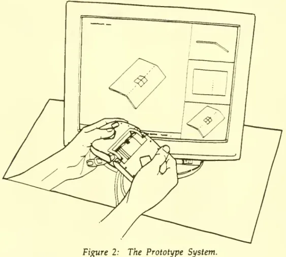
of the input device the virtual input device.)4.1
System
DescriptionThe
system
hastwo
major components:
a display screenand
a tool-like input device, asshown
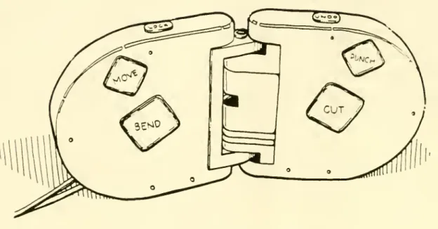
in Figure 2.The
display screenshows
animage
of the part to be designed.The
input device (Figure 3) has threemain
components:
the leftbody
section, the right
body
section,and
the hinge assembly.Each
body
section contains severalmomentary
switches that enable users to selectand
perform
desired designfunctions.
The
hingeassembly
hastwo
degrees of freedom: thetwo body
sectionsmay
be either rotated or translated relative toone
another.Figure 2: The Prototype System.
The
spatial position of the input device is relayed to thesystem
softwareby
aPolhemus
3Space
sensormounted
in the rightbody
half. This sensormeasures
theinformation is required
by
the design functions tomap
the virtual icon to the actualinput device.
Figure 3: The Input Device
A
small virtual input device icon, similar inshape
to the actual input device, isshown
on
the virtual sheet metal piece.The
icon iscomposed
oftwo
rectangles,which correspond
to thetwo
halves of the tool. This iconmay
be
moved
about theplanes of the virtual material
by
the user. Operations areperformed
on
the part at the positionand
orientation of this virtual icon.The
system
allows engineers to create partsby
performing
various production-like operationson
the virtual piece of sheet metal using the tool. Tactileand
spatialinputs received
from
the device are interpreted as functioncommands
by
the system's software.The
functions available to the user are:•
Bend:
Pressingand
holding thebend
buttonon
the input deviceand
bending
the
two
halves of the input deviceperforms
abend
in the sheet metal at the positionand
orientation of the virtual icon.The bend
function is interactive;a
change
in the angle of the input device causesan
associatedchange
in the design representation.As
the metal is bent,two
physical constraints areensured: the given
bend
radius isimplemented
and
theamount
of material in the sheet of metal is conserved.• Stretch: Pulling apart the
two body
halves causesnew
sheet material to beadded
along the axisdetermined
by
the virtual icon. This function finds all points of the sheet metalon
one
side of the virtual icon axisand
moves
those points in thesame
direction.The
resultingchange
providesmore
than asimple stretch of metal.
Using
the Stretchand
Shrink functions, practicallyany deformation
which
occurs in the plane of the sheetand
does
notchange
the
number
ofedges
and
vertices can be accomplished.• Shrink:
Pushing
thetwo body
halves together causes sheet material to beremoved
along the virtual icon axis in amanner
similar to the stretchfunction. Both stretch
and
shrink violate a strict productionmetaphor,
butappear
to be very useful. Both stretchand
shrink are naturaland
intuitiveoperations
on
a sheet of metal.• Cut:
Pushing
the cut button causes the icon tochange
to a red lineanchored
at the initial position of the icon.As
the usermoves
the input device inspace, the cut line
moves
around
the screen, butremains
anchored
to the sheet metal.When
the user releases the cut button, the cut isimplemented.
The
cut has awidth
that is presetby
the user.•
Punch
(currentlyunimplemented):
Pushing
thepunch
button will cause amenu
ofpunch
outlines toappear
on
the screen.The
user selects the desired outlineand
places the center point in the desired place.The
punched
hole can bemoved
interactively after initial placement.•
Move:
Pressingand
holding themove
button allows users tomove
the virtual icon along the planes of the virtual sheet metal design.Movements
and
rotations in space aremapped
tomovements
and
rotations of the iconon
the virtual sheet.
• Lock: Pressing the lock button "locks" the virtual sheet to the icon, so that
is selected often
by
users to helpunderstand
the three-dimensionalshape
ofthe part being designed.
•
Undo:
Pressing theundo
button restores thegeometry
of the virtual designto the state preceding the
most
recentlyimplemented
function.The
system
hasbeen
a vehicle for exploring our central research ideas, but there aremany
other featuresand
functions thatwould
be required before thesystem
could beused
to design parts in industrial practice. In particular,we
have
notimplemented
any
way
to 1)make
curved
cuts, 2)impose
parametric valueson
thepart dimensions, 3)
add
dimensional
information togeometry,
or 4)produce
two-dimensional
shop drawings from
three-dimensional models.These
features should be incorporated intoour
system
if it is tobe
useful inan
industrial setting.5.
Discussion
In this section
we
highlightwhat
was
learnedfrom
the construction of theprototype.
We
first discusshow
efforts like these canbe
evaluated.We
then presentwhat
we
believe are thekey
features of the system. Finally,we
propose
afew
directions for
improvement.
5.1 Evaluating Prototype
Systems
To
evaluate the system,we
demonstrated
it to engineers, engineeringmanagers,
and
researchers.Benchmarking
againstcommercial
CAD
systems
is inappropriateas the
system
lacks fullCAD
functionality.The
demonstrations
were
valuable asthey elicited insightful
and
sometimes
surprisingcomments.
The
demonstrations
thus
provided
agood
early test of thesystem
concept.We
plan tobenchmark
thesystem
againstcommercial
CAD
systems
in the future.We
will use the informationgained
in thedemonstrations
toenhance
thesystem
and
todevelop hypotheses
forbenchmarking
studies.Some
of thekey
features ofthe
system
and
some
ideas forsystem
enhancements
that arosefrom
thedemonstrations
are presented next.5.2
Key
Features of theSystem
The two
major advantages
of thesystem
over existing alternative concepts are ease of useand
part producibility.The
system
is easy to use.Although
we
have
notconducted
any
controlled experiments,we
have observed
that withone
ortwo
minutes
of explanation, a novice user can create a producible sheet metal part design with the system.We
attribute ease of use to thesystem
metaphor
and
to thedesign of the input device.
The
system metaphor
is of a production process. Bend,punch,
and
cut are directly analogous to the production operations forCNC
sheet metal cuttingcombined
withmanual
press brake bending. Stretchand
shrinkdo
nothave
common
analogies forblanked
and
bent sheet metal parts, but they areintuitive physical operations. This
metaphor
makes remembering
thesystem
commands
extremely simpleand
contributes to the ease of production of theresulting parts.
The
design of the input device alsomakes
thesystem
easy to use.There
are only afew
operations that can beinvoked by
the userand
they are all acombination
ofnatural
hand
motions
and
visible button actions.Bending
the input device results inbending
the part,moving
thehands
results inmovement
of the virtual input deviceon
the screen.Holding
the cut buttonand
moving
thehands
results in a cutting of the part. All of these actions are directly analogous to theway
a real toolmight
beused
tomodify
a real partand
therefore are easy toremember
and
invoke.The
undo
feature furtherenhances
usability.The
second major advantage
of the system, part producibility, isensured
by
both theproduction
metaphor and by
the production constraints.The
productionmetaphor
for design constrains the user to create physically realizable parts. There is
no
possible
combination
ofcommands
that will result in a design with a face that is notclosed or a line dangling in space. Production constraints also help to ensure that
notonly will the design
be
physically realizable, but that it can bemade
by
the sheetmetal process.
The
system
imposes
production constraints primarily in thebend
function.
When
bending, the radius of thebend
is specifiedby
aprogram
parameter.
When
thebend
radiusparameter
is properly set, the user can not create abend
radius that is not realizableby
thebending
process.An
additional constraintimposed by
thesystem
is thatbends
can not bemade
acrossan
existing bend.The
goal ofimposing
part producibilitywas
violatedby
the stretchand
shrink functions.With
these functions, it is possible to create a part that will not unfold to a flat sheet, e.g. a tab couldbe extended
such that if unfolded itwould
overlap theof part
dimensions
at theexpense
of this potential problem. This could be addressedby
automaticallymonitoring
this conditionand
alerting the designerwhen
the part canno
longer be unfolded to a flat sheet.5.3
Suggestions
forImprovement
There
are anumber
ofways
inwhich
thesystem
can beimproved.
We
will discuss sheet-metal-specificimprovements
here, but believe that the substance of the ideas applies tomany
designdomains.
• Intermediate part
geometry:
Sheet metal parts areformed by
blanking (cutting)then bending. Being able to
perform
operationson
theunbent
sheet metal partwould
facilitate the design activity. In effect thiswould
allow the designer toview
partgeometry
atan
intermediate point in its production process.Operations
performed
on
either the bent orunbent
sheetwould
causechanges
in both sheets. This feature, for
any
CAD
system,would
allow the user toevaluate constraints
which
apply
to parts at different points of the production process.•
Performance
evaluation:A
costmodel
of the sheet metal production processwould
help the engineermake
trade-offsbetween
cuttingand
bending, orbetween
scrap costsand
bending
costs.Other
types ofperformance
evaluation,like stress
and
weight,would
alsobe
useful.•
Production
constraints:The
system, as currentlyimplemented,
hassome
default values for design operation parameters. Forexample,
aminimum
bend
radius is definedand
canbe changed
for different types of sheet metal.Similarly, a default cut
width
has alsobeen
defined.Other
defaultcharacteristics for other functions could
be
definedand
incorporated into the system. Forexample,
some
manufacturing
processes for sheet metalbending
require a
minimum
distancebetween
bends. Thisminimum
distance could beset
and
violations flagged.The
result is that the user automatically operates within design constraintsand
ismade
aware
of violations as they occur.Another
type of producibility constraint thatmight be
useful is toimpose
parallelismand
perpendicularityon
cutsand
bends. Thiswould make
partseasier to produce. Since this constraint
must
often be violated in practice, this featuremight
beimplemented
as a user option.•
Automation:
Itmay
be possible toautomate
some
aspects of sheet metal design,and
use thesystem
interface only for non-routine or other types of design notamenable
to automation. For example, it is possible toautomate
the design ofsome
types of sheet metal bracketsby
specifying the position, orientation,and
shape
of the interfaces of the bracket to other parts, as well as the other objects(such as other parts, tubes, cables, etc.) that the bracket
must
not intersect with.The
system
couldautomate
the design ofmany
of the simpler sheet metal brackets in a given design,and
leave themore
difficult brackets to the engineer.6.
Summary
Engineering design is
complex
work
involving the juggling of a great deal ofinformation,
such
ascustomer
needs, process limitations,and
material constraints.This can lead to a situation in
which
engineers areoverwhelmed by
designcomplexity
and
do
not catchand
correct design flaws. Economicallypunishing
and
even
tragic failures can result.We
have argued
that the complexity of design canbe reduced
by
incorporatingmore
designknowledge
into the functionality of theCAD
system
and by
reducing the complexity ofCAD
system
operation.These
goals canbe
achievedby
utilizing aproduction-like design
metaphor,
by
providing design evaluation,by embedding
well
understood
constraints,by
automating
detailed design tasks,and
by
incorporating natural
mappings
into theCAD
system
controlsand
display.We
built a research prototype to test these ideas.We
learned that the productionmetaphor
and
theergonomics
ofour
spatial-tactile input devicecombine
tomake
the
system
very easy to learnand
use.We
believe that, inan
industrial setting,constraints like those
we
placedon
thebend
operation can contribute toenhanced
part producibility.
Demonstrations
of the prototypeprovided
ideas forenhancements
to the system.Much
couldbe
done
to further ease the cognitiveburden on
the engineer.More
researchand
system
development
isneeded
to refine the design goalswe
have
We
believe that the resultingCAD
systems willsupport
the engineermore
effectively, allowing a focus of attentionon
critical or creative design tasks.Bibliography
Adler, P.A.
"Managing
High
Tech
Processes:The
Challenge ofCAD/CAM."
inVon
Glinow and
Mohrman
(ed.)Managing
Complexity inHigh
Technology Organizations,New
York:Oxford
University Press, 1990.Barfield, W., J. Sanford
and
J. Foley. "TheMental
Rotationand
Perceived Realismof
Computer-Generated
Three-Dimensional
Images." International Tournal ofMan-Machine
Studies, Vol. 29 (1988): pp. 669-684.Bemis, S.V., J.L. Leeds,
and
E.A. Winer. "OperatorPerformance
as a Function ofType
of Display:Conventional
Versus Perspective."Human
Factors. Vol. 30,No.
2 (April 1988): pp. 163-169.Bull, R.J.
"Concept
to PrototypeUsing
Computing
Techniques," Proceedings of theInstitute for
Mechanical
EngineersConference
on
EffectiveCADCAM
'87/Towards
Integration,
November
1987.Calkins, D.E.
and
J. Ishimaru."Computer
Graphicsand
Animation
Come
to ShipDesigning,"
Computers
inMechanical
Engineering, Vol. 3,No.
1 (July 1984): pp. 33-42.Computer
Aided
Design
Report. Vol. 10,No.
5(May
1990).Computer
Graphics World.
"A Roundtable
on
SolidModeling"
June, 1988: pp. 41-51.Crombez,
G.R. "Chrysler Builds a BetterNetwork."
Manufacturing
Systems, Vol. 6,No.
3(March
1988): pp. 44-51.Cutkosky,
M.R.
and
J.M.Tenenbaum
"CAD
/CAM
IntegrationThrough
Concurrent
Process
and
Product
Design," Proceedings of theASME
Winter
Annual
Meeting
Symposium
on
Intelligent IntegratedManufacturing
Analysisand
Synthesis, 1987:pp. 1-10.
DeMatthew,
T. "Productivityby Computer-Aided
Design."Automation,
Vol. 36,No.
1 (Jan. 1989): pp. 52-54.Dutton, B.
"More
TalesFrom
the Factory Floor."Manufacturing
Systems, Vol. 4,No.
7(July 1986): pp. 38-42.Eade, R.
"Screw
Machining:An
Industry withNine
Lives."Manufacturing
Engineering, Vol. 100,
No.
6 (June 1988): pp. 73-76.Farrar, D.J.
"CADCAM-
Productive or Counterproductive?" Proceedings of the Institute forMechanical
EngineersConference
on
EffectiveCADCAM
'87/Towards
Filennan,
M.C.
"Design of aThree-Dimensional
Tactile InputDevice
forMechanical
CAD."
Master
of Science Thesis, Massachusetts Institute ofTechnology
Department
ofMechanical
Engineering,May
1990.Fitzgerald, K.
"Compressing
theDesign
Cycle,"IEEE Spectrum,
Vol. 24,No.
10 (Oct. 1987): pp. 39-42.Frangini,
M.
"RacingTeam
Relieson
CAD/CAM
toSpeed
Up
Design
Process,"Computing
Canada,
Vol. 16,No.
17(August
16, 1990): pg. 10.Krouse, J. R. Mills, B. Beckert,
and
C. Potter."CAD/CAM
Planning Guide:Do
Benefits
Outweigh
Costs?"Machine
Design, Vol. 61,No.
15 (July 20, 1989): pp. S6-S12.Lansiaux, P.
"CADCAM
in Rolls-RoyceAero
Engines," Proceedings of the Institute forMechanical
EngineersConference
on
EffectiveCADCAM
'87/Towards
Integration,
November
1987.Machover,
C
and
R.E. Blauth. TheCAD/CAM
Handbook.Computervision,
Bedford,
MA:
1980.Majchrzak, A.
and
H.Salzman.
"Socialand
OrganizationalDimensions
ofComputer-Aided
Design."IEEE
Transactionson
EngineeringManagement,
Vol.EM-36, No.
3(Aug
1989): pp. 174-179.Manji, J.F.
"Time
toMarket
is Critical."Automation,
Vol. 36,No.
7 (July 1989): pp.36-41.
Mantyla,
M.
An
Introduction to Solid Modeling. Rockville,Maryland:
Computer
Science Press, 1988.McKim,
R.H. Experiences in Visual Thinking. Boston:PWS
Publishers, 1980.Miller, G.
"The Magical
Number
Seven, Plus orMinus
Two,"
PsychologicalBulletin, Vol. 63 (1956): pp. 81-97.
NASA
Technical Briefs,August
1989.Norman,
D.A. The Psychology of Everyday Things.New
York: Basic Books, 1988.Pentland, A.P.
"Towards
an Ideal3-D
CAD
System," inImage
Understanding andthe
Man
Machine
Interface, Artificial Intelligence Center,SRI
International,Menlo
Park,CA.
SPIE
Vol. 758, 1987.Pratt, M.J. "Solid
Modeling
and
the InterfaceBetween Design and
Manufacture,"IEEE
Computer
Graphicsand
Applications, Vol.CGA-4,
No.
7 (July, 1984): pp. 52-59.Roberts, A. "3-Draw:
A
Three-Dimensional
Computer
Aided
Design
Tool," Masterof Science Thesis, Massachusetts Institute of
Technology
Department
ofMechanical
Engineering,
December,
1989.Salzman,
H."Computer-Aided
Design: Limitations inAutomating
Design and
Drafting."
IEEE
Transactionson
EngineeringManagement.
Vol.EM-36, No.
4(Nov
1989): pp. 252-261.
Schmandt,
CM.
"Spatial Input/DisplayCorrespondence
in a StereoscopicComputer
Graphic
Work
Station."ACM
Computer
Graphics, Vol. 17,No.
3 (July, 1983).Shepard, R.N.
and
C. Feng."A Chronometric Study
ofMental Paper
Folding." Cognitive Psychology, Vol. 3 (1972): pp. 228-243.Shepard, R.N.
and
J. Metzler. "Mental Rotation ofThree-Dimensional
Objects."Science, Vol. 171 (1971): pp. 701-703.
Simon,
H.A.
The Sciences of the Artificial (2nd Edition).Cambridge,
MA:
The
MIT
Press, 1981.Smith, D.
"CAD/CAM
ProductivityTime
Ratios for VariousDrawing
Types," Society ofManufacturing
Engineers, Dearborn, MI,Mar,
1982.Teresko, J. "Speeding the
Product
Development
Cycle." IndustryWeek,
Vol. 237,No.
6 (July 18, 1988): pp. 40-42.Teresko, J.
"A
Report
Card on
CAD/CAM."
IndustryWeek,
Vol. 239,No.
6(March
19, 1990): pp. 44-50.
Vasilash, G.S. "Sheet Metal Processing: Sophisticated Simplicity." Production, Vol. 100,
No.
4 (April 1988): pp. 53-58.Velocci, T.
and
J. Childs "French Aerospace: Global Leadership." AviationWeek
and
Space
Technology, Vol. 133,No.
9(Aug
27, 1990): pp. S5-S24.Voelcker, H.B.,
A.A.G.
Requicha,and
R.W.
Conway,
"Computer
Applications inManufacturing,"
Annual Review
ofComputer
Science, Vol. 3 (1988): pp. 349-387.Waldern,
J.D., A.Humrich,
and
L.Cochrane
"StudyingDepth Cues
in aThree-Dimensional
Computer
Graphics
Workstation." International Tournal ofA
ppendix
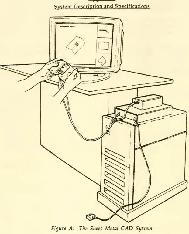
System
Descriptionand
SpecificationsFigure A: The Sheet Metal
CAD
SystemThe
system
isshown
in Figure A. Below, the softwareand hardware
specifications of thesystem
are described.Software
The
system
software is written in theC
programming
language
using calls toSunPHIGS
version 1.1The
system
represents sheet metal using a fullwinged-edge
data structure (Mantyla1988). Sheet metal data is represented as vertices, edges connecting vertices,
and
faces
composed
of linked lists of edges.Hardware
The
software runson
aSun
4-330SPARC
workstation. This 32-bitRISC-based
computer
isequipped
with aCXP
hardware
graphics accelerator using an 8-bit framebuffer.
A
Polhemus
3Space
Isotrak SensorSystem
4is
embedded
in thehand-held
input device. This sensor transmits three-dimensional orientationand
rotation information to theSun
computer'sRS-232C
serial port at 19200 baud.Inputs
from
the push-buttonsand
thebend
sensor potentiometeron
the input device are delivered to thecomputer through
aData
Translation 1414 InterfaceBoard. This
VMEBus
board
isequipped
with a 12-bit analog-to-digital converter.The
input device relays both analogand
digital data to thecomputer through
this board.Date
Due
mu
MIT LIBRARIES DUPL