HAL Id: hal-03042600
https://hal.archives-ouvertes.fr/hal-03042600
Submitted on 23 Dec 2020HAL is a multi-disciplinary open access
archive for the deposit and dissemination of sci-entific research documents, whether they are pub-lished or not. The documents may come from teaching and research institutions in France or abroad, or from public or private research centers.
L’archive ouverte pluridisciplinaire HAL, est destinée au dépôt et à la diffusion de documents scientifiques de niveau recherche, publiés ou non, émanant des établissements d’enseignement et de recherche français ou étrangers, des laboratoires publics ou privés.
Influence Of Fracture And Delayed Effects On
Steel-Concrete Composite Structures
Fery Léo, Gwozdziewicz Piotr, Rostand Moutou Pitti
To cite this version:
Fery Léo, Gwozdziewicz Piotr, Rostand Moutou Pitti. Influence Of Fracture And Delayed Effects On Steel-Concrete Composite Structures. Fracture, Fatigue, Failure and Damage Evolution, 3, 2021, Frac-ture, Fatigue, Failure and Damage Evolution, Conference Proceedings of the Society for, �10.1007/978-3-030-60959-7_1�. �hal-03042600�
Influence Of Fracture And Delayed Effects On Steel-Concrete Composite
Structures
Fery Léo
1, Gwozdziewicz Piotr
2, Moutou Pitti Rostand
1,31
Université Clermont Auvergne, CNRS, Institut Pascal, BP 20206,
F-63000 Clermont-Ferrand, France
2
Facukty of Civil Engineering, Politechnika Krakowska,
Warszawska, 31-155 Krakow, Poland
3
Institut de Recherche Technologique
CENAREST, BP14070, Libreville, Gabon
ABSTRACT
This work investigates the fracture behavior of Preflex beams submitted to time dependent effects and long term loadings. However, it is necessary to consider delayed effects such as shrinkage and creep on these structures because their influence is not negligible. The different materials used in mixed construction are presented. The flowchart applied to compute creep and relaxation effects versus the time is also described. It is interesting to note that the analytical results obtained for a Preflex beam are very similar to those obtained using finite element modelling on the LUSAS software. It is also observable that the cracking of the concrete that encases the lower fibre, due to creep, causes an increase of stresses in the steel profile that can lead to the break of the beam. The use of reinforcement on the preflex beam decrease the crack opening after 100 years loadings.
Keywords: Steel-concrete composite structure, Creep, Shrinkage, Fracture, Preflex beam INTRODUCTION
Mixed construction is a method which knows a quick development and takes advantage of two materials: steel and concrete [1-2]. They are linked together by connectors, so that concrete works in compression and steel in tension. This results in a composite beam with improved mechanical characteristics because both concretes are supposed to work in compression. However, it is necessary to consider the impact of delayed effects such as shrinkage and creep on the fracture processes of these structures because their influence is not negligible.
The literature background show that some authors discussed about the behavior and the manufacturing process of preflex beam [3] [4]. Foort [5] studied the behavior of connectors in preflex beams due to normal and rupture force. Jerome [6] investigated Study the cracking of stressed preflex beams by comparing numerical and analytical results given by Ghali and Fabre method [7]. But the impact of delayed effects as creep and relaxation of crack process have not investigated in this structure.
The different materials used in mixed construction are presented. In the same time, the conception step of the preflex beam and the numerical flowchart to obtain crack opening is described. It is also observable that the cracking of the concrete that encases the lower fibre, due to creep, causes an increase of stresses in the steel profile that can lead to the total collapse of the beam.
MATERIAL AND METHODS
Materials : Preflex beam
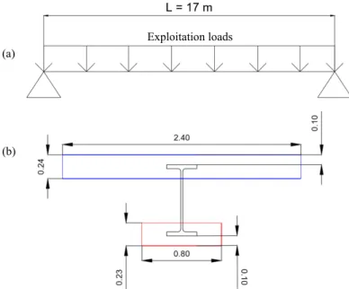
The Preflex beam is studied in the rest of this study. An isostatic beam with a span of 17 m was considered subject to a variable operating load, Figure 1 (a). The section consists of a HEM 700, first phase concrete B1 (in red) and second phase concrete B2 (in blue), as can be seen in Figure 1 (b). All dimensions are given here in meters .
Figure 1: (a) Static model of the beam. (b) Section of beam studied
According to table 1 (a), a shade of 275 MPa has been chosen. The elastic moment of the profile is 2299 kN.m. Concrete B1 and B2 are respectively C50 / 60 and C25 / 30 as posted in Table 1 (b).
Table 1: (a) Characteristic of the profile HEM 700. (b) Characteristics of the concrete in B1/B2 phases (a)
(b)
Exploitation loads
(a)
(b)
Mechanical characteristic of steel
Characteristic of concrete Concrete B1 Concrete B2 Resistance Class Class of cement Resistance Class Class of cement Class N Class N
For numerical computation, a load of 7 kN / m² applied to the entire upper surface of concrete B2 is applied. The relative humidity of the environment has been assumed to be 70%.
Modelling steps
The different steps of the building are posted in Table 2. Concrete B1 is poured on day 1 and concrete B2 on day 31. In fact, we wait 28 days after pouring B1 before releasing the pre-bending forces and 28 days after pouring B2 before commission the beam.
Table 2: Preflex beam manufacturing steps
The pre-bending force is composed of two point forces: one located at the quarter of the beam and another located at the three-quarters. It is necessary that the profile does not exceed its elastic limit during the pre-bending step.
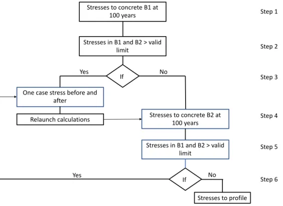
In order to calculate the rupture load of the Preflex beam in both cases (with and without the delayed effects), we will increase the operating load until the rupture stress of the profile is reached. The finite element software LUSAS is used in order to implement the numerical model. An important assumption which consists in supposing that the concrete B1 does not work anymore and can be removed when it is completely cracked. It should be noted that the concrete B1 cracks because the loading is important. In general, this concrete is used in Preflex beams for its toughness in compression. When the complete cracking appears we denote two load cases: one before the total cracking and one after. For the second load case (after cracking), we remove the concrete B1 and add a linear force representing the self-weight of B1 before restarting the calculation. Thus, for each load case (the load is gradually increased), we proceeded as follows detailed in flowchart of Figure 4 as follow:
• Step 1. First, we list the lower and upper fiber stresses in concrete B1 at 100 years. • Step 2. It is then checked whether these values exceed the admissible stress.
• Step 3. If this is the case, we are looking for the date on which concrete B1 is completely cracked. If this is not the case, we go directly to step 6.
• Step 4. Two load cases are created: one before cracking and one after the removed of concrete B1 by adding its own weight.
• Step 5. We relaunch the calculations and we list the stresses suffered by concrete B2 at 100 years because removing concrete B1 increases the stresses in the profile and in concrete B2.
• Step 6. We check that the concrete B2 does not reach its admissible limit and we proceed in the same way as for B1 if this is the case. Finally, we list the maximum stress in the steel profile and check that it remains acceptable.
Stapes Tasks Days
1 Profile preflexion 0
2 Consideration of delay effects of concrete B1 29
3 Relaxation of the preflexion loads 30
4 Consideration of delay effects of concrete B2 59
5 loading 60
Figure 2: Flowchart for computing the rupture stress
RESULTS AND DISCUSSION
Crack opening with first reinforcement
The fracture due to creep and relaxation effects have been discussed in this section. The applying force is 22 kN/m² (breaking load of the beam when we do not use reinforcing steel taking up traction in concrete) at the serviceability limit state.
Figure 3: Crack opening due to creep / relaxation effects with first reinforcements Stresses to concrete B1 at
100 years
Stresses in B1 and B2 > valid limit
If No
Yes One case stress before and
after
Stresses to concrete B2 at 100 years Relaunch calculations
Stresses in B1 and B2 > valid limit If No Yes Stresses to profile Step 1 Step 2 Step 3 Step 4 Step 5 Step 6 Cr ac k op en in g (m m ) 0 0,1 0,2 0,3 0,4 0,5 0,6 100 1000 10000 100000 Time (days) Creep Shrinkage
The consideration of cracking of concrete under LUSAS, is computed by using steel reinforcements. We therefore started by applying a very weak reinforcement, composed of 6 mm bars every 30 cm, in the longitudinal and transverse direction of the beam, on the upper face and on the lower face.
Figure 3 presents the relationship between the crack opening versus time for the creep and the shrinkage effects. It observed that crack opening due to creep is significantly greater than that due to shrinkage. Indeed, at 100 years, creep represents 77.6% of cracking after loading and shrinkage only 22.4%. On the graph, we can notice that even at 100 years, the cracking induced by the shrinkage continues to increase very slightly whereas it is completely stopped for creep.
Figure 4: Crack opening due to creep / relaxation with second reinforcements
Crack opening with second reinforcement
In order to decrease the impact of delay deformations on crack opening, the reinforcement have been increased. In this case, bars of 6 mm every 15 cm were placed on the upper side and bars of 12 mm every 15 cm on the lower side. Figure 4 presents the relationship between the crack opening versus time for the creep and the shrinkage effects. This reinforcement of steel allows to remain below the admissible limit of cracking, since when we take into account the cracking due to loading and that due to delayed effects, we arrive at 0.08 mm at 100 years. Once again, we realize that the cracking due to creep is much greater than that due to shrinkage. The proportion remains the same since 77.6% of the cracking due to delayed effects comes from creep.
CONCLUSION
In this work, the behavior of preflex beam is investigated. The different materials used in the design of this structure is presented. The design step and the numerical implementation of crack opening with LUSAS software is detailed. The crack processes due to creep and shrinkage effects are investigated. It is observed that the use of reinforcement decrease
significantly the crack opening even if the creep is responsible of more than 77 % of the crack opening process. From these results, it can be concluded that the consideration of delayed effects leads to a lower failure load of the beam. Therefore, it is necessary to consider the delayed effects in the dimensioning of a Preflex beam in order to avoid the total collapse of the structure. Cr ac k op en in g (m m ) 0 0,01 0,02 0,03 0,04 0,05 0,06 0,07 0,08 0,09 100 1000 10000 100000 Creep Shrinkage Time (days)
REFERENCES
[1] Aribert JM. Construction mixte acier-béton : Calcul des poutres mixtes. Techniques de l’ingénieur. Novembre 2004 [2] Aribert JM. Analyse et formulation pratique de l'influence de la nuance de l'acier du profilé sur le degré minimum de
connexion partielle d'une poutre mixte. Revue construction métallique n°3. 1997
[3] Bae D., Lee, K. Behavior of preflex beam in manufacturing process. KSCE J Civ Eng. 8, 111–115, 2004 https://doi.org/10.1007/BF02829086
[4] Foort E. Connecteurs dans les poutres Preflex : comportements dus à l’effort normal et à l’effort de rupture –
Mémoire de fin d’étude, Polytech Clermont Ferrand. Politechnika Krakowska, 2016
[5] Ghali A., Fabre R. Concrete structures : stresses and deformations. Seconde Edition, 1994
[6] Jerome M. Étude de la fissuration des poutres Preflex sollicitées. Comparaions numérique et analytique. Mémoire de
fin d’étude, Polytech Clermont Ferrand, Politechnika Krakowska – 2011
[7] Zhang K.; Li S., Liu K. Experimental Study on Static and Fatigue Behavior of Steel-Concrete Preflex Prestressed Composite Beam. Advances in Steel Structures (ICASS '99). Proceedings of The Second International Conference on Advances in Steel Structures 15–17 December 1999, Hong Kong, China Volume II, 1999, Pages 965-973