FORMALIZING THE MENTAL MODEL
OF A SOFTWARE ARCHITECTURE
DALILA GUESSOUM* and DJAMEL BENNOUAR**
Department of Computer Science, University Saad Dahleb, Blida, Algeria *[email protected], **[email protected]
ABSTRACT
This paper presents the main concepts of a specification approach which operates at the architectural level in the development process of a software solution. The specification approach has the capacity to deal directly with the first ideas, called mental model, of a software solution. The approach is mainly based on a graphical editor which enables software architects to directly specify their first ideas which are usually informal. The graphic editor, called IASA STUDIO, then transforms informal specification to a formal specification specified in an Architecture Description Language (ADL) called X3ADL. The X3ADL specification represents the starting point for a model transformation process which leads to an implementation view of a software in a chosen implementation technology.
Keywords: Software architecture; IDE; ADL; Model transformation; Code synthesis.
1. INTRODUCTION
With the emergence of large communication networks, new applications become increasingly distributed, large with a complex architecture. This complexity is due to necessary and permanent scalability requirements, to hardware and software heterogeneity and to the high degree of interaction between different software entities constituting the application. To better manage the complexity of such applications, it is recommended to have a high level of abstraction [13] and to have models that approach the developer's mental model. A possible answer is the definition of software architecture systems. Software architecture describes the set of components that compose the system, defines their assembly and considers the features needed for the deployment and the exploitation of the resulting system [12].
Practitioners have realized that having proper software architecture is a critical success factor for the design and development of systems [6]. Although there are several interesting proposals at both the architectural models and specification languages for software architecture, these proposals lack flexibility and reveal several differences both in the semantics of concepts but also in approaches to specification. Indeed there are a multitude of ADLs (Architecture Description Language) in academia and
industry. Some examples are Wright, Darwin, ACME, AADL, ArchWare, etc. The concepts of components, connectors and configurations are addressed in different ways depending on the language.
Our work finds its origins in the inability of current models to support the specification of software architectures such as done in the early step of a software elaboration process. Indeed, what is observable now in the process of formalizing the specification of software architecture, is the fact that current ADLs do not support the specification of software architectures such as made in the initial phases. This is mainly due to the fact that ADLs depend strongly in the specification of software architectures for basic mechanisms, including the concepts of interface and the concept of procedure call or transaction. Specifications in the initial phases can be independent of these two mechanisms. This may explain the difficulty of developing more efficient software systems, and more particularly to generate the source code matching those kinds of systems whose complexity and diversity of used technologies are characteristics of the latter.
To overcome these limitations, we believe that it is wise to take advantage of advances in recent software engineering techniques. In this context, the most suitable engineering technique seems to be the model-driven engineering (or MDE), which designs the entire life cycle as a process of production, of iterative refinement and integration of models. The use of models allows us to capitalize on the knowledge and expertise at different levels of abstraction [5, 9]. It thus covers the different views of the system by moving from an abstract model to a model specific to the system environment to develop [11, 14]. This approach ensures consistency of the system during the different phases of the lifecycle.
Our contribution in this paper consists in developing an approach for specifying software architecture in a highly flexible manner. The desired flexibility consists in supporting the direct specification of mental models of the architect. This specification is very close to the informal one. A first transformation from an informal specification to a formal specification represented by an ADL is required. The system that handles the capture of the mental model is an integrated development environment (IDE) called IASA_STUDIO, which is provided with capabilities for specification, verification, and transformation of the architecture into an executable code.
The 13th International Arab Conference on Information Technology ACIT'2012 Dec.10-13
ISSN : 1812-0857
This paper is organized as follows. Section 2 presents the mental model of a software architect. Section 3 provides an overview of the behaviors of the architect during the specification of architecture. Section 4 and section 5 present the fundamental concept of our approach to support the mental model of a software architect. In Section 6 we present the main features of IASAStudio. Finally, in Section 7 we conclude our article with a conclusion and with some perspectives to this work.
2.THE MENTAL MODEL OF A SOFTWARE
ARCHITECTA specification of software architecture represents the first ideas that an architect makes of his system. This specification has often a graphic form in which we find rectangles and links. Sometimes instead of using a rectangle to represent a system part or component, the architect uses a specific shape such as a cylinder to represent a database. The specific shape provides information from their view on the overall functionality of the associated component. The graphical specification is often a very abstract view of the system. It corresponds strongly to what we call the mental model of the architect. The mental model is inherently graphical. The document referring the mental model represents a document that can also involve the client to specify in a more precise manner his requirements or to indicate strategic choices.
A software architecture that comes from the mental model can be more abstract than the PIM (Platform Independent Model) of MDA. The mental model is not only independent of platform, but can be independent of software mechanisms, including those dedicated to interactions.
To find the models that could effectively accommodate the elements of the informal specification and the various architectural decisions, it is necessary to understand what really does an architect during the specification of the mental model and also during the phases where a solution begins to become more formal. In the next section, we will try to highlight the various behaviors, mainly the architectural decision, of an architect during the elaboration process of the architecture of a software solution.
3.THE BEHAVIORS OF THE ARCHITECT
DURING THE SPECIFICATION OF AN ARCHITECTUREArchitecting is actually an art that depends fundamentally on the architect reasoning. Thus, it is very possible for a simple solution, that two architects may have totally different reasoning in the specification of their architecture [7]. The differences can be mainly at the development approach (from the global to the detail or the detail to the global), the choice of building blocks (components) and the techniques used to specify the various interconnections between them. Architecture is an art. A graphical editor must allow a high degree of freedom in the operations of
specification of an architecture in which there is no need to find the rigor imposed by other approaches of software architecture (i.e. define the interfaces before binding them, bind only fully compatible interfaces).
3.1
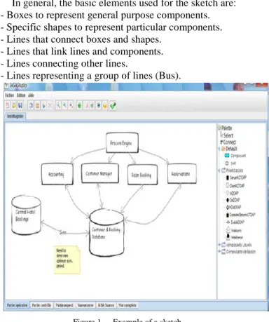
ARCHITECTURAL ELEMENTSDuring the first specification, the architect develops a sketch that is not really precise. Then this sketch will be refined with comments at the component and links level (Figure 1). Before starting the next stage of the development process, the architect performs manually or by using tools, an evaluation of his sketches to ensure that they meet customer requirements.
In general, the basic elements used for the sketch are: - Boxes to represent general purpose components. - Specific shapes to represent particular components. - Lines that connect boxes and shapes.
- Lines that link lines and components. - Lines connecting other lines.
- Lines representing a group of lines (Bus).
Figure 1. Example of a sketch
3.2 A
BSTRACT AND PRIMITIVE COMPONENTS Often the architect uses abstract component and indicates progressively its external view. He can also use components that have an existence and do not require study or implementation. They require only proper exploitation. These components, whatever their size are called primitive components. An HTTP server and a database server are primitive components. An adder or more precisely an operator in terms of a programming language is also a primitive component. The sketch may be a mixture of abstract components, which have to be realized, and primitive components.3.3
DRAWING CONNECTIONSWhen making connections between components, the architect operates without constraint by linking a first component to a second in a point to point connection. This binding is traced without any constraints. However, we note that the link always starts from a component or a link. In the case where the starting and ending points are the boundaries of two interconnected components, the link may represent three situations:
- The component containing the starting point may require a resource from the second component
- The second component may require a resource from the first component
- The link is a peer to peer connection: the first (or the second) requires a resource from the second (or the first) and also provides a resource for the second (first).
In such a situation, and in the formalization process of IASA_STUDIO, the type of the link, or connection, may be explicitly specified by the architect, using a context pop up menu associated with the just drawn connector. The connector type indicates clearly the provider (server) and the requester (client).
In the case where no information are added to the connector, the anticipation task of the formalization process fixes automatically the provider and the requester based on the starting point of the connector. The anticipation task considers the starting point as a resource requester point (client) and the ending point as a resource provider. The anticipation resolution process is actually a parameter of IASA STUDIO.
3.4
DRAWING COMPLEX ARCHITECTUREWhen specifying a complex architecture, the architect uses either a large sheet, able to see the entire architecture or small sheets, each dealing with one part of the overall architecture. Thus IASA_STUDIO must allow the specification in a single view (sheet) or in separate views. Moreover, IASA_STUDIO can cut a sheet into smaller sheets, according to the indications of boundary between the sheets. Therefore, IASA_STUDIO must be able to assemble small sheets in larger sheets and vice versa.
Throughout the process of refinement of architecture, various other architectural decisions are possible that we have not cited in this paper, however, in the next section, we present how it is possible within a flexible specification approach to software architecture to support and formalize these informal behaviors that represent the mental model of the architect.
4.THE BASIC GRAPHICAL NOTATIONS FOR
THE SPECIFICATION OF THE MENTAL MODELIn this section we try to define the graphical notations and actions for handling in a direct and effective manner the mental model of an architect. Generally, the specification of an architecture is essentially based on:
- A basic set of graphical elements.
- A large degree of freedom in the manipulation of these elements, particularly when making connections between different forms representing components.
The graphical notation must address the following elements:
- The component to be represented graphically by precise forms, including rectangles.
- Ports of interactions of the component. We call them ports to distinguish from the concept of interface and also to indicate that a port has a structure and that it is possible to manipulate individual elements of the port, which is not possible with interfaces.
- Simple connectors. - Buses.
In the specification process and transformation of the mental model to support various design decisions throughout the process of refinement of an architecture, we will use essentially the graphical notation defined in the IASA approach (Integrated Approach for Software Architecture) [3].
4.1
THE FUNDAMENTAL CONCEPTS AND MODELS IN IASAIASA is an approach to software architecture that allows the specification of aspect-oriented software architectures [3]. IASA defines a set of concepts that allows the specification of software architecture in a very flexible way with a high degree of freedom from any software mechanism constraint, allowing to specify the software architecture in a way that approaches the mental model of the architect. The full description of the approach IASA is detailed in [4].
The IASA approach is based on a unified component model oriented to support system design where some components may be deployed as software components and others as hardware components. IASA is based on the following concepts: access point, port, component, envelope, connector and action.
The component is a fundamental element in defining software architecture. The component model distinguishes between two broad categories of components: the primitive components and composite components.
The component model defines two views in a component, an external view which must adhere to any component and an internal view, applicable only to composites. The external view is represented by the concept of the envelope. The internal view is organized into two main parts: the operative part and control part, and one option part: the aspect part.
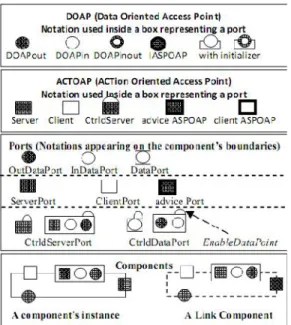
In IASA, a component interacts with the external world through a set of ports. A port has a structure made of access points and a behavior. The instantiation of a component is realized in the context of the envelope concept. An envelope is used to isolate the pure instance of a component from its operating environment by providing it with the necessary elements for the operation of the proceeding. The main graphic notations used by IASA are presented in Figure 2.
Figure 2. The main graphic notations in IASA [4]
IASA is based on a Specific ADL named 3ADL (Aspect, Action and Architecture Description Language) [2]. However the current form of this language covers only specific parts of the architecture specification. This is why we have defined an XML extension of this language called X3ADL (eXtensible Architecture, Aspect and Action Description Language).The X3ADL specification is the entry of a model transformation process that would lead to a view of the executable system.
4.2
NEW GRAPHIC NOTATION FOR IASAIASA notation is well suited for the transformation of an informal specification into a specification based on the IASA notation. However, in certain situations mentioned in the behaviour of the architect, this notation is not sufficient and new notations are required. The new notations deal with the following concepts:
Components: The shape associated to a component is unique and predefined in IASA. The enrichment of IASA on this aspect is to provide IASA STUDIO with a predefined library of forms, each associated with specific functionality. This library is extensible.
Connectors and bus: IASA uses the same notation for connectors: a line. There is no explicit distinction in terms of graphical notation between a connector linking ports and a connector linking access points. In addition, there is no notation for buses. In our proposal a connector is represented by a single line. A connector can only connect access points. A bus is represented by a thick line. A bus interconnects ports (Figure 3).
Figure 3. Proposed notation for connectors and bus in IASA Detailed view of an access point: A data access point (DOAP) conveys information that may be seen as a particular structure. The structure often brings outs the parts of information that can be considered independently of other parts. Thus a DOAP could be seen as a set of DOAPs, each oriented towards the support of a part of the information. The IDE of IASA provides mechanisms for the architect to see the details of a DOAP. The architect could put in evidence the internal DOAP of a DOAP. A DOAP whatever its depth may be used individually.
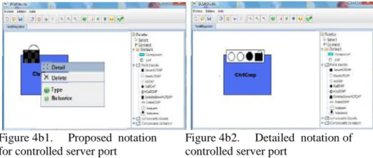
Controlled access point and ports: In the current version of IASA, a controlled access point or a controlled port has a graphical view in which the control is represented by a padlock. The padlock in reality corresponds to a given access point oriented (DOAP) which is not visible in the detailed notation, because even in the latter it is represented by a padlock. To allow a clear specification, and allow the specification approach to support a wide variety of architectural reasoning, we propose a new way of looking at controlled ports. We maintain the concept of padlocks associated with a port (or an access point) when the port is not seen in detail (Figure 4a1, Figure 4b1). When the detail of the port is requested, we propose to show explicitly the control mechanism, represented by a DOAP. The detail of a data point or controlled port explicitly shows the access point used as a control point (Figure 4a2, Figure 4b2). In the detail view the padlock disappears. With this new view, it is possible to explicitly link the control point to a data source .
Figure 4a1. Proposed notation for controlled data port
Figure 4a2. Detailed notation of controlled data port
Figure 4b1. Proposed notation for controlled server port
Figure 4b2. Detailed notation of controlled server port
Complex connectors: In IASA, a complex connector is represented by a communication component. This component has the same structure as a regular component. It is represented by a rectangle in which a number of ports are placed. Presenting a connector as a regular component could lead to ambiguity when reading architecture. We propose to maintain the view of component, but to introduce another notation as a thick line that is necessary to distinguish from ordinary bus. In IASA, there is actually an aspect that characterizes communication components. This aspect is the positioning of client ports and service ports. For example in a communication component dedicated to load balancing, the left side of the rectangle corresponds to the server ports and the right side corresponds to clients ports (Figure 5). In the IDE it is possible to move from a view as a component to a view as a line and vice versa.
Figure 5. Example of complex connectors
5.THE TRANSFORMATION PROCESS FOR IASA
The IASA approach, allows free specification of topologies of components in a high level of abstraction this is due to the concept of port that provides facilities for free specification without constraints. With respect to MDA approach, the component model and port are used to specify software system that can be positioned at a level of abstraction higher than the MDA PIM (Platform Independent Model) level since it is totally independent from any software mechanism.
The transformation process of a X3ADL specification into a specification in a very specific implementation technology starts with the graphical specification. This later is converted automatically or with assistance (the architect must provide additional information for making decisions at the step of interpretation of architectural decisions) in a
X3ADL description. The transformation process includes four steps:
- The formalization of architectural decisions: obtaining a X3ADL description from a free specification of software architecture similar to the informal specification with minimum of constraints. - Weaving aspects: This occurs when the
aspect-oriented design is implemented. This is a X3ADL to X3ADL transformation. In the generated form, the clauses relating to the oriented aspects specification are resolved and there is no oriented aspect clause in the X3ADL generated by this step.
- The normalization of the architecture. - The production of implementation view.
5.1
THE FORMALIZATION OF ARCHITECTURAL DECISIONSAs introduced earlier, an architectural decision concerns the choice of components, how to interconnect them to form the topology that the architect has in mind, how to specify various aspects of behavior, including interactions, the behavior of the components, the conditions to connect ports imposed by the components. The transformation at this level concerns architectural actions that seem to be part of the informal domain, such as deciding to connect two components by drawing a thick line (bus) or single line (connector), binding edge (border) of geometric shapes representing components or connect the border of a component to a connector or a bus.
The transformation rules applied depend on several factors including:
- The elements to be interconnected. - The standards of communication used.
- How the architectural decision is defined: Direction of the connector, description of the interactions. - An explicit choice of the architect.
This transformation process is done in real time, it is carried out progressively as the actions of the architect in the IDE, and the result of the transformation is immediately accessible to the architect. Thus for each action the IDE performs a transformation according to the conditions in which the architectural decision is specified. Under these conditions the architect may step in and adjust the transformation according to the requirements.
5.2
WEAVING ASPECTSWeaving aspects is mainly based on the concept of envelope. It is at this step that the port types of component are transformed by adding new access point called ASPOAP (Aspect Oriented Access Point). The transformation of these ports entails the creation of a new type of internal ports. The result of this phase is a X3ADL description in which operations of aspects injection are totally resolved.
5.3
THE NORMALIZATIONThe normalization phase allows determining a model at PIM level of MDA. This normalization transforms a X3ADL description into a description based on the concepts of
ordinary port and interface. We recall that the IASA port, unlike ports based on the concept of interface, allows the manipulation of any single structural or behavioral element. This is not the case in other approaches of software architecture in which the port, also called interface, is an atomic concept, which does not allow the manipulation of its components. The architecture which is constructed with the freedom to manipulate the access points (including DOAP) is not an ordinary architecture. Its transformation into an ordinary architecture allows eventually obtaining the executable code. For example, a diagram using the UML2.0 components and connectors [10] is an ordinary architecture. A description ArchJava [1] is also an ordinary architecture.
5.4
PRODUCTION OF THE IMPLEMENTATION VIEWThe main objective of this phase is the production of the executable code. In other words, it is the projection of the regular architecture (produced at the normalization phase) in a chosen implementation technology. At this level, we need to specify the transformation rules to a specific implementation technology. We recall that an IASA component is always instantiated in an envelope. This concept allows more flexibility in the transformation process. Indeed, the transformation process is actually the creation of envelopes. It is easy to adapt the logic of any field, since the logic of this field is described by specifying the envelope.
6.THE GRAPHICAL EDITOR IASASTUDIO:
PRESENTATION AND FEATURESThe IASA approach is supported by a graphical editor named IASAStudio [8] that allows the graphical specification of software architecture to accommodate the elements of the mental model of the architect. Then these elements will be transformed into a X3ADL. The architects will be exempted from the control of this formalism with a graphical "box and lines" which refers to the informal design of architectures. Thus the informal behaviour of architects are supported by the IDE and formalized. For example: when an architect tries to make a connection between two components, The IDE helps him to realize this connection by creating a port at the component interconnected. Depending on the direction taken for the establishment of the link, the IDE will determine the type of the port that connects the connector established. Thus the component from where the connection begins will have a client port and the other a server port. Changing the direction of the connection will change the type of the port interconnected.
Through its graphical interface, the editor also allows architects to edit the architectural properties of the systems they design, offering a range of features allowing fast handling of the various operations like adding, deleting and editing (rename, copy, paste, zoom etc. ..) of architectural elements. Moreover IASAStudio corrects errors of design or of specification, which may occur especially when developing a new architecture based largely on developing new types of components, and displaying various warnings to guide the architect in his work of architecture
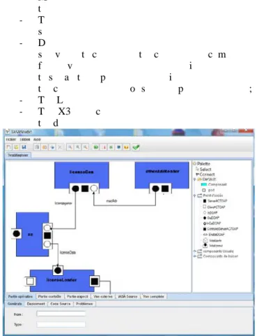
specification. IASAStudio has an organization that reflects the organization of the internal view of IASA components and allow the designer to easily specify the architecture. The GUI of the IDE includes the following views (Figure 6):
- Menu: To facilitate access to different features of the editor;
- Toolbar: For a quick start of the tool and the various services offered;
- Drawing area: The drawing area contains sub views to consider the composite component from various perspectives; thus it is possible to see all three parts of the internal view of the component model or see each part individually ; - The Library of components, ports, and connectors; - The X3ADL code area: the code corresponding to
the drawing is automatically generated.
Figure 4. The IASAStudio GUI
7.CONCLUSION
One of the main objectives of the IASA approach is to provide the models and the tools which have the ability to directly capture the architect mental model about a solution in the early steps of a software elaboration process. Usually, in the early step of a design process, boxes, lines and actions represent the main concepts used in the specification of a mental model. In this kind of specification, achieved far from any software mechanism, a software architect draws connections from one box to another, producing topologies which cannot be handled directly by current software architecture models and tools. This objective was reached in the IASA approach by the definition of the port model that allows the specification of a wide range of topologies far from any software mechanism. This aptitude is made possible by allowing the free manipulation of the elements defining a port during the specification of interconnections. The IASA approach has addressed other important concepts and notations that are well suited for the transformation of an informal specification to an X3ADL specification. This later is also transformed to achieve to an executable code in a
specific technology, through transformation rules as recommended by MDA.
Currently we are working on the improvement of the usability of the IASAStudio and the definition of transformation rules to support more target technologies for obtaining the executable code.
REFERENCES
[1] Aldrich, J., Chambers, C., Notkin, D., “ArchJava:
Connecting Software Architecture to Implementation”,In ICSE'02, Orlando, Florida, USA, 2002.
[2] Bennouar, D., T. Khammaci, A. Henni: “A new approach for component’s port modeling in software architecture”, Journal of Systems and Software, Vol. 83, Issue 8, pp. 1430-1442, Elsevier, 2010
[3] Bennouar, D., HENNI, A., “A Review of an Aspect Oriented Architecture Description Language”, The Meditaranen Journal of Computers and Networks, Vol 6, N° 1, pp 15-22, 2010, © 2010 SoftMotor Ltd., UK.
[4] Bennouar, D., “The Integrated Approach to Software
Architecture”, 2009, PhD thesis, ESI, Oued Smar,
Algies.
[5] Boer, R., van Vliet, H., “On the similarity between
requirements and architecture”, In Journal of Systems and Software 82 (3), 544–550, 2009.
[6] Bradbury, J., Cordy, R., Dingel, J., Elinger, M., “A
survey of self management in dynamic software architecture specifications”, In Proceedings of the ACM SIGSOFT International Workshop on Self-Managed Systems (WOSS’2004), ACM Press, 2004.
[7] Castroa, J., Lucenab, M., Silvac, C., Alencara, F., Santosa, E., Pimentela, J., “Changing attitudes towards the generation of architectural models”, The Journal of Systems and Software, doi:10.1016/j.jss.2011.05.047, 2011.
[8] Guessoum, D., “IASAStudio an IDE for specifying software architecture according to IASA approach” , Master Thesis, University of Blida, 2010, Internal Reports.
[9] Hassam, K., George, B., Régis, F., Sadou, S., “Using
the model transformation to facilitate the selection of software components”, IDM'2008.Mulhouse.
[10] Roh, S., Kim, K., Taewoong, J., “Architecture
modeling language based on UML2.0”, In APSEC’04 : Proceedings of the11th Asia-Pacific Software Engineering Conference, pages 663–669. IEEE Computer Society,2004.
[11] Ruscio, D., Malavolta, I., Muccini, H., Pelliccione, P., Pierantonio, A., “Developing next generation ADLs through MDE techniques”, ICSE ’10, 2010.
[12] Shaw, M., Clements, P., “The golden age of software
architecture: A comprehensive survey”, IEEE Software, 26(4):70–72, 2009, doi: 10.1109/MS.2009.83.
[13] Taylor, R. N., Medvidovic, N., Dashofy, E. M., “Software Architecture : Foundations, Theory, and Practice”,John Wiley & Sons, 2009.
[14] Weinreicha, R., Buchgeher, G., “Towards supporting
the software architecture life cycle”, The Journal of Systems and Software, doi:10.1016/j.jss.2011.05.036, 2011.