3D Tracking via Body Radio Reflections
Aw!e*
MASSACHUSErS INSTI11TEby
~ OF TECHNOLOGYby
JUL 15 2014
Zachary Kabelac
LIBRARIES
Submitted to the Department of Electrical Engineering and CoinpTe~ ~ ~Science in partial fulfillment of the requirements for the degree of Master of Engineering in Electrical Engineering and Computer Science
at the
MASSACHUSETTS INSTITUTE OF TECHNOLOGY
Mpy
2014
0 Massachusetts Institute of Technology 2014. All rights reserved.
Author ...
Signature redacted
Department of Electrical Engineering and Computer Science
May 2, 2014
Certified by ...
Signature redacted...
710
lina Katabi
Professor of Computer Science and Engineering
Thesis Supervisor
Signature redacted
Accepted by ...
....
Albert R. Meyer
Chairman, Master of Engineering Thesis Committee
3D Tracking via Body Radio Reflections
by
Zachary Kabelac
Submitted to the Department of Electrical Engineering and Computer Science
May 2, 2014
In partial fulfillment of the requirements for the Degree of
Master of Engineering in Electrical Engineering and Computer Science
Abstract
This thesis presents WiTrack, a system that tracks the 3D motion of a user from the radio signals reflected off her body. It works even if the person is occluded from the WiTrack device or in a different room. WiTrack does not require the user to carry any wireless device, yet its accuracy exceeds current RF localization systems, which require the user to hold a transceiver. Empirical measurements with a WiTrack prototype show that, on average, it localizes the center of a human body to within a median of 10 to 13 cm in the x and y dimensions, and 21 cm in the z dimension. It also provides coarse tracking of
body parts, identifying the direction of a pointing hand with a median of 11.20. WiTrack bridges a gap between RF-based localization systems which locate a user through walls and occlusions, and human-computer interaction systems like Kinect, which can track a user without instrumenting her body, but require the user to stay within the direct line of sight of the device.
Thesis Supervisor: Dina Katabi
Disclaimer
The work in this thesis was done in collaboration with another student, Fadel Adib. Most of the protocols in this thesis were developed during our discussions and brainstorming
sessions. We both share credit for the design and system architecture. My responsibility extended beyond the design to the realization of our off-the-shelf FMCW front-end and the empirical study of the device and its effectiveness.
Acknowledgements
I would like to thank Dina for allowing me the opportunity to pursue my research
interests and supporting me throughout. Having just met me, she gave me a unique opportunity to work on a project we were both very excited about. I'm very grateful for the guidance and knowledge you have given me and am excited to continue down this road for the upcoming few years.
I would also like to give a special thank you to Fadel for the time and effort you have
spent on many many sleepless nights. I've learned more from you than you can imagine and don't think I could have accomplished what we have with anyone else. And I'm sure there will be more success to come.
I am grateful to DOGS for their friendship and support throughout the process. I thank
Haitham, Jue, Deepak, Swarun, and Lixin for helping run countless experiments. And I'm grateful to Jouya, Omid, Ezz, and Rahul for their feedback and support during the stressful deadlines.
Lastly, I would like to genuinely thank my family, especially my parents, for their love and wisdom. I would not be in this position without you. Dad, you mentorship helped me to succeed and I couldn't have achieved this much without your help. This thesis is for you.
Contents
INTRODUCTION
13
1.1 3D Motion Tracking Through Walls
13
1.2 Evaluation of WiTrack
15
1.3 Contributions
17
RELATED WORK
19
2.1 Indoor Wireless Localization
19
2.2 FMCW Radar
20
2.3 Motion Tracking in User Interfaces
21
WITRACK OVERVIEW
23
TIME-OF-FLIGHT ESTIMATION
27
4.1 Obtaining Time-of-Flight Estimates
27
4.2 Addressing Static Multi-path
30
4.3 Addressing Dynamic Multi-path
33
4.4 Dealing with Noise
35
LOCALIZING IN 3D
37
BEYOND 3D TRACKING
41
6.1 Estimation of Pointing Angle
41
6.2 Fall Detection
44
IMPLEMENTATION
47
EVALUATION
51
8.1 Ground Truth
51
8.2 Device Setup
52
8.3 Human Subjects
52
PERFORMANCE RESULTS
53
9.1 Accuracy of 3D Tracking
53
9.2 Accuracy Versus Distance
55
9.3 Accuracy Versus Antenna Separation
57
9.4 Accuracy of Estimating Pointing Direction
60
9.5 Fall Detection
61
List of Figures
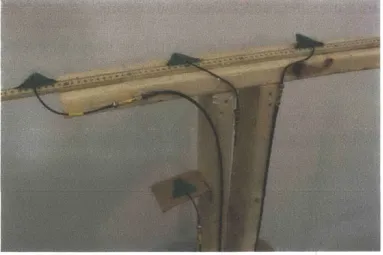
3-1 Antenna "T" Setup: shows WiTrack's directional antennas (dimension of each
antenna: 5cm x 5cm) arranged in a "T": the transmit antenna is placed at the crossing
point of the T, whereas the receive antennas are on the edges. 23
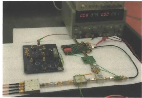
3-2 WiTrack Signal Generation: It shows the hardware built to generate the FMCW
signals. 24
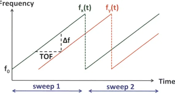
4-1 FMCW Operation: The Transmitted signal has a carrier frequency f,(t) that is
repeatedly swept in time. Because the received signal is time-shifted with respect to the transmitted signal, its carrier frequency fy(t) is frequency-shifted with respect to fQ(t). - 28
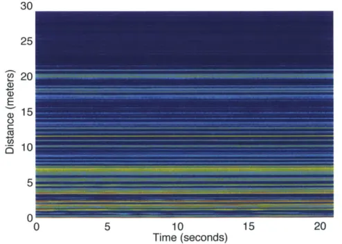
4-2 Spectrogram: WiTrack takes an FFT of the received signal in baseband over every sweep period to generate the spectrogram 31 4-3 After Background Subtraction: By subtracting out a given frame from the frame
that precedes it, WiTrack eliminates static multipath 33 4-4 Contour Tracking: WiTrack can address dynamic multipath by tracking the
bottom contour of Fig. 4-3 and then denoising the signal (red plot) to obtain a clean TOF
estimate. 35
5-1 Localizing in 2D: The TOF estimate from a receive antenna defines an ellipse
whose foci are the transmit antenna and the receive antenna. This figure shows that
WiTrack can uniquiely localize a person using the intersection of two ellipses. 37
5-2 3D Localization: This figure shows that in 3D, the problem translates into an
intersection of three ellipsoids. 38
6-1 Gestures: The figure shows a human moving then stopping and pointing with their
arm. The small bright regions around t = 18s and t = 21s correspond to the arm lifting
and dropping motions. 42
6-2 Fall Detection: WiTrack automatically detects falls by monitoring the absolute
value and the change in elevation. 45
7-1 Schematic of the Front End Design: WiTrack's front-end consists of an FMCW
signal generation component, and a receive chain that is connected to a USRP. 47
9-1 Performance of WiTrack's 3D Tracking: (a) and (b) show the CDF of the
location error for WiTrack in line-of-sight and through-wall scenarios respectively._ 54
9-2 Localization Accuracy Versus Distance to Device: (a)-(c) show the location
WiTrack. The median and 901h percentile errors increase as the distance from the device
to the person increases. 56
9-3 3D Localization Accuracy Versus Size of Device: (a)-(c) show the median and
90 th percentile location errors as a function of antenna seperation. Along all three
dimensions, a larger serparation leads to a decrease in the location error. 59 9-4 Orientation Accuracy: The CDF of the orientation accuracy shows that the
Chapter 1
INTRODUCTION
Recent years have witnessed a surge in motion tracking and localization systems. Multiple advances have been made both in terms of accuracy and robustness. In
particular, RF localization using WiFi and other communication devices has reached sub-meter accuracy and demonstrated its ability to deal with occlusions and non-line of sight scenarios [31, 18]. Yet these systems require the user to carry a wireless device in order to be localized. In contrast, systems like Kinect and depth imaging have revolutionized the field of human-computer interaction by enabling 3D motion tracking without
instrumenting the body of the user. However, Kinect and other imaging systems require a user to stay within the device's line-of-sight and cannot track her across rooms. We envision that if an RF system can perform 3D motion tracking without requiring the user to wear a radio, it will motivate the integration of such a technology in systems like Kinect to expand their reach beyond direct line of sight and enable through-wall human-computer interaction.
1.1 3D Motion Tracking Through Walls
Motivated by this vision, this document introduces WiTrack, a system that tracks the 3D motion of a user, using radio reflections that bounce off her body. It works through walls and occlusions, but does not require the user to carry any wireless device. WiTrack can also provide coarse tracking of a body part. In particular, the user may lift her hand and point at objects in the environment; the device detects the direction of the hand motion, enabling the user to identify objects of interest.
WiTrack has one antenna for transmission and three antennas for receiving. At a high level, WiTrack's motion tracking works as follows. The device transmits a radio signal and uses its reflections to estimate the time it takes the signal to travel from the
transmitting antenna to the reflecting object and back to each of the receiving antennas. WiTrack then uses its knowledge of the position of the antennas to create a geometric reference model, which maps the round trip delays observed by the receive antennas to a
3D position of the reflecting body.
Transforming this high-level idea into a practical system, however, requires addressing multiple challenges. First, measuring the time of flight is difficult since RF signals travel very fast, i.e. at the speed of light. To distinguish between two locations that are closer than one foot apart, one needs to measure differences in reflection time on the order of hundreds of picoseconds, which is quite challenging. To address this problem, we
leverage a technique called FMCW (frequency modulated carrier wave), which maps differences in time to shifts in the carrier frequency. Such frequency shifts are easy to
measure in radio systems by looking at the spectrum of the received signal.
A second challenge stems from multipath effects, which create errors in mapping the
delay of a reflection to the distance from the target. WiTrack has to deal with two types of multipath effects. Some multipath effects are due to the transmitted signal being reflected off walls and furniture. Others are caused by the signal first reflecting off the human body then reflecting off other objects. This is further complicated by the fact that in non-line-of-sight settings, the strongest signal is not the one directly bouncing off the human body. Rather, it is the signal that avoids the occluding object by bouncing off some sidewalls. WiTrack eliminates reflections from walls and furniture by noting that
their distance (and time of flight) does not change over time. Hence, they can be eliminated by subtracting consecutive frames of the signals. Reflections that involve a combination of a human and some static object are more complex and are addressed through filters that account for practical constraints on the continuity of human motion and its speed in indoor settings.
1.2 Evaluation of WiTrack
We have built a prototype of WiTrack and evaluated it empirically. Since off-the-shelf radios do not perform FMCW, we built an analog FMCW radio frontend, which operates as a daughterboard for the USRP software radio. In our evaluation, we use the VICON motion capture system [6] to report the ground truth location. VICON can achieve sub-centimeter accuracy but requires instrumenting the human body with infrared markers and positioning an array of infrared cameras on the ceiling. Since VICON cannot operate in non-line-of-sight, the human moves in the VICON room while our device is placed outside the room and tracks the motion across the wall. Our evaluation considers three applications; each of them uses the developed 3D tracking primitive in a different way. In the first application, we consider 3D tracking of human motion through a wall. The objective of such an application is to augment virtual reality and gaming systems to work in non-line-of-sight and across rooms. We compute the tracking error as the difference between the location reported by our device and the actual location of the body center as reported by VICON. Our results show that WiTrack localizes the center of the human body to within 10 to 13 cm in the x and y dimensions, and 21 cm in the z dimension. This high accuracy stems from WiTrack's ability to eliminate errors due to multipath and the
combined performance of FMCW and our geometric mapping algorithm. The results also show that even the 9 0th percentile of the measurements stays within one foot along the
x/y-axis and two feet along the z-axis.
In the second application, we consider elderly fall detection. Current solutions to this problem include inertial sensors, which old people tend to forget to wear [15], or cameras, which infringe on privacy, particularly in bedrooms and bathrooms [20]. In contrast, WiTrack does not require the user to wear any device and protects her privacy much better than a camera. However, simply looking at the change in elevation cannot allow us to distinguish a fall from sitting on the floor. Thus, WiTrack identifies a fall as a
fast change in the elevation that reaches the ground level. In a population of 11 users and over 133 experiments, WiTrack distinguishes a fall from standing, walking, sitting on a chair and sitting on the floor with an accuracy of 96.9% (the F-measure is 94.34%). In the third application, we consider a user who desires to control appliances by pointing
at them (e.g., the user can turn her monitor on or turn the lights off by simply pointing at these objects.) We consider a gesture in which the user lifts her arm, points at an
appliance, and drops her arm. By comparing the position of the arm over time, WiTrack can identify the pointing direction. Our prototype estimates the pointing direction with a median of 11.2 degrees and a 9 0th percentile of 37.9 degrees.
Our results also show that the prototype operates in real-time, and outputs the 3D location within 75 ms from the time the antennas receive the signal. Further, it operates at a fairly low power, transmitting only 0.75 milliwatts. However, our current prototype can track a single person, and requires the person to move to obtain an initial estimate of his
location.
1.3 Contributions
This thesis introduces the first device that can achieve centimeter-scale accuracy in
tracking the 3D motion of a human based on radio reflections off her body. It presents
new algorithms for eliminating errors due to multipath and performing accurate 3D
tracking, both of a whole body and a body part. The document also presents a prototype
implementation that includes a low power FMCW radio frontend and real-time
processing, delivering accurate 3D motion tracking to within a median of 10 to 20
centimeters.
Our results demonstrate that WiTrack can expand the space of human-computer
interfaces and enable interaction across walls, and occluded spaces. We believe that
WiTrack also expands the role that wireless computer networks may play in the future to
enable them to provide a variety of services: Communication is definitely a major
service, but other services may include motion tracking, through-wall human-computer
interaction, and a gesture based interface for controlling appliances and interacting with
the environment.
A video demonstrating the capabilities of WiTrack can be viewed at this link,
www.witrack.csail.mit.edu.'
The video can be found at the bottom of the website, www.witrack.csail.mit.edu.
Chapter 2
RELATED WORK
WiTrack is related to previous works in 3 important areas.
2.1 Indoor Wireless Localization
WiTrack builds on recent advances in RF-based localization [31, 18, 28, 11]. These
systems localize a wireless device using RSSI [11, 22], fine-grained-OFDM channel
information [25], antenna arrays [31, 18], or RFID backscatter [28, 27]. In contrast,
WiTrack localizes a human using body radio reflections.
Some past works in radio tomography use a network of tens or hundred sensors to track a
person even if she does not carry any wireless device [29, 30]. These works measure the
RSSI for each of the resulting n2 links between their sensors, and attribute the variation
of RSSI on a link to a human crossing that link. Other works on device-free localization
rely on RSSI fingerprints [32, 24], which are generated in a training phase by asking a
person to stand in different locations throughout the area of interest. In the testing phase,
they localize a person by mapping the resulting RSSI to the closest fingerprint. While
WiTrack shares the objective of tracking a person's motion without instrumenting her
body, it differs in both technology and accuracy. Specifically, WiTrack does not require
prior training and uses a few antennas that generate FMCW signals and measure the
time-of-flight of the signal reflections to infer location of a human. Its technique extends to
3D, and its 2D accuracy is more than 5x higher than the state of the art RSSI-based
systems [33, 24]. See through-wall & gesture recognition using WiFi: WiTrack is
motivated by recent research that used WiFi signals to detect users through walls and
identify some of their gestures [10, 21, 13]. Similar to these systems, WiTrack captures
and interprets radio reflections off a human body. WiTrack, however, differs from these
systems both in capability and technology. Specifically, these systems rely on the
Doppler shift of WiFi signals. Hence, they can distinguish only between getting closer or
getting further away, but cannot identify the location of the person.2 In contrast, WiTrack
measures the time of flight and, hence, can identify the exact location of a person. Among
these past systems, WiVi [10] focuses on tracking through dense walls such as concrete
by leveraging interference nulling to eliminate the wall's reflection. In contrast, WiTrack
focuses on accurate 3D motion tracking that operates through interior walls (which are
less dense than concrete)3, pinpointing the exact location of a user at any point in time.
2.2
FMCW Radar
WiTrack builds on past work on FMCW radar, including work that used FMCW for
see-through-wall that is targeted for the military [23, 12]. WiTrack however differs along
multiple dimensions. First, FMCW radios in past work were high-power and heavy
(needed to be mounted on a truck). Their tracking capabilities hinge on using large
antenna arrays that can achieve a narrow beam, which enables tracking a moving target.
In contrast, we present a light weight, low-power FMCW radio that complies with the
2 The gestures recognized by WiVi and WiSee are sequences of getting closer or getting further
away, which translate into positive and negative Doppler shifts. The work in [13] provides a distance estimate with an accuracy of about 30 meters.
3 To enable WiTrack to track through thicker walls such as concrete (as in WiVi), one may add a
filter to remove the wall's reflection.
FCC regulations for consumer devices. We are able to perform accurate tracking with a
low-power, relatively cheap FMCW prototype because of two innovations: first, a geometric localization algorithm that combines multiple measurements from different antenna locations and fits them within a geometric reference to pinpoint an accurate 3D location, and second, novel techniques that enable rejecting errors that are due to both static and dynamic multi-path in indoor environments. Further, WiTrack extends its techniques to tracking the motion of body parts, e.g., tracking a hand as it points in a particular direction.
2.3
Motion Tracking in User Interfaces
Finally, WiTrack is related to an emerging body of motion-tracking user interfaces. These include devices that the person needs to hold (such as the Nintendo Wii [4]) or wear (e.g., on-body sensors such as wristbands [1, 14, 17]). They also include vision and infrared-based systems, like Xbox Kinect [8] and Leap Motion [3], which can track a person's movement without requiring her to hold or wear any transmitter or receiver but require the user to maintain a line-of-sight path to their sensors. Similar to these systems, WiTrack enables more natural human-computer interaction. However, in comparison to these systems, WiTrack does not require the user to hold/wear any device or to maintain a line-of-sight path to its sensors; it can track a user and her gestures in non-line-of-sight and across different rooms.
Chapter 3
WITRACK OVERVIEW
WiTrack is a wireless system that performs 3D motion tracking in both line-of-sight and
through wall scenarios. It can also provide coarse tracking of body parts, like an arm
movement. WiTrack uses multiple directional antennas: one antenna is used for
transmitting, and three antennas for receiving. In its default setup, the antennas are
arranged in a "T" shape, as shown in Fig. 3-1. In its current version WiTrack tracks one
moving body at any time. Other people may be around but should be either behind the
4
antenna beam or they should be approximately static.
Figure 3-1: Antenna "T" Setup: shows WiTrack's directional antennas (dimension of each antenna: 5cm x 5cm) arranged in a "T": the transmit antenna is placed at the
crossing point of the T, whereas the receive antennas are on the edges.
4 Small moving objects, which do not have significant reflections (e.g., a plastic fan), create some noise but do not prevent WiTrack's 3D tracking.
Figure 3-2: WiTrack Signal Generation: It shows the hardware built to generate the FMCW signals.
WiTrack operates by transmitting an RF signal and capturing its reflections off a human body. It tracks the motion by processing the signals from its received antennas using the following three steps:
1. Time-of-Flight (TOF) Estimation: WiTrack first measures the time it takes for its signal to travel from its transmit antenna to the reflecting body, and then back to each of its receive antennas. We call this time the TOF (time-of-flight). WiTrack obtains an initial measurement of the TOF using FMCW transmission technique; it then cleans this estimate to eliminate multipath effects and abrupt jumps due to noise.
2.3D Localization: Once it obtains the TOF as perceived from each of its receiving antennas, WiTrack leverages the geometric placement of its antennas to localize the moving body in 3D.
3. Fall Detection and Pointing: WiTrack builds on the 3D localization primitive to
enable new functionalities. Specifically, WiTrack can detect a fall by monitoring fast changes in the elevation of a human and the final elevation after the change. WiTrack can also differentiate an arm motion from a whole body motion; it can track the motion of raising one's arm, localize the initial and final position of the arm, and determine the direction in which the arm is pointing.
Chapter 4
TIME-OF-FLIGHT ESTIMATION
The first step for WiTrack is to measure the TOF from its transmit antenna to each of its receive antennas and clean this estimate from the effect of multi-path.
4.1 Obtaining Time-of-Flight Estimates
A straightforward approach for estimating the time of flight is to transmit a very short
pulse and measure the delay between the transmitted pulse and its received echo. Such a design requires sampling the signal at sub-nanosecond intervals - i.e. it requires high-speed analog-to-digital converters (ADCs) that operate at multi-GS/s. Such ADCs are high power, expensive, and have low bit resolution, making this approach unattractive in practice.
Instead, WiTrack measures the TOF by leveraging a technique called Frequency-Modulated Carrier Waves (FMCW). We explain FMCW at a high level, and refer the reader to [19] for a more detailed explanation. FMCW transmits a narrowband signal (e.g., a few KHz) whose carrier frequency changes linearly with time. To identify the distance from a reflector, FMWC compares the carrier frequency of the reflected signal to that of the transmitted signal. Since the carrier frequency is changing linearly in time, delays in the reflected signals translate into frequency shifts in comparison to the transmitted wave. Therefore, by comparing the frequency difference between the
incurred, which corresponds to the TOF of that signal.
Frequency
f(t)
f(t)
TOF
U
sweep 1
sweep 2
+Time
Figure 4-1: FMCW Operation: The Transmitted signal has a carrier frequency f,(t) that is repeatedly swept in time. Because the received signal is time-shifted with respect to the transmitted signal, its carrier frequency fy(t) is frequency-shifted with respect to f(t). Fig. 4-t illustrates this concept. The green line is the carrier frequency of the transmitted
signal, which sweeps linearly with time. The red line is the carrier frequency of the reflected signal as a function of time. The time shift between the two is the time-of-flight
(TOF) for that reflector. The frequency shift Af between the transmitted and received signals is a function of both the slope of the sweep and the TOF, i.e.:
TOF =
slope
(4.1)Though the above description is for a single reflector, it can be easily generalized to an environment with many reflectors. In this case, the transmitted signal would still consist
of a single carrier wave that is linearly swept in time. However, because wireless
reflections add up linearly over the medium, the received signal is a linear combination of
multiple reflections, each of them shifted by some 4f that corresponds to its own TOF.
Hence one can extract all of these TOFs by taking a Fourier Transform (i.e. an FFT) of
the received baseband signal.'
In comparison to transmitting a very short pulse and measuring its sub-nanosecond delay
in the time domain, FMCW does not require high speed ADCs because at any point in
time, the received baseband signal is narrowband.
FMCW Resolution: It is important to note that the resolution of an FMCW system is a
function of the total bandwidth that the carrier frequency sweeps [19]. The resolution is
defined by the ability to distinguish between two nearby locations, which depends on the
ability to distinguish their TOFs, which itself depends on the resolution in distinguishing
frequency shifts Af. The resolution of identifying frequency shifts is equal to the size of
one bin of the FFT. The FFT is typically taken over a period of one sweep of the carrier
frequency (denoted by Tsweep) and hence the size of one FFT bin is l/Tsweep. Since the
minimum measurable frequency shift is Afmin = l/Tsweep, the minimum measurable
change in location is:
T___F Afmi
Resolution = C * '"'" = C * sl (4.2)
2 2*slope
where C is the speed of light and the factor 2 accounts for the fact that the reflected signal
s The baseband signal is the received signal after mixing it by the transmitted carrier. The mixing shifts the spectrum of the received signal by the transmitted carrier frequency.
traverses the path back and forth.
The slope, however, is equal to the total swept bandwidth B divided by the sweep time Tsweep. Hence, after substituting for the slope in the above equation we get:
C
Resolution = - (4.3)
2*B
Since C is very large, obtaining high resolution requires a large B, i.e., the system has to
take a narrowband signal and sweep its carrier frequency across a wide bandwidth of
multiple GHz.
In our design we chose the following parameter for our FMCW. We have built an FMCW
system that sweeps a total bandwidth of 1.69 GHz from 5.56 GHz to 7.25 GHz, and
transmits at 0.75 milliwatt. The choice of this bandwidth has been dictated by the FCC
regulations for civilian use of spectrum [9]. Specifically, it is the largest contiguous
bandwidth below 10 GHz, which is available for civilian use at low power.
Based on Eq. 4.3, our sweep bandwidth allows us to obtain a distance resolution of 8.8
cm. Hence the average error in mapping TOF to distance in ID is about 4.4 cm. Note that
the above derivation neglects the impact of noise, and hence provides a lower bound on
the achievable resolution. In practice, the system's resolution is affected by the noise
level. It also depends on the geometric model that maps TOFs to 3D locations.
4.2 Addressing Static Multi-path
The next step in WiTrack's operation is to distinguish a human's reflections from
reflections off other objects in the environment, like furniture and walls. Recall from the
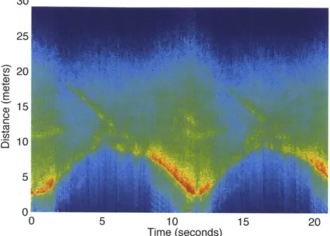
previous section that every reflector in the environment contributes a component to the overall received signal, and that component has a frequency shift that is linearly related to the time-of-flight of the reflection based on Eq. 4.1. Typically, reflections from walls and furniture are much stronger than reflections from a human, especially if the human is behind a wall. Unless these reflections are removed, they would mask the signal coming from the human and prevent sensing her motion. This behavior is called the "Flash Effect". To remove reflections from all of these static objects (walls, furniture), we leverage the fact that since these reflectors are static, their distance to the WiTrack device does not change over time, and therefore their induced frequency shift stays constant over time. 30 25 '20 a> E S15 C.1 C i510 5 0" 0 5 10 15 20 Time (seconds)
Figure 4-2: Spectrogram: WiTrack takes an FFT of the received signal in baseband over every sweep period to generate the spectrogram
Fig. 4-2 plots the spectrogram of the received signal as a function of time, for one of the receive antennas of WiTrack. In particular, we take the FFT of the received signal every sweep window, and compute the power in each frequency as a function of time. Note that
there is a linear relation between frequency shifts and the traveled distances as follows:
distance = C * TOF = C * Af(4.4)
slope
Thus, instead of plotting the power in each frequency as a function of time, we can use the above equation to plot the power reflected from each distance as a function of time, as shown in Fig. 4-2. The color code of the plot corresponds to a heat map of the power in the reflected signal. Strong reflectors are indicated by red and orange colors, weaker reflectors are indicated by yellow and green, and the absence of a reflector is indicated by blue at the corresponding frequency. The figure indicates the presence of very strong static reflectors in the environment. Specifically, it has many horizontal stripes; each of these stripes signifies the presence of a reflector at the corresponding round-trip distance. Because these stripes are horizontal, their corresponding reflectors are stationary over time. Hence, we eliminate the power from these static reflectors by simply subtracting the output of the FFT in a given sweep from the FFT of the signal in the previous sweep. This process is called background subtraction because it eliminates all the static reflectors in the background.
30 25 ~20 >0 E C 15 0 0 5 10 15 20 Time (seconds)
Figure 4-3: After Background Subtraction: By subtracting out a given frame from the frame that precedes it, WiTrack eliminates static multipath
Fig. 4-3 is the result of applying background subtraction to Fig. 4-2. The figure shows that all static reflectors corresponding to the horizontal lines have been eliminated. This makes it easier to see the much weaker reflections from a moving human. Specifically, we see that the distance of the dominant reflector (the red color signal) is varying with time, indicating that the reflector is moving.
4.3 Addressing Dynamic Multi-path
By eliminating all reflections from static objects, WiTrack is left only with reflections
from a moving human (see Fig. 4-3). These reflections include both signals that bounce off the human body to the receive antennas, and those that bounce off the human then bounce off other objects in the environment before reaching WiTrack's antennas. We
refer to these indirect reflections as dynamic multi-path. It is quite possible that a human reflection that arrives along an indirect path, bouncing off a sidewall, is stronger than her direct reflection, which could be severely attenuated after traversing a wall, because the former might be able to avoid occlusion.
Our idea for eliminating dynamic multi-path is based on the observation that, at any point in time, the direct signal reflected from the human to our device has travelled a shorter path than indirect reflections. Because distance is directly related to TOF, and hence to frequency, this means that the direct signal reflected from the human would result in the smallest frequency shift among all strong reflectors after background subtraction.
We can track the reflection that traveled the shortest path by tracing the bottom contour of all strong reflectors in Fig. 4-3. The bottom contour can be defined as the closest local maximum to our device. To determine the first local maximum that is caused by human motion, we must be able to distinguish it from a local maximum due to a noise peak. We achieve this distinguishability by averaging the spectrogram across multiple sweeps. In our implementation, we average over five consecutive sweeps, which together span a duration of 12.5 ms. For all practical purposes, a human can be considered as static over this time duration; therefore, the spectrogram would be consistent over this duration. Averaging allows us to boost the power of a reflection from a human while diluting the peaks that are due to noise. This is because the human reflections are consistent and hence add up coherently, whereas the noise is random and hence adds up incoherently. After averaging, we can determine the first local maximum that is substantially above the noise floor and declare it as the direct path to the moving human.
30 Contour Denoised Contour 25 -20 -2 E C C o10 5 0 0 5 10 15 20
Time (in seconds)
Figure 4-4: Contour Tracking: WiTrack can address dynamic multipath by tracking the bottom contour of Fig. 4-3 and then denoising the signal (red plot) to obtain a clean TOF
estimate.
The blue plot in Fig. 4-4 shows the output of WiTrack's contour tracking of the signal in Fig. 4-3. In practice, this approach has proved to be more robust than tracking the
dominant frequency in each sweep of the spectrogram. This is because, unlike the
contour which tracks the closest path between a human body and WiTrack's antennas, the point of maximum reflection may abruptly shift due to different indirect paths in the environment or even randomness in the movement of different parts of the human body as a person performs different activities.
4.4 Dealing with Noise
After obtaining the bottom contour of the spectrogram of the signal from each receive antenna, WiTrack leverages common knowledge about human motion to mitigate the
effect of noise and improve its tracking accuracy. Specifically, by performing the following optimizations, we obtain the red plot in Fig. 4-4:
Outlier Rejection: WiTrack rejects impractical jumps in distance estimates that
correspond to unnatural human motion over a very short period of time. For example, in Fig. 4-4, the distance from the reflector (the blue line) repeatedly jumps by more than 5
meters over a span of few milliseconds. Such changes in distance are not possible over such small intervals of time, and hence WiTrack rejects such outliers.
Interpolation: WiTrack uses its tracking history to localize a person when she stops
moving. In particular, if a person walks around in a room then sits on a chair and remains static, the background-subtracted signal would not register any strong reflector. In such scenarios, we assume that the person is still in the same position and interpolate the latest location estimate throughout the period during which we do not observe any motion, enabling us to track the location of a subject even after she stops moving.
Filtering: Because human motion is continuous, the variation in a reflector's distance to
each receive antenna should stay smooth over time. Thus, WiTrack uses a Kalman Filter to smooth the distance estimates.
Chapter
5
LOCALIZING IN 3D
After contour tracking and de-noising of the estimate, WiTrack obtains a clean estimate of the distance travelled by the signal from the transmit antenna to the human reflector, and back to one of the receive antennas. Let us call this estimate the round trip distance. At any time, there are three such round trip distances that correspond to the three receive antennas. The goal of this section is to use these three estimates to identify the 3D position of the human, for each time instance.
To do so, WiTrack leverages its knowledge of the placement of the antennas. Recall that the antennas are placed in a T, as in Fig. 3-1, where the y-axis is a horizontal line
orthogonal to the plane of the T and the z-axis is along its vertical line. WiTrack uses this reference frame to track the 3D location of a moving target.
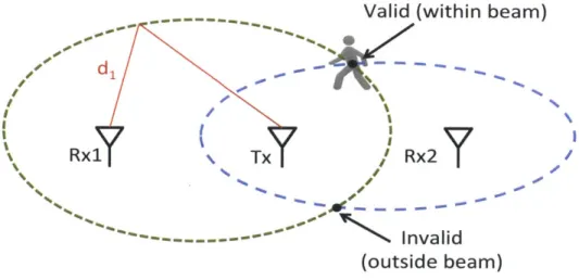
Valid (within beam)
Rx1 Tx Rx2
IA I
- - - Invalid
(outside beam)
Figure 5-1: Localizing in 2D: The TOF estimate from a receive antenna defines an ellipse whose foci are the transmit antenna and the receive antenna. This figure shows
Let us focus on identifying the location at a particular time ti. Also for clarity, let us first assume that we would like to localize the person in the 2D plane defined by the x and y axes. Consider the transmit antenna and the first receive antenna. WiTrack knows the round trip distance from the transmit antenna to the person and back to the first receive antenna. The region of feasible 2D locations for the target need to satisfy this constraint; hence, they fall on the periphery of an ellipse, whose foci are collocated with the Tx and Rxl antennas and its major axis is equal to the round trip distance. Now consider the second receive antenna. WiTrack knows the round trip distance from the Tx to the person and back to Rx2. Similarly, the feasible solutions to this constraint in 2D are on the periphery of another ellipse whose foci are collocated with the Tx and Rx2 antennas and its major axis is equal to the round trip distance to Rx2. Since the correct location is on both ellipses, it is one of the intersection points, as shown in Fig. 5-1. In fact, since our antennas are directional, only one of the two intersection points is feasible, which is the one that yields a location in the direction of the antennas beams.
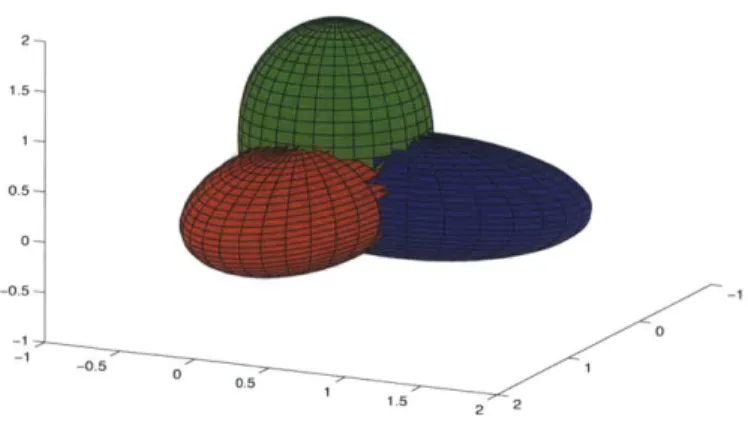
2- 1.5- 0.5- 0- -0.5--0 -0.5 1 1 1.5 2 2
Figure 5-2: 3D Localization: This figure shows that in 3D, the problem translates into an intersection of three ellipsoids.
It is straightforward to generalize the argument to localizing in 3D. Specifically, in a 3D space, the round-trip distance defines an ellipsoid whose two foci are the transmit antenna and one of the receive antennas. In this setting, the intersection of two ellipsoids would define an arc in the 3D space, and hence is insufficient to pinpoint the 3D location of a person. However, by adding a third directional antenna, we obtain a unique solution in
3D that is within the beam of all the directional antennas as shown in Fig. 5-2. Therefore, our algorithm can localize a person in 3D by using three directional receive antennas. Finally we note two points:
e The T-shape placement for the antennas is chosen because we assume the user
wants to localize motion behind a wall, in which case all the antennas would have to be arranged in one plane facing the wall. We place one antenna below to help determine elevation, while the others are on the same level.
* b) While the minimum number of Rx antennas necessary to resolve a 3D location is three, adding more antennas would result in more constraints. This would allow us to over-constrain the solution and hence add extra robustness to noise.
Chapter 6
BEYOND 3D TRACKING
In this section, we build on WiTrack's 3D localization primitive to enable two additional capabilities: estimating a pointing direction from the corresponding arm movement, and detecting a fall.
6.1 Estimation of Pointing Angle
We explain how WiTrack provides coarse estimation of body part motion. We consider the following motion: the user starts from a state where her arm is rested next to her body. She raises the arm in a direction of her choice with the intention of pointing toward a device or appliance, and then drops her hand to the first position. The user may move around and at a random time perform the pointing gesture. We require, however, that the user be standing (i.e., not walking) when performing the pointing gesture. The goal is to detect the pointing direction.
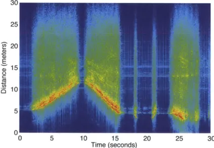
To track such a pointing gesture, WiTrack needs to distinguish between the movement of the entire body and the motion of an arm. To achieve this goal, we leverage the fact that the reflection surface of an arm is much smaller than the reflection surface of an entire human body. We estimate the size of the reflection surface from the spectrogram of the received signal at each of the antennas. Fig. 6-1 illustrates the difference between the spectrogram of a whole body motion and that of an arm pointing, as captured by one of WiTrack's receiving antennas. In the figure the human was moving then stopped and
performed the pointing gesture. The two bright spots around t = 18s and t = 21s refer to the arm being lifted and dropped respectively. The figure shows that the signal variance along the vertical axis is significantly larger when the reflector is the entire human body than when it is just an arm motion (note the bright yellow as opposed to the cyan color).
If the reflector is large, its parts have slightly different positions from each other; hence,
at any point in time the variance of its reflection along the y-axis is larger than that of an arm movement. WiTrack uses this spatial variance to detect body part motion from a whole body motion.
E, 5) 30 25 20 15 10 0 5 10 15 20 25 30 Time (seconds)
Figure 6- 1: Gestures: The figure shows a human moving then stopping and pointing with their arm. The small bright regions around t = 18s and t = 21s correspond to the arm
lifting and dropping motions.
Once we detect it is a body part, WiTrack tries to estimate the direction of the motion to identify the pointing direction, which involves the following steps:
gesture. Fig. 6-1 shows how WiTrack segments the round trip distance spectrogram
obtained from each receive antenna. In our pointing experiments, we ask the user to
remain static for a second before performing the pointing gesture. Thus, we are able to
detect the start of a pointing gesture since it is always preceded by a period of absence of
motion. Similarly, after a person raises her arm in a pointing direction, we ask her to wait
for a second before resting her arm back to its initial position. Because WiTrack performs
a frequency sweep every 2.5 ms, we can easily distinguish the silence at the start and end
of a gesture.
Denoising: As is the case for a whole body motion, the contour of the segmented
spectrogram is denoised and interpolated (see 4.4) to obtain a clean estimate of the
round trip distance of the arm motion as a function of time, for each receive antenna.
Determining the Pointing direction: We perform robust regression on the location
estimates of the moving hand, and we use the start and end points of the regression from
all of the antennas to solve for the initial and final position of the hand. WiTrack
estimates the direction of pointing as the direction from the initial state to the final
extended state of the hand. Since the user drops her hand after pointing, WiTrack repeats
the above steps for this drop motion obtaining a second estimate of the pointing direction.
Then, WiTrack estimates the pointing direction as the middle direction between the two.'
Being able to leverage the approximate mirroring effect between the arm lifting and arm
dropping motions adds significant robustness to the estimation of the pointing angle.
6 By zooming on Fig. 5, the reader can see how the arm lifting and dropping motions approximately mirror each other's tilt.
We envision that an application of the estimation of pointing direction can be to enable a
user to control household appliances by simply pointing at them. Given a list of
instrumented devices and their locations, WiTrack would track the user's hand motion, determine the direction in which she points, and command the device to change its mode
(e.g., turn on or off the lights, or control our blinds).
Finally, to demonstrate the pointing gesture within the context of an application, we
created a setup where the user can control the operation mode of a device or appliance by
pointing at it. Based on the current 3D position of the user and the direction of her hand,
WiTrack automatically identifies the desired appliance from a small set of appliances that
we instrumented (lamp, computer screen, automatic shades). Our instrumentation is a
basic mode change (turn on or turn off). WiTrack issues a command via Insteon home
drivers [2] to control the devices. We envision that this setup can evolve to support a
larger set of functionalities and can be integrated within home automation systems [16].
6.2 Fall Detection
Our objective is to automatically distinguish a fall from other activities including sitting
on the ground, sitting a chair and walking. To do so, we build on WiTrack's elevation
tracking along the z dimension. Note that simply checking the person's elevation is not
sufficient to distinguish falls from sitting on the floor. To detect a fall, WiTrack requires
two conditions to be met: First, the person's elevation along the z-axis must change
significantly, by more than one third of its value, and the final value for her elevation
must be close to the ground level. The second condition is the change in elevation has to
occur within a very short period to reflect that people fall quicker than they sit.
2 1.5 E C C 0 0.5 Walk 1w Sit on Chair Sit on Ground -0 Fall 0 5 10 15 20 25 30 Time (in seconds)
Figure 6-2: Fall Detection: WiTrack automatically detects falls by monitoring the absolute value and the change in elevation.
Fig. 6-2 plots WiTrack's estimate of the elevation along the z dimension for four
activities: a person walking, sitting on a chair, sitting on the ground, and (simulated)
falling on the ground.! The figure confirms that walking and sitting on a chair can be
identified from falling and sitting on the floor based on elevation because the final
elevation is far from z =0. However, to distinguish a fall on the ground from a sitting on
the ground, one has to exploit that during a fall the person changes her elevation faster
than when she voluntarily sits on the floor.
7The fall was performed in a padded room as detailed in 8.5.
Chapter 7
IMPLEMENTATION
FMCW Radio Front-End Hardware: We have built an FMCW front-end that operates as a daughterboard for the USRP software radio [5]. Below, we describe our design, which is illustrated in the schematic of Fig. 7-1.
Signal Generation
Tx
VCO BandPass Filter Amp
Frequency Hg~s Divider USPHighPass Filter LNA Rx1 Phase Frequency ----Detector - ---Digital ~ ' Rxn Synthesizer
Figure 7-1: Schematic of the Front End Design: WiTrack's front-end consists of an FMCW signal generation component, and a receive chain that is connected to a USRP. The first step of our front-end design is the generation of an FMCW signal, which consists of a narrowband signal whose carrier frequency is linearly swept over a large bandwidth. This signal can be obtained by using a voltage-controlled oscillator (VCO). Because the output frequency of a VCO is a linear function of its input voltage, we can generate our desired frequency sweep by feeding a voltage sweep as an input to the VCO. However, small errors in the input voltage can create large nonlinearities in the output sweep.
To obtain a highly linear sweep, we use a feedback mechanism. Specifically, we use a phase frequency detector to compare the output frequency of the VCO with a highly accurate reference signal, and use the offset between the two to control the VCO. Note that even though the reference signal needs to be highly accurate, it does not need to span the same bandwidth as our desired output signal. In particular, rather than directly
comparing the output of the VCO to the reference signal, we first use a frequency divider. This allows us to use a reference signal that sweeps from 136.5-181.25 MHz to generate an FMCW signal that sweeps from 5.46-7.25 GHz. This FMCW signal is transmitted over the air using WA5VJB directional antennas [7] after filtering and amplification. At the receive chain, the transmitted signal is captured using WA5VJB directional antennas and passed through a low-noise amplifier and a high-pass filter to improve its
SNR. Recall from 3 that an FMCW receiver determines the TOF by measuring the frequency offset between the transmitted and the received signal. This offset can be obtained by down converting (mixing) the received signal with the transmitted signal. The output of the mixer is then fed to the LFRX-LF daughterboard on USRP2, which samples it at 1 MHz and passes the digitized samples to the UHD driver.
Real-time Software Processing: The implemented prototype performs real-time 3D motion tracking as described in 4, 5 and 6. Tracking is implemented directly in the
UHD driver of the USRP software radio. The signal from each receiving antenna is
transformed to the Frequency domain using an FFT whose size matches the FMCW sweep period of 2.5ms. To improve resilience to noise, every five consecutive sweeps are averaged creating one FFT frame. Background subtraction is performed by subtracting the averaged FFT frame from the frame that precedes it. The spectrogram is processed for
contour tracking by identifying for each time instance the smallest local frequency maximum that is significantly higher than the noise level. Outlier rejection is performed
by declaring that the contour should not jump significantly between two successive FFT
frames (because a person cannot move much in 12.5ms). The output is smoothed with a Kalman filter.
To locate a person, instead of solving a system of ellipsoid equations in real-time, we leverage that the location of the antennas does not change and is known a priori. Thus, before running our experiments, we use MATLAB's symbolic library to find a symbolic representation of the solutions (x, y, Z) as a function of symbolic TOF to each of the receiving antennas. This means that the ellipsoid equations need to be solved only once (for any fixed antenna positioning), independent of the location of the tracked person. After it obtains the 3D location of a person, WiTrack uses python's matplotlib library to output this location in real-time.
Software processing has a total delay less than 75 ms between when the signal is received an a corresponding 3D location is output.
Chapter 8
EVALUATION
We empirically evaluate the performance of the WiTrack prototype by conducting experiments in our lab building with 11 human users.
8.1 Ground Truth
We determine WiTrack's localization accuracy by testing it against the VICON motion capture system. The VICON is a multi-hundred-thousand dollar system used in
filmmaking and video game development to track the human motion and map it to a 3D character animation model. It uses calibrated infrared cameras and records motion by instrumenting the tracked body with infrared-reflective markers. The VICON system has a sub-centimeter accuracy and hence we use it to determine the ground truth location. To track a moving person with the VICON, she is asked to wear a jacket and a hat, which are instrumented with eight infrared markers. To track a subject's hand, she is asked to wear a glove that is also instrumented with six markers. The VICON tracks the infrared markers on the subject's body and fits them to a 3D human model to identify the subject's location.
The VICON system has a built-in capability that can track the center of any object using the infrared-reflective markers that are placed on that object. This allows us to determine the center position of a human subject who is wearing the instrumented jacket and hat. WiTrack however computes the 3D location of the body surface where the signal reflects.
In order to compare WiTrack's measurements to those obtained by the VICON, we need to have an estimate of the depth of the center with respect to the body surface. Thus, we use the VICON to run offline measurements with the person standing and having infrared markers around her body at the same height as the WiTrack transmit antenna (about the waist). We use the VICON to measure the average depth of the center from surface for each person. To compare the 3D location computed by the two systems, we first
compensate for the average distance between the center and surface for that person and then take the Euclidean distance.
8.2 Device Setup
WiTrack is placed behind the wall of the VICON room. The device uses one transmit antenna and three receive antennas. The transmit antenna and two receive antennas are lined up parallel to the wall, and a third receive antenna is placed below the transmit antenna. The distance between the transmit antenna and each receive antenna is lm, unless otherwise noted.
8.3 Human Subjects
The experiments are performed with eleven human subjects: two females and nine males. The subjects are of different heights and builds, and span an age range of 22 to 56 years. In each experiment, the subject is asked to move at will in the VICON room; he/she is tracked using both the VICON system and WiTrack. Note that WiTrack tracks the subject through the wall, from an adjacent room, while the VICON has to be within direct line of sight from the subject.
Chapter 9
PERFORMANCE RESULTS
9.1 Accuracy of 3D Tracking
We first focus on the developed 3D tracking primitive and evaluate its accuracy across all three dimensions.
We run 100 experiments, each lasting for 1 minute, during which a human subject moves at will in the VICON room. The VICON room has no windows. It has 6-inch hollow walls supported by steel frames with sheet rock on top, which is a standard setup for office buildings. The WiTrack prototype is placed outside the room with all transmit and receive antennas facing one of the walls of the VICON room. Recall that WiTrack's antennas are directional; hence, this setting means that the radio beam is directed toward the wall of the VICON room. In each experiment, we ask the subject to wear the jacket and hat that were instrumented with VICON markers and move inside the VICON-instrumented room. The subject's location is tracked by the VICON system and WiTrack. We note that the VICON IR cameras are set to accurately track the target only when she moves in a 6 x 5 m2 area in the room. Their accuracy degrades outside that area. Since
VICON provides the ground truth in our experiment, we ask the target to stay within the 6 x 5 m2 area where the IR cameras are focused. This area is about 2.5m away from the
wall. Thus, the minimum separation between WiTrack and the human subject in these experiments is 3 m and the maximum separation is about 9 m.
We perform a total of 100 experiments for this evaluation, each lasting for one minute. Since each FMCW sweep lasts for 2.5ms and we average 5 sweeps to obtain for each TOF measurement, we collect a total of about 480,000 location readings from these 100 experiments.
To show that WiTrack works correctly both in line of sight and through a wall, we repeat the above 100 experiments with one modification, namely we move the WiTrack device inside the room and set it next to the wall from the inside.
U) C 0.8 EE 0.8 0.6 0.6 E .4 0.4 8 0.a)En 0.2 x dimension -0.2 dimension y dimension u.ydmens;o - -zdiesion zL dimension - dieso 0 0 20 z dimension 0 0 20 40 60 80 100
40 60 80 100 Location Error (in centimeters)
Location Error (in centimeters)
(a) CDF in line-of-sight (b) CDF in non-line-of-sight
Figure 9-1: Performance of WiTrack's 3D Tracking: (a) and (b) show the CDF of the location error for WiTrack in line-of-sight and through-wall scenarios respectively. Fig. 9-1(a) and Fig. 9-1(b) plot the CDFs of the location error along the x, y, and z
coordinates. The figure reveals the following findings:
* WiTrack's median location error for the line-of-sight experiments is 9.9 cm, 8.6 cm, and 17.7 cm along the x, y, and z dimensions respectively. In comparison, the median location error in the through-wall experiments is 13.1 cm, 10.25 cm, and
21.0 cm along the x, y, and z dimensions. As expected the location accuracy in line-of-sight is higher than when the device is behind a wall due to the extra
attenuation and the reduced SNR. In both cases, however, the median error is fairly small. This is due to the use of an FMCW radio, which ensures a highly
accurate TOF estimate, and the ability to prevent errors due to multipath and noise, allowing the system to stay accurate as it moves from TOF to a 3D location estimate of the human body.
* Interestingly, the accuracy in the y dimension is better than the accuracy in the x dimension. This difference is because the x and y dimensions are not equal from the perspective of WiTrack's antennas. Recall that in the xy-plane, WiTrack's antennas are all along the x-axis. As a result, the two ellipses in the xy-plane, shown in Fig. 9-1, both have their major radius along x and minor radius along y. Hence, the same error in TOF produces a bigger component when projected along the x axis than along the y axis.
* The accuracy along the z-dimension is worse than the accuracy along the x and y dimensions. This is the result of the human body being larger along the z
dimension than along x or y.
9.2 Accuracy Versus Distance
We are interested in evaluating WiTrack's accuracy as the person gets further away from the device. Thus, we repeat the above through-wall experiments. As mentioned above,
VICON requires the human to move in a certain space that is in line of sight of the IR
cameras. Thus, to increase the distance from WiTrack to the human we move WiTrack away in the hallway next to the VICON room. Again, we collect 100 experiments, each spanning one minute for a total of 480,000 location measurements.
50 Median CD 90th Percentile E 40 30 0 w 20 C 1 0 C-,~a100
ii
iii ll
1 2 3 4 5 6 7 8 9 10 11 Distance from transmitter (in meters)(a) Accuracy in x-dimension
30 Median 90th Percentile E 25 CD 8 20 15 2 10 0 0 1 2 3 4 5 6 7 8 9 10 11 Distance from transmitter (in meters)
(b) Accuracy in y-dimension a 80 Median 90th Percentile --E 70 60 50 240 30 0 20 as 10 .90 1 2 3 4 5 6 7 8 9 10 11 Distance from transmitter (in meters)
(c) Accuracy in z-dimension
Figure 9-2: Localization Accuracy Versus Distance to Device: (a)-(c) show the location error along the x, y, and z dimensions as a function of how far the subject is
from WiTrack. The median and 90th percentile errors increase as the distance from the device to the person increases.