Influence of deposition parameters on mechanical properties
of sputter-deposited Cr
2O
3thin films
P. Hones and F. Le´vy
EPFL-Institut de physique applique´e, Ecole Polytechnique Fe´de´rale de Lausanne, CH-1015 Lausanne, Switzerland
N.X. Randall
CSEM Instruments, Jaquet-Droz 1, CH-2007 Neuchaˆtel, Switzerland
Among the oxides, Cr2O3exhibits the highest hardness value and a low coefficient of friction. These properties make chromium oxide an excellent coating material for tribological applications. Cr2O3thin films were deposited by radio-frequency reactive magnetron sputtering at substrate temperature in the range 363–593 K. The hardness and elastic modulus of the films were measured by two complementary
nanoindentation techniques to investigate the influences of the substrate temperature and the oxygen content in the sputtering gas. While the continuous stiffness data method provides information throughout the whole film thickness, nanoindentation combined with scanning force microscopy of the residual imprints allows visualiza-tion of pileup, cracking, and delaminavisualiza-tion from the substrate. Hardness values up to 32 GPa were obtained for substrate temperatures exceeding 500 K and oxygen contents between 15% and 25% of the total gas pressure. The films, obtained with these
deposition conditions, showed good adhesion to silicon substrates.
I. INTRODUCTION
It has been established that Cr2O3is among the hardest oxides both in the mineralogical (8.5 Mohs) and in the microhardness scales (29.5 GPa).1 However, recent re-search work has concentrated mostly on Al2O3, which is used in tribological and microelectronic applications as a barrier layer, due to its chemical and thermodynamical stability. Comparatively few publications are dedicated to chromium oxide and its mechanical properties. Cr2O3 films have been deposited by sputtering, chemical vapor deposition (CVD) and plasma spray pyrolysis. Studies report a good wear resistance and a low coefficient of friction,2 however hardness values well below the bulk value. Recently, Bhushan et al.3 measured a hardness value of 29.5 GPa for a 200-nm-thick oxygen deficient film. The major drawback compared to the generally softer transition metal nitrides, which are nowadays stan-dard in the industry of wear protective coatings, is the usually lower toughness and transverse rupture strength of the oxide coatings.4 Nevertheless, Cr
2O3 coatings have already found several applications e.g. as protective coatings on read-write heads in digital magnetic record-ing units5or in gas-bearing applications.3
The present study investigates the influence of depo-sition parameters, namely the substrate temperature and the oxygen content in the sputtering gas, on the mechani-cal properties of Cr2O3thin films. In order to obtain not only accurate hardness and modulus values, but also in-formation on the dein-formation mechanism, two comple-mentary nanoindentation techniques have been used,
namely the continuous stiffness method (which measures hardness as a function of depth through the coating) and conventional nanoindentation combined with scanning force microscopy (SFM). In addition, indentation experi-ments with constant load at different indentation depths have been performed to investigate the room temperature creeping behavior of the films.
Nanoindentation has become widely accepted in me-chanical characterization of thin films as the logical re-finement of microindentation. The latter is limited by the resolution of the optical microscope, which is used to determine the imprint diagonal for calculating the hard-ness of the tested material. The nanoindentation principle relies on the continuous measurement of force and dis-placement as an indenter, of known geometry, is pressed into a sample material.6–10 The force is usually applied via an electromagnet, in which case the current in the coil determines the load, or by a piezoelectric load cell where the inherent inaccuracies in such a system are corrected by interferometry. The displacement is measured, in most cases, by a capacitive sensor. With instruments hav-ing micronewton force and nanometer depth resolutions it is possible to produce load-displacement curves repre-sentative of the material response in terms of hardness and elastic modulus.11However, a true understanding of the elastic/plastic interactions occurring at the indenter/ sample interface is not possible solely from such data.
Additional surface topographical information has be-come increasingly important for characterizing surface deformation in and around the indentation area. Various
methods have been proposed, including scanning elec-tron microscopy (SEM),10transmission electron
micros-copy (TEM),12 and scanning tunneling microscopy
(STM)/SFM.13 The later scanning probe techniques al-low measuring quantitatively interfacial effects, such as material pile-up around the indentation imprints, with nanometric precision and three-dimensional imaging ca-pability. Furthermore, SFM does normally not require a special sample preparation or a vacuum environment, and in a stand-alone configuration it can measure samples of unlimited size.14Previous investigations15have shown the net advantages of combining nanoindentation with SFM and the present work aims introducing such a method for the characterization of Cr2O3thin films.
II. EXPERIMENTAL
Cr2O3 thin films were prepared by reactive radio-frequency (rf ) sputtering. The power density on the me-tallic chromium (purity 99.5%) target was 66.3 kW/m2. The depositions were performed at a total pressure of
10−1 Pa in a mixed Ar and O
2 atmosphere. The ratio between the partial pressure of the reactive gas (O2) and the total gas pressure was varied from 5% to 30% in order to obtain different oxygen concentrations in the films. Silicon wafers were used as substrates. The film thicknesses were approximately 1.8 m. The density of the films was calculated from the thickness, the surface area, and the weight, which was determined by weighting the substrates before and after the deposition. The oxy-gen concentration of films was measured by electron probe microanalysis (EPMA) using the Cr K␣and the O K␣lines.16RuO2and CrN films served as standards. The crystal structure and phase were investigated by x-ray dif-fraction (XRD) at grazing incidence ( ⳱ 4°). The sin2⌿ method was applied to determine the residual stress.
The nanohardness was determined with two different commercial nanoindentation systems. The Nano Instru-ments XP system was used to indent the films with a Berkovich-type pyramidal diamond tip to a maximum depth of 700 nm. The indentation cycle commences after a lengthy equalization period in order to minimize the influence of thermal drift. Constant stiffness data meas-urements are obtained by oscillating the tip during in-dentation at a frequency of about 62 Hz. This kind of measurement provides hardness, elastic modulus and stiffness data at regular intervals throughout the total indentation depth.17Overall hardness values were taken at depths in the range 200–300 nm (i.e., <15% of the film thickness) to avoid influences of the surface roughness and substrate. The reported hardness values measured with the XP instrument represent an average of 9 inden-tations. The indentation sites were 30 m apart. In ad-ditional experiments, the films were indented to depths of 200, 400, or 700 nm. When the respective depth was
attained the indenter displacement, which is a measure for the plastic depth in absence of any thermal drift, was recorded for 15 s at constant load. The analysis of the time dependence of the displacement provides informa-tion on creep.18 Following earlier investigations,19 the strain rate is defined as⑀. ⳱ (1/h)(dh/dt) where h is the plastic indentation depth. The strain rate depends on the stress relaxation mechanism (e.g., dislocation slips, crack propagation, phase transformation) and on the ma-terial in which the relaxation takes place. In order to avoid an influence of the thermal drift, the measurements were taken in this relatively short time period after the stop of the load increase where the strain rate is time dependent, before it reaches an approximately constant value. As the measurements were performed at ambient temperature, far below the melting point of the material, this constant value is very small in ceramics. Conse-quently, an accurate determination of the strain rate con-stant is difficult and implies long measuring times, which critically require the absence of any thermal drift.
The CSEM Instruments nanoindentation apparatus consists of a Nano Hardness Tester (NHT)20 with an integrated optical/scanning force microscope system. The NHT includes two distinct components, a measuring head for performing indentations and an optical micro-scope for selecting a specific sample site prior to inden-tation and for checking the location of the imprint after indentation. Both components are directly linked by an electro-mechanical positioning system which allows dis-placements along in two perpendicular horizontal axes with a resolution of 1 m. The main advantage of this instrument is its differential measurement of the inden-tation depth, made possible by a sapphire reference ring which remains in contact with the sample surface during the loading/unloading cycle, giving exact positioning of the indenter tip relative to the sample surface. Thus the elasticity of the sample and holder is compensated, as well as the thermal drift during the measurement.
The SFM head is integrated within the optical micro-scope. The optical microscope allows the selection of a definite sample area and then to relocate it precisely un-der the SFM head in orun-der to carry out high-resolution microscopy of the same area. The actual SFM used was a SIS ULTRAobjective™,21 an instrument having sub-nanometer lateral and vertical displacement resolution. III. RESULTS
Deposition rate is important regarding industrial ap-plications, but depends strongly on the geometrical fac-tors in the deposition chamber. The low deposition rates are due to the large distance between target and substrate, which presents the advantage of providing a very homo-geneous deposition. The deposition rate increases slightly with the substrate temperature, TS to a shallow
the one hand to an increased reactivity at higher TS and
on the other hand to a decrease of the sticking coefficient of oxygen on the surface. It shows also a significant dependence on the oxygen content in the plasma. The highest deposition rate was obtained with an oxygen con-tent of about 15% of the working gas pressure. Increasing the oxygen partial pressure further an increased target poisoning slows the deposition process down.
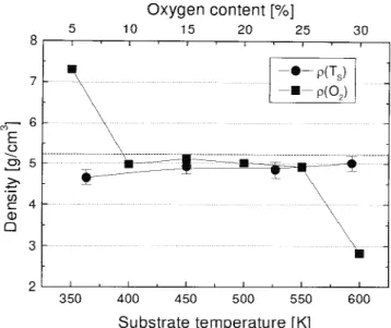
The density of the films is strongly dependent on the process parameters. At 363 K the films show a rather low
density of 4.65 g/cm3 compared to the Cr
2O3 bulk value22 of 5.21 g/cm3(Fig. 2). The density increases at higher substrate temperatures; at 593 K the density reaches almost the bulk value. Very large deviations from this value are observed for the films deposited at very low and very high oxygen contents in the working gas, while at intermediate oxygen partial pressures the density is constant and close to the Cr2O3 bulk density. The value of 7.3 g/cm3 for the film deposited at 5% is near to the bulk value of metallic chromium (7.14 g/cm3). The XRD pattern of this film exhibits peaks of the bcc structure only. The chemical composition measurements revealed only 9% at. oxygen in the film. Therefore, this film can be assigned to metallic chromium with incor-poration of some oxygen in the lattice. At medium oxy-gen contents the densities are very close to the bulk density of Cr2O3, while the 2.8 g/cm
3
of the film depos-ited at 30% oxygen indicates a high porosity.
The chemical composition measurements (Fig. 3) re-vealed that the films deposited with an oxygen content between 10% and 30% of the total gas pressure have a stoichiometry close to Cr2O3. XRD revealed some indi-cations for higher oxides in the film deposited at 30%
oxygen content in the sputtering gas. This phase mixture accounts for the elevated oxygen content in this film. At intermediate oxygen contents in the sputtering gas, the
␣–Cr2O3 phase was the only phase detected by XRD. Within the experimental error of 0.15 for the stoichi-ometric ration, which is mainly due to the uncertainty of the chemical composition of the standards used in EPMA, these films consist of stoichiometric Cr2O3. The substrate temperature also has an influence on the chemi-cal composition. At low substrate temperatures the films are only slightly overstoichiometric. These films are mainly amorphous, but contain some nanocrystalline
FIG. 1. CrOxthin films: deposition rate versus oxygen content in the
sputtering gas (TS⳱ 590 K) and the substrate temperature (at 20%
oxygen content in the sputtering gas).
FIG. 2. CrOxthin films: density versus oxygen content in the
sput-tering gas (TS⳱ 590 K) and the substrate temperature (at 20% oxygen
content in the sputtering gas).
FIG. 3. CrOxthin films: stoichiometric ratio O/Cr versus oxygen
con-tent in the sputtering gas (TS⳱ 590 K) and the substrate temperature
(at 20% oxygen content in the sputtering gas). The solid lines are guidelines for the eye.
grains (crystallite size <7 nm). At 530 K the film is fully crystallized, but is overstoichiometric. At 590 K, a stoi-chiometric crystalline film is finally obtained. In every crystalline Cr2O3 film a compressive residual stresses below 1 GPa was measured.
In Fig. 4 the elastic modulus and hardness values are reported as a function of the substrate temperature. The amorphous films deposited at low substrate temperature exhibit a hardness value of about 20 GPa, which is close to the value reported by Kao et al. for the films deposited at 423 K.23At a substrate temperature of about 500 K, a steep increase in hardness is observed. The maximum hardness values obtained using the Nanoindenter XP and the NHT are 32 and 37 GPa, respectively. The elastic modulus of these films shows a similar dependence on the substrate temperature and exhibits the maximum val-ues of 325 GPa with the Nanoindenter XP and 270 GPa with the NHT.
The hardness and elastic modulus reach the respective maximum values of 31 GPa (hardness) and 325 GPa (modulus) for oxygen partial pressures in the range of 15–25% of the total gas pressure (Fig. 5). At higher oxygen concentrations, both the hardness and elastic modulus decrease to the values of 2.5 and 100 GPa, respectively.
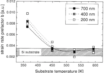
The room temperature creep experiments revealed generally a time dependence of the indenter displace-ment, which at constant load corresponds to the strain⑀, given by⑀ ⳱ a 䡠 t1/3where a is a material and penetration depth dependent prefactor. Therefore, the strain rate⑀. ⳱ (1h)(dh/dt) can essentially be reduced to a strain rate prefactor b⳱ a/h in this case. This allows a simplified comparative discussion of the differences in room tem-perature creeping behavior of the films, as b is time-independent. Differences in the strain rate, and consequently in b, represent differences in the
deforma-tion mechanisms (e.g., crack propagadeforma-tion, delaminadeforma-tion). Yurkov observed remarkable differences in the strain rate (rate of intrusion) in similar experiments on sintered Si3N4and AlN ceramics,
24
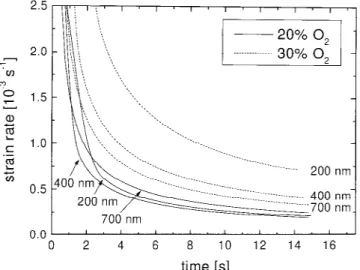
which were attributed to dif-ferences in microstructure and different deformation mechanisms. With respect to thin films differences in b can also indicate a change of the medium (film or sub-strate) in which the deformation predominately takes place. The time dependence of the strain rate changes significantly with the indentation depth in the soft films at maximum oxygen partial pressure while it does not change in the harder films deposited at lower oxygen partial pressures (Fig. 6). The absolute values and the time dependence of the strain rate in the harder films are very similar to those of the Si substrate. The calculated strain rate prefactors of these soft films are about 4 times
FIG. 4. Cr2O3thin films: elastic modulus and hardness versus sub-strate temperature. The films were deposited with 20% oxygen in the sputtering gas on Si substrates. Solid symbols correspond to measure-ments using the Nanoindenter XP, open symbols to values obtained with the NHT. The solid lines are guidelines for the eye.
FIG. 5. Cr2O3thin films: elastic modulus and hardness versus oxygen concentration in the sputtering gas. The substrate temperature was kept constant at 590 K during the deposition.
FIG. 6. Time dependence of the strain rate at constant load at different indentation depths. A hard film deposited with an oxygen partial pres-sure of 20% of the total working gas prespres-sure is compared with a soft film deposited with an oxygen partial pressure of 30%. The substrate temperature during the deposition was in both cases 590 K.
higher at 200 nm, 2 times higher at 400 nm and 25% higher at 700 nm compared to those of the harder films or the Si substrate. With regard to the substrate tempera-ture (Fig. 7), b is reduced to about the value of the Si substrate with increasing TS, but does not vary
signifi-cantly with the indentation depth.
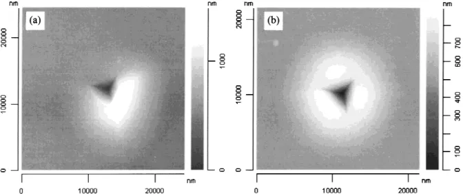
Combined nanoindentation/SFM data provide addi-tional information about the critical loads at which crack-ing and delamination occur. Indentation results (Fig. 8) of the Cr2O3thin film deposited at TS⳱ 360 K and 20% O2partial pressure illustrate that above a critical load of approximately 80 mN the film begins to crack and then completely spalls off the substrate as the load is further increased. This phenomenon is identified by a flat on the loading curve, which corresponds to a stress relaxation and an absorption of energy through the local disintegra-tion process of the film.25At higher loads the measured mechanical properties can therefore be mainly attributed to the Si substrate material. The Cr2O3thin film depos-ited at TS ⳱ 450 K and with 20% O2 partial pressure, represented in Fig. 9, tends to crack laterally away from the indentation site [Fig. 9(a)] and decoheres from the substrate due to the stress at the film/substrate interface. This type of failure is sometimes attributed as pileup, but is clearly due to delamination [Fig. 9(b)] of the coat-ing from the substrate. However, it is important to notice that films deposited at temperatures exceeding 500 K do not exhibit such brittle properties.
IV. DISCUSSION
The mechanical properties of the Cr2O3films strongly depend on the deposition parameters. In particular the hardness and elastic modulus steeply drop for oxygen
partial pressures exceeding 25% of the total gas pressure. SFM analysis confirms the soft nature of such coatings and their randomly oriented polycrystalline structure. For low penetration depths (i.e., less than 10% of the coating thickness), very low hardness and elastic modulus values of 2.6 and 111 GPa, respectively, were measured and coincide with a low density value (∼2.8 g/cm3
) and an increased strain rate prefactor b. This low density value is attributed to high porosity and voids, which re-sult in a lack of coherence of the grains and, conse-quently, in a low hardness value4 and a strong room temperature creeping, At higher penetration depths, the hardness, the elastic modulus and the strain rate prefactor tend toward the values of the Si substrate indicating the strong influence of the substrate on these values. Much higher density values (4.8–5.0 g/cm3) are obtained for films with lower oxygen concentrations. The dense films, especially those deposited at high TS, exhibit high hard-ness (21–37 GPa) and elastic modulus (200–268 GPa) values and a strain rate prefactor close to that of Si. This suggests that the stress relaxation takes place mainly in the comparably softer substrate [H(Si)⳱ 13 GPa] even at very low indentation depths. Films deposited at com-paratively low substrate temperatures are more suscep-tible to cracking at the coating/substrate interface. This is presumably because of stress mismatches and low adhe-sion, which are a result of only limited interdiffusion in the interfacial zone at these temperatures. The creep ex-periments confirm this assumption, as these films show a higher b almost independently of the indentation depth, which leads to the conclusion that the stress relaxation behavior of the substrate merely influences b in this case. This is only possible if the coupling between film and substrate is weak, which is the case in partly delaminated films or if the predominate stress relaxation mechanism is the delamination. Furthermore, SFM images of re-sidual imprints of indentations confirm that interfacial cracking is most prominent in the case of very low sub-strate temperatures (360 K) where the surrounding ma-terial completely delaminates from the Si substrate [see Fig. 8(b)]. By comparing the SFM images of residual indentations made with a maximum applied load of 200 mN, a correlation can be established between the substrate temperature and the extent of delamination around the indentation site: the higher the substrate tem-perature, the lower the effects of subsurface cracking. An explanation for this phenomenon is that the interdiffusion at the film/substrate interface is increased at higher depo-sition temperatures and strengthens the adhesion to the substrate.4
The differences in the absolute values of the hardness and the elastic modulus between the results from the XP and the NHT apparatus (Fig. 4) origin from the differ-ences in the analysis of the raw data. Thereby, the con-tinuous stiffness method has the advantage that it is
FIG. 7. Strain rate prefactor versus substrate temperature during the deposition at different indentation depths. The ≈1.8-m-thick films were deposited with an oxygen partial pressure of 20% of the total sputtering gas pressure. The range of strain rate prefactors of the Si substrate at the different indentation depths were added for comparison.
easier to control the accuracy of the result (usually 10% for the elastic modulus and 5% for the hardness) as it provides data throughout the whole indentation depth. The hardness or elastic modulus values at only little
dif-ferent indentation depths of the same indentation site can be averaged and compared. In addition, the reported val-ues in Fig. 4 represent an average over a different number of indentations (9 in the case of the Nanoindenter XP, 3
FIG. 8. Berkovich indentation data for a Cr2O3thin film deposited at a substrate temperature of 360 K and with a 20% O2sputtering gas concentration. Example (a) shows a 50-mN monocycle, whereas (b) shows the cracking and delamination effects that occur above a critical applied load of approximately 80 mN. At higher loads the measured mechanical properties are almost entirely those of the Si substrate.
FIG. 9. SFM images for indentations made at maximum loads of 200 mN for a Cr2O3thin film deposited at a substrate temperature of 450 K and with a 20% O2sputtering gas concentration. Note the lateral cracking (a) and pile-up/delamination (b) around the indentation site at such high loads.
in the case of the NHT). This illustrates that a quantita-tive comparison of hardness and modulus values meas-ured with a different apparatus and analysis has to be handled with caution.
V. CONCLUSIONS
Regarding the investigation techniques, it is very dif-ficult to determine the true deformation mechanisms oc-curring at the tip-sample interface unambiguously with load-displacement measurements alone. SFM imaging of the residual imprints at various depths is a viable and successful approach to characterize the coating-substrate deformation behavior. In addition, the NHT/SFM com-bination is capable of providing load-displacement data together with topographical information (i.e., surface roughness, extent of pileup/sink-in effects, cracking, true area of contact, volume of material displaced, etc.) in a fast and efficient manner. Additional information on the deformation mechanism can also be deduced from a room temperature creep analysis at constant load.
Regarding the Cr2O3coatings, a clear correlation has been established between the mechanical properties of the tested Cr2O3 thin films and the deposition param-eters. The present study reveals optimum deposition con-ditions with an oxygen content of about 15% in the sputtering gas at substrate temperatures exceeding 500 K. Under these conditions stoichiometric Cr2O3 films are deposited at the highest deposition rates. They exhibit hardness values exceeding 30 GPa while still adhering well to the substrate.
ACKNOWLEDGMENTS
This work was supported by the Fonds National Suisse de la Recherche Scientifique and the Board of the Swiss Federal Institute of Technology (Priority program in Ma-terials Research). Particular thanks are due to C. Zakri and A. Gentile for experimental support and Dr. Franc¸ois Bussy at the Universite´ de Lausanne for the electron probe microanalysis measurements. M. Diserens, J. Michler and A. Karimi are greatly acknowledged for helpful discussions.
REFERENCES
1. G.V. Samsonov, The Oxide Handbook, 2nd ed. (IFI/Plenum, New York, 1982), pp. 192, 195.
2. J.L. Zhang, J. Huang and C. Ding, J. Therm. Spray Technol. 7, 242 (1998).
3. B. Bhushan, G.S. Theunissen, and X. Li, Thin Solid Films 311, 67 (1997).
4. J-E. Sundgren and H.T.G. Hentzell, J. Vac. Sci. Technol, A 4, 2259 (1986).
5. V. Zieren, M.d. Jongh, A.B.v. Groenou, J.B.v. Zon, P. Lansinski, and G.S. Theunissen, IEEE Trans. Magn. 30, 340 (1994). 6. J. Loubet, J.M. Georges, D. Marchesini, and G. Meille, J.
Tribol-ogy 106, 43 (1984).
7. T.F. Page, W.C. Oliver, and C.J. McHargue, J. Mater. Res. 7, 450 (1992).
8. B. Bhushan, V.S. Williams, and R.V. Shack, Trans. ASME J. Tri-bol. 110, 563 (1988).
9. M. Nishibori and K. Kinosita, Thin Solid Films 48, 325 (1978). 10. H.M. Pollock, ASM Handbook (ASM International, Metals Park,
OH, 1992), Vol. 18, pp. 419–429.
11. W.C. Oliver, MRS Bull. XI(5), 15–19 (1986).
12. M.F. Doerner and W.D. Nix, J. Mater. Res. 1, 601 (1986). 13. E.T. Lilleodden, W. Bonin, J. Nelson, J.T. Wyrobek, and
W.W. Gerberick, J. Mater. Res. 10, 2162 (1995).
14. P. Niedermann, J. Burger, M. Binggeli, R. Christoph, H. Hinter-mann, and O. Marti, The Ultimate Limits of Fabrication and
Measurements, edited by M.E. Welland and J.K. Gimzewski
(Proc. NATO ARW, Cambridge, England, 1994).
15. N.X. Randall, R. Christoph, S. Droz, and C. Julia-Schmutz, Thin Solid Films 290–291, 348 (1996).
16. P. Hones, R. Sanjine´s, and F. Le´vy, Surf. Coat. Technol. 94/95, 398 (1997).
17. W.C. Oliver and G.M. Pharr, J. Mater. Res. 7, 1564 (1992). 18. V. Raman and B. Berriche, J. Mater. Res. 7, 627 (1992). 19. M.J. Mayo and W.D. Nix, in Strength of Metals and Alloys, edited
by P.O. Kettunen, T.K. Lepisto¨, and M.E. Lehtonen (Pergamon, Oxford, 1988), p. 1415.
20. N.X. Randall, C. Julia-Schmutz, J-M. Soro, J. Von Stebut, and G. Zacharie, Thin Solid Films 308–309, 297 (1997).
21. G. Reichardt, F. Eggenstein, U. Flechsig, R. Follath, F. Scha¨fers, J. Schmidt, and F. Senf, Groove profiles of soft X-ray diffraction
gratings: AFM measurements, efficiency simulations and meas-urements, European Workshop on Microtechnology and Scanning
Probe Microscopy, 1997.
22. G.F. Samsonov, The Oxide Handbook, 2nd ed. (IFI/Plenum, New York, 1982), p. 19.
23. A.S. Kao, M.F. Doerner, and V.J. Novotny, J. Appl. Phys. 66, 5315 (1989).
24. A.L. Yurkov, J. Mat. Sci. Lett. 12, 767 (1993).