Desian Study of a Novel Computer Instruction Execution Unit
by
Albert Chiou
S.B., E.E.C.S. M.I.T., 2006
MASSACHUSETTS INSTITUTE OF TECHNOLOGYNOV 13 2008
LIBRARIES
Submitted to the Department of Electrical Engineering and Computer Science
In Partial Fulfillment of the Requirements for the Degree of
Master of Engineering in Electrical Engineering and Computer Science
At the Massachusetts Institute of Technology
August 2008
Copyright 2008 Albert Chiou. All rights reserved.
The author hereby grants to M.I.T. permission to reproduce and
to distribute publicly paper and electronic copies of this thesis document in whole and in part in
any medium now known of hereafter created.
-Yi
/7-Author
L/ IJ7pdruIenm
or tiectrlcal Engineering and Computer Science
August 21, 2008
Certified by
-9
Accepted by
Professor Emeritus Jack Dennis
Thesis Supervisor
Arthur C. Smith
Professor of Electrical Engineering
Chairman, Department Committee on Graduate Theses
ARGHMIVtb
t/ .. . . . • . . . . .. . . .L/
,.vDesign Study of a Novel Computer Instruction Execution Unit
by
Albert C. Chiou
Submitted to the
Department of Electrical Engineering and Computer Science
August 21, 2008
In Partial Fulfillment of the Requirements for the Degree of
Master of Engineering in Electrical Engineering and Computer Science
ABSTRACT
The goal of the "Fresh Breeze Project" is to develop a multi-core chip architecture that supports
a better programming model for parallel computing. This architecture combines simultaneous
multithreading, a global shared address space, no memory update, and a cycle-free heap to
provide a platform for robust, general-purpose, parallel computation. These design choices help
simplify classically hard problems such as memory coherency, control flow, and
synchronization. An HDL implementation of the core execution unit of a single processing core
(many cores are on a single chip) forms the basis of further simulation and synthesis. The design
must first be broken down into functional logic blocks and translated into hardware modules.
The language Bluespec Verilog allows this description to be constructed in terms of higher-level
"guarded atomic actions" triggered by a rule based system.
Thesis Supervisor: Jack Dennis
Title: Professor Emeritus
Acknowledgements
I would like to specially thank my thesis advisor Jack Dennis for his support and understanding,
particularly in the tumultuous months of late. I hope that we can continue to collaborate on the
Fresh Breeze project in the future, in hopes of creating some demonstrable results.
I also would like to extend my gratitude to Nirav Dave, who provided extensive help with
Bluespec, as well as getting me in touch with some very useful resources including a dedicated
server. The Bluespec Support team-including Ed Czeck, Steve Allen, and Jacob
Schwartz-was also indispensable in their help with the interpretation of compiler errors and the
implementation of solutions. I would like to also thank Professor Arvind and his grad students,
who were always available. Last, but not least, I would like to send a hearty thanks to Anne
Hunter in the EECS Undergraduate Office, who has helped me in many was throughout my time
Table of Contents
A
bstract
...
3
Acknowledgements
...
4
Introduction ...
6
1
B
ackground ...
7
2
G eneral Overview
...
10
2.1
The Fresh Breeze Chip
...
...
... 10
2.2
Memory System
...
11
2.3
Instruction Set
...
11
3
Single Core Components
...
12
3.1
Function Units
...
13
3.2
Register File
...
13
3.3
M atch System
...
14
3.4
Thread Scheduler
...
15
4
Instruction Flow
...
17
4.1
Q uartet Fetch
...
17
4.2
Instruction Analyze & Dispatch
...
...
18
4.3
Instruction Select, Instruction Issue, and Register File
...
18
4.4
Execute, Buffer, and Writeback
...
... 19
5
HDL Developm ent
...
22
5.1
H ardw are Setup
...
22
5.2
From Functional Description to HDL Code
...
23
5.3
Fresh Breeze M odule
...
...
... 24
5.4
Dependence and ActDepend
...
24
5.5
Coordinator and CoordStage
...
... 25
5.6
IResourceBuffer
...
26
5.7
Instruction Stages
...
... 27
5.8
The Testbench Module
...
...
... 29
5.9
Compiling and Debugging
...
29
6
Current Status and Future Work
...
... 31
R eferences
...
... .
32
Appendix A - "mkTestbench.bsv"
...
... 33
Appendix B
-
"mkFreshBreeze.bsv"
...
... 35
Appendix C
-
"Dependence.bsv"
...
... 67
Appendix D
-
"Coordinator.bsv"
...
... 81
Appendix E
-
"Instructions.bsv"
...
106
Appendix F
-
"IResourceBuffer.bsv" ...
...
122
Appendix G - "mkResourceBuffer.bsv"
...
123
Appendix H
-
"IntFuncUnit.bsv"
...
129
Introduction
As silicon technology advances in leaps and bounds, computer architectures have become
almost exclusively multiprocessor, as this allows performance to be increased by simply
increasing the processor count. At the same time, software programming practice is only now
beginning to make the slow transition from sequential to parallel paradigms. Historically, the
complexity of parallel programming has relegated it to the niche of industrial scale applications
running on specialized Distributed Control Systems. We contend that the problems of parallel
programming are largely due to an architectural lack of adherence to core principles of modular
software construction. In this context, the Fresh Breeze Project aims to develop a multi-core
architecture that supports a more robust programming model for computing [1]. My thesis
project is a study of the execution core of this novel architecture with the goal of developing an
RTL model in Bluespec Verilog. Using the Bluespec Verilog language allows the project to use
industry standard tools to perform simulations and to synthesize hardware.
1
Background
There are six principles of modular software construction in particular that are often
violated by computer architectures. They are as follows:
"1. Information Hiding Principle: The user of a module must not need to know
anything about the internal mechanism of the module to make effective use of it.
2. Invariant Behavior Principle: The functional behavior of a module must be independent
of the site or context from which it is invoked.
3. Data Generality Principle: The interface to a module must be capable of passing any data
object an application may require.
4. Recursive Construction Principle: A program constructed from modules must be usable
as a component in building larger programs or modules.
5.
Secure Arguments Principle: The interface to a module must not allow side-effects on
arguments supplied to the interface.
6. System Resource Management Principle: Resource management for program modules
must be performed by the computer system and not by individual program modules." [2]
In order to address the aforementioned six principles while providing superior
performance over current architectures, the Fresh Breeze project will employ the following
concepts: simultaneous multithreading, a global shared address space, no memory updates, and a
cycle-free heap. [3]
To achieve maximum efficiency, all components must be performing useful and
meaningful tasks at all times, which is not possible with simple single-threaded in-order
operation. Individual threads will at some point need to wait upon memory access latencies, and
it is clear that this "dead time" could be spent doing something else-in particular, working on
another thread. Thus with multithreading, it is possible to amortize the cost of long latencies
across many threads, and in the ideal case, eliminate it completely.
Another source of inefficiency lies in the fact that many modem computers use
specialized hardware to execute different types of instructions despite the fact that only a single
instruction is being executed at any given moment. This means that all hardware not involved in
the computation are wasting their time in idle instead of contributing to the completion of
instructions. We can reduce this inefficiency by extending our idea of concurrency across the
many different function units. In this case we note that the function units are operationally
independent, so they can simultaneously execute independent instructions, which can easily be
found by choosing instructions from independent threads. Thus we can see that a
"simultaneous" and "multithreaded" architecture is a promising start in the search for
increasingly efficient computer architectures. These are just two properties that the Fresh Breeze
architecture leverages in order to exploit parallelism at multiple levels [3].
Looking back at the six principles, the Information Hiding Principle and the Invariant
Behavior Principle have been largely accepted for a number of years, as exemplified by the
proverbial "black box" which pervades all pedagogical materials in both software and hardware
curriculums. These two principles are simply asking that we build constructs which can be
described completely in terms of their inputs and outputs. In conforming to the System Resource
Management principle, which dictates that the hardware manage system resources such as data
storage, we can reason that a global address space should be used. Notions of"files" and
the Operating System knows about and the hardware has no control over. Additionally, this also
violates the Data Generality Principle since instructions cannot be executed on "file" operands.
The use of 64-bit pointers should allow for ample room to uniquely address all data, whether in
temporary storage like memory or non-volatile storage such as disk drives.
Adherence to the Secure Arguments Principle, which disallows any "side effects" on
arguments passed to a module, results in more interesting conclusions. The motivation of the
principle is to avoid the non-determinacy present when a program module modifies data shared
with another module running concurrently. The means adopted in the Fresh Breeze project to
ensure satisfaction of the Secure Arguments Principle is to rule out any updating of data objects
in memory. Fixed chunks of data will be allocated, released, and garbage collected by hardware
means. Additionally, problems of cache coherence are eliminated.
2
General Overview
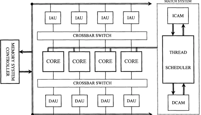
2.1 The Fresh Breeze Chip
A single Fresh Breeze chip consists of multiple processors and memory blocks integrated
with a Thread Scheduler, two CAMs (Content Addressable Memory), and a memory
interface/controller (see fig. 1). The primary means of on-chip communication is through two
crossbar switches that allow for concurrent point-to-point communication among the processors,
data memory, and instruction memory. At this point, we imagine that one chip would have about
8 processors and about 16MB of memory, split into multiple banks designated for instructions
(Instruction Access Units) or data (Data Access Units). Each processor core supports four
Activities, or active threads, and each Activity has exclusive use of 32 registers in the Register
File.
MATCr-I VTEM
Figure 1 General Layout of a Fresh Breeze chip
...
2.2 Memory System
The basic unit of storage is 1024 bits, which is referred to as a "chunk." There are two
types of chunks: data chunks, which contain program data, and code chunks, which contain
program code. Chunks are addressed by a 64-bit UID (Unique ID) that maps to its location in
physical memory. On the chip, chunks reside in either the IAUs (Instruction Access Units) or
DAUs (Data Access Units) based on their type. Processing cores can access data in the Access
Units at the word level by using 14-bit "Locations," which are assigned to "chunks" by the
ICAM (Instruction CAM) and DCAM (Data CAM) when the chunks are copied into on-chip
memory from the Shared Memory System.
4.3 Instruction Set
The Fresh Breeze Architecture is a load/store type, and this is reflected in its relatively
simple instruction set which operates almost exclusively on the Register File. Instructions are 32
bits wide, with up to two operands and one destination specified by 5-bit Register File addresses
or an immediate value. An Immediate value is a bit literal in an instruction, and can be in
different places and have different numbers of bits depending on the instruction. The actual data
operands can be 64- or 32-bit, and can be used for integer or floating point instructions. The
opcode is 10 bits, and encodes both the operation to be executed as well as a number of
properties of the instruction, such as if a test condition should be checked or if the result will be
written back to the Result Buffer. In addition to the normal computational instructions like
addition, shifting, and bitwise-OR, other instructions supported include conversion operations,
predicated move operations, thread and flow control instructions, and memory instructions.
3
Single Core Components
Figure 2 Functional block diagram of a single Fresh Breeze processor core.
This section will explore some of the main components of a single Fresh Breeze
core-the Function Units, Register File, Match System, and Thread Scheduler (see fig. 2). The rest of
the core components will be described in the next section as the flow of an instruction through
the core is traced from start to finish.
3.1 Function Units
Each processor has five Function Units--one FP (floating point) multiply unit, one FP
add unit, two integer units, and a load/store unit. The Function Units have registered inputs, and
their results are buffered independently. Inputs can come from the register file, instructions in
the form of immediate values, or they can be bypassed from one of the result buffers, which store
data waiting to be written back to the register file (only the last
1two entries in each Result Buffer
are considered for bypass). Additionally, Function Units of the same type--either integer or
floating point--can bypass values to each other. Assumed latencies are one cycle for the integer
units, two for the floating point adder, and three for the floating point multiplier; loads and stores
do not have fixed latencies.
3.2 Register File
The Register File is interleaved into eight discrete banks of sixteen 32-bit registers.
These banks are grouped into four sections, each consisting of a "left" and "right" bank. Each
register can hold either a 32-bit data value, half of a 64-bit data value, or half of a 64-bit UID.
Associated with every pair of "left" and "right" registers is an independently accessible 14-bit
field used for storing Locations. Physically separate from the Register File is the Register
Properties Table, which contains the following bits of information for each left-right pair of
registers: a left and right "data valid" bit, a left and right "UID valid" bit, and a "location known"
1
The "last" entry in a buffer is referring to the most recently added entry, which is also the last entry to be serviced.
Similarly, the "first" entry in a buffer would be the least recently added entry, and the first entry to be serviced.
bit. This last bit indicates that the Location of the UID stored in the register pair is known and
stored in the aforementioned 14-bit field. The separation of the Register File, Register Properties
Table, and Location registers allows the processor to validate UID references and access the
corresponding Locations without interfering with normal access to the Register File.
To access the Register File, each of the eight banks has three independent read ports and
one write port. For each bank, one of the read ports is exclusive to the Load/Store Unit, while
the other two read ports are available for accessing operands. Of the two remaining read ports,
one is dedicated for the loading of A-operands and the other for B-operands. For the most part,
this is accomplished by direct wiring of instruction source fields to address lines of their
respective ports. The only exception is in the case of a two operand instruction in which the
A-operand is specified by an immediate value, since the B-A-operand must then be specified by the
source 0 field. Similarly, "left" and "right" banks normally load data into the corresponding
halves of operand registers in the case of 64-bit values, but for 32-bit values, the left bank must
provide the right side of an operand for odd addresses
2.
The write port is shared between the
Load/Store Unit and the Result Buffers, with the former always having priority. In the Result
Buffer, older entries have priority over newer entries if there is a conflict in bank access.
Between the eight banks, the entire Register File can support up to 16 reads and 8 writes
simultaneously each cycle.
3.3
Match System
The Match System consists of the Thread Scheduler and CAMs, and communicates to the
Match Interface Units on the processors through the Match Response and Match Command
Networks shown in figure 2 above. The Match Interface Unit of a particular processor can
2
For 32-bit instructions, all operands are stored in the "right" side of the operand registers.
receive match requests from either the Fetch Unit or the Load/Store Unit when that unit needs to
access a chunk it does not know the Location of. Every clock cycle, each Match Interface Unit
scans all pending and incoming match requests and selects one of them to service, with higher
priority generally assigned to requests from the Load/Store Unit. Once this is done, the chosen
unit must then negotiate with any other Load/Store or Fetch Units also competing for control of
the Match Bus. When it finally has control of the bus, it can then issue a match request
containing the 64-bit UID of its target chunk to the appropriate CAM. If the CAM has the
Location of the 64-bit UID, it will respond with it on the Match Response Bus. Otherwise, the
CAM must retrieve the chunk from the Shared Memory System and assign it a Location, which
is then sent on the Match Response Bus to the unit that made the request. The unit then stores
the location locally-the Load/Store Unit in the Register File and the Fetch Unit in a Code
Segment Map-to avoid having to re-issue future match requests for the same 64-bit UID.
The Match System is also connected to the Invalidate Bus and the Chunk Mark Bus,
which are used to communicate information to the processor cores regarding the usage of 64-bit
UIDs. In particular, the Data Mark Bus is used to determine when a chunk has fallen out of use
so its location may be allocated to another chunk and its 64-bit UID. The Invalidate Bus is used
by the Match System to query whether processors are still using a particular chunk.
3.4
Thread Scheduler
The Thread Scheduler is responsible for mediating the starting, stopping, and swapping
of threads in the processor cores of the chip. Its principal method for doing this is by
maintaining a list of pointers to ASRs, or Activity Status Records, for all threads, either dormant
or ready for assignment to a processor Activity slot. An ASR contains all data necessary for the
operation of a thread-the UID of the code segment, the UID of the FAR segment, the UID of
the chunk with the contents of the Register File, and an additional field filled with the program
4
Instruction Flow
The operation of the processor can be broken down into a number of phases. In logical
order, they are: Fetch, Analyze and Dispatch, Select, Issue, Register File, Execute, Buffer, and
Writeback. These are described below in detail to provide a functional description which forms
the basis of our HDL code.
4.1
Quartet Fetch
Instructions are 32-bits, and reside in on-chip memory in the form of code chunks stored
in the IAUs (note that these chunks could have been moved on-chip from main memory). They
are fetched four at a time, if possible, from the Access Units via the Fetch Command and Fetch
Response Networks. Of the four active threads allowed in a core, the Fetch Unit selects one and
attempts an instruction fetch from the Location and offset in the "program address" for that
Activity. If for any reason four instructions cannot be fetched (e.g. if the current activity only
has 3 more instructions), "NOP"s are added until a group of four is formed. If the end of a chunk
is reached upon fetch, the Location of the next code chunk must be retrieved from the Code
Segment Map in the Fetch Unit. Once four instructions and found, they are bundled together
with valid bits and their activity number into a single unit called a Quartet. New Quartets
arriving from the Access Units are placed immediately into the Quartet Buffer. If any of the
Resource Buffers become full, fetching of Quartets is suspended, and any Quartets still in transit
are either enqueued if buffer space is available or discarded if not (an appropriately sized buffer
should ensure that Quartets will never need to be discarded).
4.2
Instruction Analyze & Dispatch
Each instruction in a Quartet will ultimately be processed by a single Function Unit. In
order for a Quartet to leave the Quartet Buffer, there must be an empty rank in all of the
Resource Buffers corresponding to the Function Units that will execute the instructions in the
Quartet. When this condition is met, the instructions are Dispatched to the appropriate Resource
Buffers, and their information is passed to the Dependence Unit for Decoding. Each of the five
Resource Buffers is organized as a matrix of registers with four "ranks" and four "files," and
their role is to store the instructions waiting to be executed by their associated Function Unit.
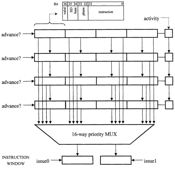
Upon Dispatch into a Resource Buffer, each instruction is tagged with a "valid" bit, and the new
rank is given a 2-bit Instruction ID (IID) prefix, a phase bit, and a 2-bit number which specifies
the Activity which the instructions in the rank are a part of. The 4-bit IID of a particular
instruction can be constructed by using the IID prefix as the upper two bits and the rank offset as
the lower two bits. The phase bit, which is changed every time 16 IIDs are assigned, is used to
help distinguish between older and newer instructions.
Meanwhile, the Dependence Unit extracts dependence information from the sources and
targets of each instruction, which it records in the Instruction Dependence Matrix. This
information is then passed along with the rest of the processor state to the Coordinator, which
Analyzes the data in order to schedule Register File port access and control instruction flow.
4.3
Instruction Select, Instruction Issue, and Register File
Every clock cycle an instruction in a Resource Buffer can, in decreasing priority, be
Selected to the Instruction Window (IW) if there is sufficient space, advance to the next rank if
that rank is empty, become invalidated if the control flow changes (such as a branch taken), or
otherwise do nothing. Each Function Unit is only allocated a pair of registers in the Instruction
Window, which is sufficient since each cycle only one instruction per Function Unit-and thus
per pair-can be Issued. It is one of the duties of the Coordinator to decide which instructions to
Issue, based on a combination of operand availability and a balance between Register File
utilization and fair sharing of computational resources between the activities.
Issued instructions are moved to their Function Unit's Instruction Advance register or
Instruction Delay register, depending on if the operand loading will take one or two cycles,
respectively. This decision is also made by the Coordinator, and can occur if not enough
Register File read ports are available in the current cycle. This process of loading operands is the
called the Register File stage since most operands come from the Register File. Operands can
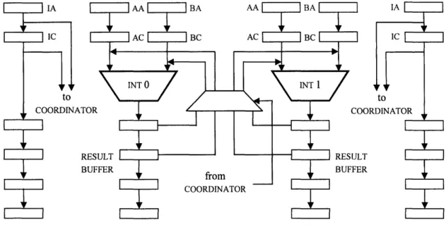
also be supplied as immediate values within instructions or bypassed data from the Result
Buffer. A Function Unit can only receive bypassed operands from the last or next-to-last entries
of its own Result Buffer, or the Result Buffer of the other function unit that it shares a type with.
In other words, Integer Function Units can bypass data to each other and Floating Point Function
Units can bypass to each other, but operands cannot be bypassed from Integer to Floating Point
or vice versa (see fig. 3a, 3b).
4.4 Execute, Buffer, and Writeback
Once the operands are loaded, the Execute phase begins, which is when the actual
command described by the instruction's opcode is run. Integer Function Units will complete any
operations within a cycle, but the Floating Point adder take two cycles and the Floating Point
multiplier takes three. The result of an operation, when ready, is Buffered along with its target
Register File address in the Result Buffer belonging to the Function Unit it came from. If any
valid Condition Codes were generated in the operation, they are stored in the Condition Code
registers. The Condition Codes are used to indicate certain conditions in the Function Unit or its
result, such as "positive" or "negative," "equal to 0" or "not equal to 0," "overflow," and "divide
error." This information is only used by predicated instructions like conditional branches.
Figure 3a Bypass logic and Result Buffers for the INT Function Units
A
St
F[
If the instruction is a load or store instruction, the Load/Store Unit then checks the
"known" flag of the target register. If set, the Load/Store Unit can get the 14-bit Location
directly from the Register File and immediately access the addressed DAU through the Access
Command Network. Otherwise, the Register File only contains the 64-bit UID of the desired
chunk, so the Load/Store Unit must first issue a match request to the Match Interface Unit to get
its Location. Once the Location is returned, the Load/Store Unit stores it in the Register File and
sets the "known" flag before completing the instruction.
The instruction could also alter control flow or be a predicated move, which passes either
the A operand or the B operand to the Result based on the state of the Condition Code registers.
The predicated move is particularly useful as it allows one to avoid the penalty of restarting
instruction fetch when a branch is taken. For instance, instead of executing a branch to decide
which set of instructions to execute next, one could compute the result of both sets of
instructions and then execute the predicated move which would select the "correct" answer.
While Predicated move instructions are handled by the integer units, control flow instructions
like jump or branches can be handled by a small amount of logic within the coordinator, as it
also schedules instruction issue. If a jump or branch occurs, the activity's PC in the Fetch Unit is
set to the address given by the instruction; in the case of a branch, an extra step involves
invalidating any instructions fetched after it, and to fetch and enqueue new instructions.
After Execution, any Function Unit results are placed in the Result Buffer, where they are
made available as bypass operands if they are in the last two registers. In the Writeback stage,
up to eight results can be written to the Register File, if their target banks do not conflict. If there
is a conflict between entries, the older entry gets priority. If the Result Buffers ever get full, they
signal the Coordinator to stop issuing instructions.
5
HDL Development
Figure 4 Block diagram of hardware under test
5.1
Hardware Setup
The actual hardware that is modeled is the core execution unit of a single processing unit,
shown in figure 3 above. The Load-Store Unit, "matching" hardware, and all external
connections have been removed, leaving only the modules that are directly involved in the
execution of individual non-memory instructions. What we are left with, this "core execution
unit," are the modules responsible for the fetch and issue of instructions, the loading of operands,
5.2
From Hardware Description to HDL Code
Bluespec Verilog is a high-level HDL language that is built upon a hierarchy of modules
which interact through method calls triggered by a rule-based system. Each module presents an
"interface" which controls all communication between the module and the external world. These
interfaces consist primarily of a collection of methods, which can perform actions on internal
state and/or return data. Local state in the modules takes the form of storage elements like
registers and FIFOs, and return data must be in the form of a bit field. Additionally, each
module can contain its own set of rules which define its internal behavior. These rules are
activated when their predicated conditions are met, and may freely modify the internal state of
the module. [4]
How this translates into cycle-to-cycle behavior is as follows: at the beginning of a cycle,
all rules whose conditions are met are scheduled to "fire" in some order. Once all the scheduled
rules have fired, all updates to state elements occur and the next cycle begins. The power of
Bluespec, and thus the source of its complexity, lies in its ability to optimize actions and
interactions by "smart" rule scheduling that attempts to maximize concurrency. The price of
leveraging this power, however, is that you must relinquish cycle-accurate control. Thus, a
compromise is required to allow us to implement the optimized behavior integrated into our
design while still leaving room for the compiler to do its own optimization.
To do this, we sidestepped most of the internal complexity of Bluespec by modeling the
processor as a module with a single "run" method. Having all actions in a single method allows
us to control the exact order in which they occur, allowing us to avoid some common sources of
underperformance such as wasted register load cycles
3. It may be worthwhile in the future to
explore a restructuring of the code would more completely leverage the rich Bluespec feature set,
as it may uncover further optimizations that are hard to see in large, complex systems. In the
next section the module implementations in Bluespec will be described, and an analysis of the
design options available at each point will be provided.
5.3
Fresh Breeze Module
The entire Core Execution Unit contains a fairly broad and shallow hierarchy of modules,
with the mkFreshBreeze module at the top. This module has two functions
4and two
methods-one which runs the processor, and methods-one which dumps the internal state to a file (appendix A).
Additionally, there are a number of storage elements and submodules, which generally
correspond to the component blocks seen in figure 3. The actual code of the main processor
method can be broken down into sections that correspond to the aforementioned stages of the
instruction cycle.
5.4
Dependence and ActDepend
The Dependence module basically consists of a Vector of ActDepend module instances,
and a collection of methods that allow you to access the methods of these modules in various
ways (either iterating over all of them, or calling a particular one). There is one ActDepend
module for each activity, and it is in these modules that the Instruction Dependence Matrix and
Register Matrix reside. The main methods of the ActDepend module include methods for the
allocation and de-allocation of instruction IDs, the "analyze" method that extracts dependence
3
Often in HDL design, registers or latches will be created in unexpected places, causing a one cycle delay to load
the storage element.
4
Functions encapsulate frequently used operations, much like their software analogs.
information from instructions, and the methods responsible for manipulating the "scoreboard"
5,
which tracks register file access so the Coordinator can schedule future access. The Dependence
Unit is used during the Quartet Analysis and Decode phase to check for valid instructions and
extract instruction properties, in the Issue stage to set the Scoreboard bit that indicates a pending
write, and in the Writeback stage to clear the "write pending" bit set during Issue.
5.5
Coordinator and CoordStage
The Coordinator module contains the control logic necessary to Select RB instructions to
move to the
IW,
Issue instructions from the
IW,
load operand registers, schedule Register File
access, and stage instructions to arrive at the FUs together with their operands. The control
signals for all these tasks are generated by a single "operate" method, which takes as its input the
Instruction Window contents, the dependence information for all activities, information on
pending writes from the scoreboard, and bypass information from the appropriate registers
(shown in fig. 3a and 3b). The operate method checks resource needs of each instruction in the
IW
against the availability of FUs and RF banks.
The Coordinator module is made up eight CoordStage modules, each corresponding to an
entry in the Instruction Window, and a collection of registers keeping track of RF and FU
availability. Each CoordStage module has its own operate method, which the Coordinator
iterates over in its own operate method. The only local state is a register of 6 bits to help keep
track of delayed read operations if an instruction's operands require two cycles to load.
5
The scoreboard keeps track of RF usage by setting bits in a matrix whenever a read or write begins. These bits are
cleared once the read or write has been completed.
Bi
1313 343 323
Cua l instructionactivity.
advance?
advance?
advance?
advance?
INSTRUCTIONWINDOW
issueO-
]
Figure
5
Detailed view of a single Resource Buffer (RB)
issuel
5.6 IResourceBuffer
The IResourceBuffer module, used for the Resource Buffers, consists of four "files" of
four "ranks," as previously described in this paper. Figure 4 illustrates the internals of a single
Resource Buffer. The storage elements consist of the four ranks and the additional metadata
required for each rank. The methods provide functionality for retrieving the values of the storage
elements, adding new ranks, and "updating" the RB state, which consists of clearing Selected
and invalid instructions and advancing all ranks that are able.
... O0
5.7 Instruction Stages
The Fetch stage consists only of the logic that adds incoming Instruction Quartets to the
Quartet Buffer and reports to the testbench when the buffer is full (how this is done will be
explained in the Testbench section). The uncomplicated Quartet Buffer was implemented using
an unmodified, built-in sized-FIFO primitive of Bluespec; all we wanted was a way to buffer
incoming Quartets, so we chose the simplest method available. In the Analyze and Decode
stage, the Quartet at the head of the Quartet Buffer is Decoded and its dependence information
extracted before its instructions are Dispatched to the Resource Buffers. Each instruction is sent
to the RB of the Function Unit that will execute it; if there is more than one Function Unit that
can process an instruction, it is sent to the RB with the least number of occupied ranks. This
helps to balances the computational load between the RBs, as well as the number of instructions
in an RB contending for selection at any one moment.
As the instructions are being Dispatched, The dependence and decode information is
bundled with information regarding bypass operand availability, outstanding Register File writes
(which is one of the things kept track of in the Dependence Unit's "scoreboard"), and the
Instruction Window contents, and everything is sent to the Coordinator for Analysis. When
done, the Coordinator will output signals that will be used to control register file access,
instruction issue, and the complex process of loading operands.
Once instructions are in the RB, they compete for Selection to the IW, with older
instructions given higher priority. The "rank" and "file" mechanism of the RBs is meant as
something of a funnel for incoming instructions, so given a program with an even distribution of
instruction types, the Resource Buffers are expected to be relatively sparsely filled. We could
not use a linear FIFO for the RBs because it would have to support up anything between zero and
four enqueues every cycle. The solution is to always enqueue four instructions at a time,
invalidating the ones that will not be executed by the RB's Function Unit. You also have to
advance the instructions four at a time to leave room for new instructions, and leave invalid
instructions in the FIFO, since their removal would create the unnecessary complexity of
allowing every entry to advance to any position ahead of it. If you modified a FIFO with all
these corrective behaviors, you would end up with a Resource Buffer. The "rank" and "file"
expression is simply a more understandable way to visualize the RB's operation.
When Selected, instructions are moved into the Instruction Window, which has two slots
for each Function Unit (FU) and Resource Buffer pair, meaning up to two instructions can be
Selected from each RB in a single cycle. However, since only one of any FU's instructions is
Issued at a time, in most cases only a single instruction per RB is Selected in a cycle. When an
instruction is in the Instruction Window, instructions wait to be Issued by the Coordinator. Once
they are, the Coordinator begins the process of loading the operands necessary for the execution
of the current set of instructions. We call this phase the Register File phase because that is the
primary source of operands. Operands can also come in the form of immediate values in the
instruction or they can be bypassed from the Result Buffers. Only the last two slots of each
Result Buffer are allowed to make their results available for bypass. Additionally, Function
Units of the same type can bypass data to each other-in other words, the Integer Function Units
can bypass data to each other (see fig. 3a), and the Floating Point Function Units can bypass data
to each other (see fig. 3b). One important thing to keep in mind is that the operands to be
considered for bypassing are the results that will be in the Result Buffer at the time of execution,
so in making the decision to Issue an instruction, you have to check the target registers of the
appropriate instruction in the pipeline. From Issue to Execution, an integer operation with a
bypassed operand will take 2 cycles, so you must look at the instruction two cycles back in the
pipeline. Figure 3a and figure 3b illustrate this-the signals labeled "to coordinator" indicate the
registers which are being examined for possible use as a source of a bypassed operand.
5.8 The Testbench Module
The Testbench module is a wrapper around the processor core that will feed it
instructions and collect processor information which will be written to a file. Its basic setup
includes a "count" rule that always triggers and steps the processor forward one clock cycle. At
the end of every cycle, the display method of the Fresh Breeze Core Execution Unit is called and
the processor state is saved to a file. The simulation can end if either (1) an instruction is fetched
with all is, (2) a fixed number of cycles has gone by, or (3) an invalid or contradictory state is
reached in the processor. Error information is passed from the Fresh Breeze unit to the
Testbench by a 32-bit return value called the haltcode, whose individual bits represent the
occurrence of various halt conditions. If the haltcode is ever nonzero, an error has occurred, so
the processor state is written to a file one last time followed by the haltcode, and the simulation
ends. Analysis of the haltcode and the history of processor state should allow one to determine
the exact nature of the condition which caused the malfunction.
5.9 Compiling and Debugging
The Bluespec compilation process involves a number of stages in static elaboration,
linking, and code generation. The most frequent errors encountered were excessively long
compilation times due to scheduling, out of memory errors, and function unfolding issues. These
three problems are closely tied together, and can be traced back to the scheduling and static
elaboration strategies that Bluespec uses.
In static elaboration, functions undergo a process called function unfolding in which each
function call is resolved in its local context, often by a simple text-substitution since every call
usually corresponds to a separate hardware instance. This is a problem when large iterative
structures are used, as the process of function unfolding quickly becomes a time- and
memory-consuming task. In particular, those used to abstraction with functions will find that strategy
leading to programs that will not completely compile. Our approach was to minimize such
iterative loops to only a few lines, or to limit the number of iterations of more complex loops.
While statements were eliminated completely, as even the simplest ones seemed to create
compilation problems.
Type matching was also a frequent problem, as Bluespec is very strict in resolving
mismatched types. Interaction between variables and storage elements was a particular conflict
that was common, as was a conflict between the Integer and Bit types. Integer types are resolved
in the static elaboration phase, so they are ideal as indices for iterative loops. However, one
could not always use the index in the loop since other places you would use an index, such as for
vectors, require the Bit type, which is distinct from the Integer type. Occasionally, type
conversions could be used to resolve the difference, but an easier solution was to use a Bit type
variable as the index, despite the possibility of generating unintended hardware.
6
Current Status and Future Work
The project is currently still in the debugging phase. Some of the issues encountered in
compiling have been discussed, and there are ongoing efforts to resolve them, with the hope of
having a full simulation ready within weeks. Currently our code only supports integer
instructions, and the plan is to wait until we have a working simulation before adding the floating
point Function Units. This would at least allow us to verify that all other parts of the code are
correct before going on. Additionally, it would make the debugging work much easier by
introducing new code incrementally instead of all at once.
Farther into the future, the plan is to integrate a JAVA viewer into the Bluespec
simulation that would allow you to observe and interact with the processor in real-time as it
executes instructions. This would allow us to demonstrate in a clear and visible fashion the
effectiveness of the Fresh Breeze design. The main goal in the coming weeks and months is to
get a bug-free simulation developed that will produce consistent results which can be compared
to other architectures of its class. Until we can get concrete data from the simulation of
meaningful computation, the Fresh Breeze project will remain in the realm of theory and
possibility.
References
[1]
J. B. Dennis, "Fresh Breeze: A Multiprocessor Chip architecture Guided by Modular
Programming Principles," ACM Sigarch News, Mar. 2003.
[2]
J. B. Dennis, "A Parallel Program Execution Model Supporting Modular Software
Construction," In Third Working Conference on Massively Parallel Programming
Models, pp. 50-60, 1998
[3]
Dennis, J. B., "The Fresh Breeze Model of Thread Execution," presented at PACT-2006
Workshop on Programming Models for Ubiquitous Parallelism. Seattle, WA, 16 Sep.
2000.
[4]
Bluespec, Inc., BluespecTM System Verilog Reference Guide, [Online document], Rev:
20007 March 30, [cited 2008 Aug 21], Available HTTP:
Appendix A
"mkTestBench.bsv" package mkTestbench;// import list
import RegFile ::*; import mkFreshBreeze :: interface ITestbench; endinterface: ITestbench module mkTestbench(ITestbench);// ############################# Elements & State ##############################
//
Counter
Reg#(Bit#(6)) count <- mkReg(0); Reg#(Bit#(32)) haltcode <- mkReg(0);
Reg#(File) dump <- mkReg(InvalidFile);
// Instruction Memory
RegFile#(Bit#(6), Quartet) instrMem <- mkRegFileFullLoad("instr.txt");
// Processor
IFreshBreeze freshBreeze <- mkFreshBreeze();
//
##################################
RULE(S)
##############################
rule init ((haltcode == 0) && (count == 0));
File t <- $fopen("fbreeze.out", "w"); dump <= t;
endrule
rule stop (haltcode != 0);
freshBreeze.displayState(dump); $fdisplay(dump);
$fdisplay(dump, "************** END *************** haltcode = %b", haltcode);
$fclose (dump); $finish(l); endrule
rule operate ((haltcode == 0) && (count > 0));
freshBreeze.displayState(dump); let newQuartet = instrMem.sub(count);
if (newQuartet == 134'h3fffffffffffffffffffffffffffffffff) haltcode <= 32'hffffffff; else begin Bit#(32) z; z <- freshBreeze.run (newQuartet); haltcode <= z; end endrule
rule counting (haltcode == 0);
count <= count + 1;
endrule
//
###########################
METHOD(S) endmoduleAppendix B
"mkFreshBreeze.bsv"
/*
haltcode specifications:
Bit
0 : Quartet Buffer Full
1 : Issue Conflict -> Del/Adv instruction reg - instruction issued to Instruction Advanced register at the same time instruction moving there from Instruction Delay register
2 : RF current data read - bad valid bit 3 : RF current address read - bad valid bit 4 : RF advanced data read - bad valid bit 5 : RF advanced address read - bad valid bit 6 : Bypass data invalid FUO
7 : Bypass data invalid FU1
8 : Bypass data invalid FU2
9 : Bypass data invalid FU3
10: Conflict - double/single at FU output 11: Invalid instruction
*/
package mkFreshBreeze;// Import List
import Vector ::* import FIFOF ::*; import RegFile ::*; import Instructions ::* import Dependence ::*; import Coordinator ::*; import IResourceBuffer ::import mkResourceBuffer : import IntFunctUnit :
// Data Types
typedef Bit#(32) typede f Instruction; structVector#(4, Instruction) instructions; Vector#(4, Bool) valid;
Bit#(2) activity;
} Quartet deriving (Bits, Eq); typedef struct
Vector#(8, Reg#(Instruction)) instr; Vector#(8, Reg#(Bool)) valid;
Vector#(8, Reg#(Bit#(4))) instrID; Vector#(8, Reg#(Bit#(2))) activity;
) InstructionWindow;
interface IFreshBreeze;
// Execute
method ActionValue#(Bit#(32)) run(Quartet newQuartet);
method Action displayState (File z);
endinterface: IFreshBreeze
(* synthesize *)
// ########################### Elements & State ############################
// Quartet Buffer
FIFOF#(Quartet) quartetBuffer <- mkUGSizedFIFOF(4);
// Resource Buffers
Vector#(4, IResourceBuffer) resourceBuffer <- replicateM( mkResourceBuffer() );
// Dependence Unit
Dependence dependenceUnit <- mkDependence();
// Coordinator
Coordinator coordinatorUnit <- mkCoordinator();
// Instruction Window
InstructionWindow instructionWindow;
instructionWindow.instr
<-
replicateM(mkReg(0));
instructionWindow.valid
<-
replicateM(mkReg(False));
instructionWindow.instrID
<-
replicateM(mkReg(0));
instructionWindow.activity <- replicateM(mkReg(0));
// Operand
Vector# (4,
Vector#(4,
Vector#(4,
Vector#(4,
Vector#(4,
Vector#(4,
Vector#(4,
Vector# (4,
Vector#(4,
Vector# (4,
Vector#(4,
Vector# (4,
Vector#(4,
Vector#(4,
Vector#(4,
Vector#(4,
Vector#(4,
Registers
Reg#(Bit#(32)
Reg#(Bit#(32)
Reg#(Bit#(32)
Reg#(Bit#(32)
Reg#(Bit#(32)
Reg#(Bit#(32)
Reg#(Bit#(32)
Reg#(Bit#(32)
Reg#(Bit#(32)
Reg#(Bit#(32)
Reg#(Bit#(32)
Reg#(Bit#(2))
Reg#(Bit#(2))
Reg#(Bit#(2))
Reg#(Bool)) d Reg#(Bool)) a Reg#(Bool)) cadvAL
advAR
advBL
advBR
curAL
curAR
curBL
curBR
delI advI <-curl<-dellIact
advIact
curIact
LelIvalid
dvIvalid
urIvalid
replicateM(
replicateM(
replicateM(
replicateM(
replicateM(
replicateM(
replicateM(
replicateM(
mkReg
mkReg
mkReg
mkReg
mkReg
mkReg
mkReg
mkReg
(0)
(0)
(0)
(0)
(0)
(0)
(0)
(0)
replicateM( mkReg(0)
)
replicateM( mkReg(0)
)
replicateM( mkReg(0)
)
<- replicateM( mkReg(0) <- replicateM( mkReg(0) <- replicateM( mkReg(0)replicateM(
replicateM(
replicateM(
mkReg(False)
mkReg(False)
mkReg(False)
// Function Units
FunctionUnit funcInt0 <- mkIntFunctionUnit() ;
FunctionUnit funcIntl <- mkIntFunctionUnit() ;
FunctionUnit funcFloatAdd <- mkIntFunctionUnit() ;
FunctionUnit funcFloatMul <- mkIntFunctionUnit() ;
// Condition Code Registers
Vector#(4, Reg#(Bit#(4))) conditionCode <- replicateM( mkReg(0) );
// Register File address registers
Vector#(4, Reg#(Bit#(5))) leftAddresses0 <
Vector#(4, Reg#(Bit#(5))) leftAddressesl <
Vector#(4, Reg#(Bit#(5))) rightAddresses0 Vector#(4, Reg#(Bit#(5))) rightAddressesl
Vector#
Vector#
Vector# Vector# Reg# Reg# Reg# Reg# (Bool)) (Bool)) (Bool)) (Bool)) replicateM( mkReg(0) replicateM( mkReg(0) replicateM( mkReg(0) replicateM( mkReg(0)leftAddressesValid0 <- replicateM( mkReg(False) leftAddressesValidl <- replicateM( mkReg(False) rightAddressesValid0 <- replicateM( mkReg(False) rightAddressesValidl <- replicateM( mkReg(False)
// Register File
Vector#(4, RegFile#(Bit#(4), Vector#(4, RegFile#(Bit#(4),
Bit# (32))) Bit# (32)))
registerFileLeft <- replicateM( mkRegFileFull()); registerFileRight <- replicateM( mkRegFileFull()); Vector#(4, Vector#(4, RegFile#(Bit#(4), RegFile#(Bit#(4), // Result Buffers Vector#(4, Vector#(4, Vector#(4, Vector#(4, Vector#(4, Vector#(4,
Bool)) registerFileLeftValid <- replicateM( mkRegFileFull()); Bool)) registerFileRightValid <- replicateM( mkRegFileFull());
Reg#(Bit#(32)))) Reg#(Bit#(32)))) Reg#(BypassInfo)
resultBufferLeft <- replicateM( replicateM( mkReg(0) )); resultBufferRight <- replicateM( replicateM( mkReg(0) ));
)) resultBufferData <- replicateM( replicateM( mkReg(unpack(0)) ));
//
###########################
METHOD(S)method ActionValue#(Bit#(32)) run(Quartet newQuartet);
// ********** Cordinator ********** // Setup Coordinator input
Integer i, j; Bit#(32) ii, jj;
CoordInput coordinatorInput = unpack(0); RegFileAddress destination0, destinationl;
Vector#(4, Bit#(16)) dependenceInfo = dependenceUnit.getDependence(); Vector#(4, Bit#(32)) writePending = dependenceUnit.getWritePending();
// Check for illegal instructions
if ((newQuartet.valid[0]) && !(makeDecodedInstruction(newQuartet.instructions[0) .illegal))
haltcode[l] = 1;
if ((newQuartet.valid[l]) && !(makeDecodedInstruction(newQuartet.instructions []).illegal))
haltcode[ll] = 1;
if ((newQuartet.valid[2]) && !(makeDecodedInstruction(newQuartet.instructions[2]).illegal)) haltcode[1l] = 1;
if ((newQuartet.valid[31) && (makeDecodedInstruction(newQuartet.instructions [3]).illegal)) haltcode[ll] = 1;
for (i = 0; i < 8; i = i + 1) begin
coordinatorInput.instr window[i].valid = instructionWindow.valid[i]; coordinatorInput.instr window[i] .instruction =
makeDecodedInstruction(instructionWindow. instr [i]);
coordinatorInput.instr_window[i] .activity = instructionWindow.activity[i]; coordinatorInput.instr window[i].iid = instructionWindow.instrID[i];
end
ii = 0;
for (i = 0; i < 4; i = i + 1) begin
destination0 = getDestination(curI[il); destinationl = getDestination(advI[i]);
coordinatorInput.dependence [i] = dependenceInfo[ii [1:0]]; coordinatorInput.write_pending[i] = writePending[ii[l:0]]; coordinatorInput.bypass info_0[i] .act = curIact[i];
coordinatorInput.bypass info0 [i] .pair = destinationO[4:1];
coordinatorInput.bypass_info_0 [i] .left = !unpack(destinationO[0]); coordinatorInput.bypass info 0[i] .right = unpack(destinationo [0]); coordinatorInput.bypass info 1[i] .act = advIact[i];
coordinatorInput.bypass_info 1[i] .pair = destinationl[4:1];
coordinatorInput.bypass info_l 1[i] .left = !unpack(destinationl[0]); coordinatorInput.bypass infol [i] .right = unpack(destinationl [0]);
ii = ii + 1;
end
// Saving Coordinator output
CoordOutput coordinatorOutput <- coordinatorUnit.operate(coordinatorInput);
// ********** Resource Buffers -> Instruction Window **********
// finding first, second free instructions Bit#(5) index0, indexl;
Bool select0 = False; Bool selectl = False;
Vector#(4, Bool) adv = replicate(False);
Bit#(2) sel = 0; Vector#(16 Vector#(16 Vector#(16 Vector#(4, , Bool) rbv = replicate(False);
, Instruction) rbi = replicate(0);
, Bit#(4)) rbiid = replicate(0); Bit#(2)) rba = replicate(0);
// iterated across FUs
for (i = 0; i < 4; i = i + 1) begin
rbv = (resourceBuffer[i]) .getValid();
rbi = (resourceBuffer[i]) .getInstructions(); rbiid = (resourceBuffer[i]) .getIID();
rba = (resourceBuffer[i) .getActivity();
index0 = first(rbv); indexl = second(rbv);
// Selecting from RB to IW
let slot0 = 2*i; let slotl = 2*i + 1;
// first -> slot0
select0 = (index0[4] == 0)
&& (!instructionWindow.valid[sloto] // first -> slotl OR second -> slotl
selecti = ((index0[4] == 0)
&& (instructionWindow.valid[sloto] && (coordinatorOutput.issued[slot0] == 0)) && (!instructionWindow.valid[slotl] (coordinatorOutput.issued[slotl] == 1)))
((indexl[4] == 0)
&& (!instructionWindow.valid[slotl] (coordinatorOutput.issued[slotl] == 1)));
// note "second -> slot0" is impossible since you need a first before you can have a second;
if (!instructionWindow.valid[slot0] (coordinatorOutput.issued[slot0] == 1)) if (index0[4] == 0) begin // first -> slot0 (instructionWindow.instr[slot0]) <= rbi[index0 [3:0]]; (instructionWindow.valid[slot0]) <= True; (instructionWindow.instrID[slot0]) <= rbiid[index0[3:0]]; (instructionWindow.activity[slot0]) <= rba[index0 [3:2]];
if ((indexl[4] == 0) && (!instructionWindow.valid[slotl]
I
(coordinatorOutput.issued[slotl] == 1))) begin // second -> sloti (instructionWindow.instr[slotl]) <= rbi[indexl[3:0]]; (instructionWindow.valid[slotl]) <= True; (instructionWindow.instrID[slotl]) <= rbiid[indexl[3:0]]; (instructionWindow.activity[slotl]) <= rba[indexl[3:2]]; end endelse if ((index0[4] == 0) && (!instructionWindow.valid[slotl]
I
(coordinatorOutput.issued[slotl] == 1))) begin // first -> slotl (instructionWindow.instr[slotl]) <= rbi[index0[3:0]]; (instructionWindow.valid[slotl]) <= True; (instructionWindow.instrID[slotl]) <= rbiid[index0[3:0]]; (instructionWindow.activity[slotl]) <= rba[index0[3:2]]; end// Updating RBs
if (select0) if (selectl) sel = 2; else sel = 1; else if (selectl) sel = 1;else
sel = 0;
adv[i] <- resourceBuffer[i] .update(sel); end
// ********** Quarter Buffer -> Resource Buffers **********
let first =
let proceed if (proceed)// get
Bit#(2) quartetBuffer.first(); = (dependenceUnit.freeInstrId(first.activity) &&quartetReady(first, resourceBuffer[0], resourceBuffer[l],adv)); begin
IIDs
id base <- dependenceUnit.allocate( first.activity, pack(first.valid) );
// get activity
Bit#(2) activity = first.activity;
Vector#(4, Vector#(4, Vector #(4
Instruction) newInstr = replicate(0); Bool) newValid = replicate(False);
Bit#(3)) rbAssign = replicate(0);
for (i = 0; i < 4; i = i + 1)
if (first.valid[i])
rbAssign[i] = assignToRB(first.instructions[i] , resourceBuffer[O], resourceBuffer[l]); else rbAssign[i] = 3'b100; for (i = 0; i < 4; i = i + 1) begin newInstr = first.instructions; newValid = first.valid; for (j = 0; j < 4; j = j + 1)
if (newValid[j] && (rbAssign[i] != fromInteger(i))) newValid[j] = False;
resourceBuffer[i] .addRank(newInstr, newValid, id base, activity); end
quartetBuffer. deq ();
// call dependence unit, pass in Instructions
Vector#(4, Bit#(1)) z;
Vector#(4, DecodedInstruction) analyzeInput; for (i = 0; i < 4; i = i + 1)
if (first.valid[i]) begin z[i] = 1;
analyzeInput [i] = makeDecodedInstruction(first.instructions[i]); end
else
z[i]= 0;
dependenceUnit.analyze ({z([3], z[2], z[1] , z[0]}, activity, analyzeInput); end
// ********** Quartet Fetch **********
if (newQuartet.valid[0]
I
newQuartet.valid[l] newQuartet.valid[21 newQuartet.valid[3])if (quartetBuffer.notFull ())
quartetBuffer.enq(newQuartet); else
haltcode[0] = 1;
// ********** Loading Operand Registers *******
// Loading Instruction Registers (Delayed, Advance, Current)
Integer x;
for (x = 0; x < 4; x = x + 1) begin
// Delayed
if (coordinatorOutput.load instr 0 delayed[x] == 1) begin
(delI [x]) <= instructionWindow.instr[2*x] ; (delIact [x]) <= instructionWindow.activity[2*x]; (delIvalid[x]) <= True; dependenceUnit.releaseIdentifier(instructionWindow.activity[2*x], instructionWindow. instrID [2*x]); end
if (coordinatorOutput.load instr I delayed[x] == 1) begin (delI [x]) <= instructionWindow.instr [2*x + 1]; (delIact[x]) <= instructionWindow.activity[2*x + 1]; (delIvalid[x]) <= True; dependenceUnit.releaseIdentifier(instructionWindow.activity[2*x + 1], instructionWindow.instrID[2*x + 1]); end
//
Advance
if (coordinatorOutput.load instr 0 advance[x] == 1) begin
if (!delIvalid[x]) begin (advI [x] ) <= instructionWindow.instr[2*x]; (advIact [x]) <= instructionWindow.activity[2*x] ; (advIvalid[x]) <= True; dependenceUnit.releaseIdentifier(instructionWindow.activity[2*x], instructionWindow. instrID [2*x]); end else haltcode[l] <= 0; end
if (coordinatorOutput.load_instr 1 advance[x] == 1) begin if (!delIvalid[x]) begin (advI [x]) <= instructionWindow.instr[2*x + 1]; (advIact[x]) <= instructionWindow.activity[2*x + 1]; (advIvalid[x]) <= True; dependenceUnit.releaseIdentifier(instructionWindow.activity[2*x + 1] , instructionWindow.instrID [2*x + 1]); end else haltcode[l] <= 0; end
// Delayed -> Advance (when no Advance reg is written to)
if ((coordinatorOutput.load instr 0 advance[x] == 0)
&& (coordinatorOutput.load_instr 1 advance[x] == 0) && delIvalid[x]) begin
(advI [x] ) <= delI [x];
(advIact[x]) <= delIact[x];
(advIvalid[x]) <= True;
if ((coordinatorOutput.load instr 0 delayed[x] == 0) && (coordinatorOutput.loadinstr1 delayed[x] == 0))
(delIvalid[x]) <= False;