HAL Id: insu-01312620
https://hal-insu.archives-ouvertes.fr/insu-01312620
Submitted on 7 May 2016
HAL is a multi-disciplinary open access archive for the deposit and dissemination of sci-entific research documents, whether they are pub-lished or not. The documents may come from teaching and research institutions in France or abroad, or from public or private research centers.
L’archive ouverte pluridisciplinaire HAL, est destinée au dépôt et à la diffusion de documents scientifiques de niveau recherche, publiés ou non, émanant des établissements d’enseignement et de recherche français ou étrangers, des laboratoires publics ou privés.
Wave spectrum retrieval from SWIM data: speckle
spectrum estimation Session: ” Wave retrieval and
applications ”
Danièle Hauser, Lauriane Delaye, Thomas Grelier, Cédric Tourain, Céline
Tison, Patrick Castillan
To cite this version:
Danièle Hauser, Lauriane Delaye, Thomas Grelier, Cédric Tourain, Céline Tison, et al.. Wave spectrum retrieval from SWIM data: speckle spectrum estimation Session: ” Wave retrieval and applications ”. Living Planet Symposium 2016, May 2016, Prague, Czech Republic. �insu-01312620�
Wave spectrum retrieval from SWIM data: speckle spectrum estimation Session: “Wave retrieval and applications”
Authors: D. Hauser, L. Delaye, T. Grelier, C. Tourain, C. Tison, P. Castillan 1. Introduction
The Chinese and French Space Agencies propose to jointly carry out an innovative mission, CFOSAT (China France Oceanography Satellite project) devoted to the monitoring of the ocean surface and its related science and applications. CFOSAT will embark both a wind and a wave scatterometers, enabling a simultaneous measure of the wind and the wave vectors with a global coverage for the first time. The launch is planned for mid-2018.
The satellite embarks two payloads; both are Ku-band radar scanning around the vertical axis:
- the wave scatterometer SWIM, a rotating 6-beams radar at small incidence (0 to 10°) [1, 2],
- the wind scatterometer SCAT, a fan-beam radar at larger incidence angles (30° to 50°) [3].
This paper focuses on the processing of the SWIM data for the retrieval of the 2D wave spectrum and, especially the estimation of the speckle spectrum.
2. Overview of the SWIM data processing
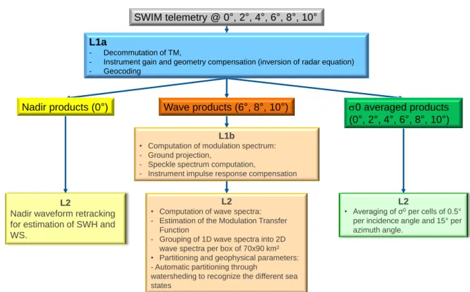
Figure 1. Overview of the SWIM L1 and L2 products and the associated processing.
The SWIM data are of three kinds [4]: the normalized radar cross-section profiles from 0° to 11°, the SWH and wind speed from the nadir beam and the wave spectrum from the 6°, 8° and 10°. The processing steps are following:
- inversion of the measured power to normalized radar cross section (inversion of the radar equation) and geolocalization of each radar gate,
L2
• Computation of wave spectra: - Estimation of the Modulation Transfer
Function
- Grouping of 1D wave spectra into 2D wave spectra per box of 70x90 km² • Partitioning and geophysical parameters: - Automatic partitioning through
watersheding to recognize the different sea states
L2
• Averaging of σ0per cells of 0.5° per incidence angle and 15° per azimuth angle.
L1b
• Computation of modulation spectrum: - Ground projection,
- Speckle spectrum computation,
- Instrument impulse response compensation
L2
Nadir waveform retracking for estimation of SWH and WS.
SWIM telemetry @ 0 , 2 , 4 , 6 , 8 , 10
L1a
- Decommutation of TM,
- Instrument gain and geometry compensation (inversion of radar equation) - Geocoding
Nadir products (0 ) Wave products (6 , 8 , 10 ) 0 averaged products (0 , 2 , 4 , 6 , 8 , 10 )
- estimation of averaged normalized radar cross section per step of 0.5° in incidence and 15° in azimuth,
- retracking of the nadir waveform to estimate the SWH and the wind speed,
- estimation of the modulation spectrum from the 0 fluctuations and correction of the spectrum from speckle and impulse response,
- computation of the wave spectrum from modulation spectrum through the computation of the modulation transfer function.
There are two major issues: the estimation of the speckle spectrum and the estimation of the modulation transfer function. The paper addresses the issue of the speckle spectrum.
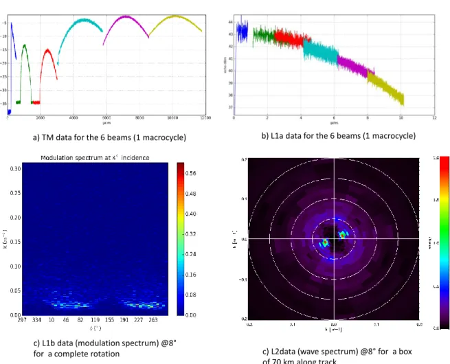
Figure 2. Illustrations of the SWIM products for wave spectrum computation.
3. Estimation of the speckle spectrum
The wave spectrum is estimated from the density spectrum of the fluctuation of the backscattering coefficient. This density spectrum is equal to [1, 2, 5]:
𝑃𝛿𝜎0= 1 2𝜋∫ 〈𝛿𝜎0(𝑥, 𝜙)𝛿𝜎0(𝑥 + 𝜉, 𝜙)𝑒−𝑖𝑘𝜉𝑑𝜉〉 𝑃𝛿𝜎0(𝑘, 𝜙) = 𝛿(𝑘) + 𝑅(𝑘)𝑃𝑚(𝑘, 𝜙) + 1 𝑁𝑖𝑚𝑝𝐿𝑑𝑖𝑠𝑃𝑠𝑝(𝑘) + 1 𝑁𝑖𝑚𝑝𝐿𝑑𝑖𝑠𝑃𝑏(𝑘)
with 0 the backscattering coefficient fluctuations (due to the long slopes), R the spectrum of the radar impulse response, Pm the modulation spectrum (linearly linked to the wave spectrum), Psp the spectrum speckle, Pb the thermal noise spectrum, Nimp the number of pulses averaged in time, Ldis the number of averaged range gates. The aim is to estimate Pm.
a) TM data for the 6 beams (1 macrocycle) b) L1a data for the 6 beams (1 macrocycle)
c) L1b data (modulation spectrum) @8°
for a complete rotation c) L2data (wave spectrum) @8° for a box
The speckle spectrum depends on the real number of independent pulses [5]. The dependency of the spectrum to the sea state conditions is still under investigation. Three main methods are used:
- analytical methods,
- estimation from the noise floor, - use of cross-spectrum computation.
The three methods will be detailed and discussed. 4. Results on simulated data and airborne data
The three methods have been tested on simulated data and on real airborne data. The results will be shown and discussed.
Figure 3. Illustrations of speckle estimation with different methods.
5. References
[1] Enjolras V., L. Rey, T. Amiot, C. Tison, P. Castillan, SWIM, a state of the art multi-incidence beams Ku-band waves scatterometer to go beyond current radar systems, in IGARSS’09, July 2009
[2] Hauser, D., Soussi, E., Thouvenot, E., and Rey, L.,“SWIMSAT: a real aperture radar to measure directional spectra of ocean waves from space main characteristics and performance simulation”. Jour. Atmos. Oceanic Tech., 18, 2001
[3] Zhu J., X. Dong, W. Lin, X. Xu, Calibration and estimation of attitude errors for a rotating fan-beam scatterometer using calibration ground stations, IEEE JSTARS, PP(9), 2014
[4] C. Tison, D. Hauser, L. Delaye, T. Koleck, N. Lamquin, M. Planells, F. Gouillon, P. Castillan, Processing of the CFOSAT-SWIM data: algorithm prototyping and simulations, IGARSS’15, 2015
[5] D. Hauser, G. Caudal, R. Valentin, C. Legac, N. Pauwels, C. Tison, A study of speckle properties over the ocean surface from the airborne radar Kuros, ENVIREM, Gif-sur-Yvette (France), 9-10 Juin 2015
Nominal mode
Speckle mode
a) Nominal mode: PSP1a= analytical formula, PS2a: estimation from noise floor with k >0.2m-1, PSP2b: estimation from noise floor in half a rotation (direction with no waves)
a) Speckle mode (3 dowloaded averaged power per cycle instead of one per cycle): PSP1a= analytical formula, PSP2b: estimation from noise floor in half a rotation (direction with no waves), PSP4: difference of fluctuation spetra from the same cycle