HAL Id: hal-02396214
https://hal.archives-ouvertes.fr/hal-02396214
Submitted on 11 Dec 2020
HAL is a multi-disciplinary open access
archive for the deposit and dissemination of
sci-entific research documents, whether they are
pub-lished or not. The documents may come from
teaching and research institutions in France or
abroad, or from public or private research centers.
L’archive ouverte pluridisciplinaire HAL, est
destinée au dépôt et à la diffusion de documents
scientifiques de niveau recherche, publiés ou non,
émanant des établissements d’enseignement et de
recherche français ou étrangers, des laboratoires
publics ou privés.
Analysis of the Gamma Irradiation Effect on PTFE
Films by FTIR and DSC
N. Saidi-Amroun, Virginie Griseri, S. Mouaci, A. Mezouar, G. Teyssedre, M.
Saidi
To cite this version:
N. Saidi-Amroun, Virginie Griseri, S. Mouaci, A. Mezouar, G. Teyssedre, et al..
Analysis of
the Gamma Irradiation Effect on PTFE Films by FTIR and DSC. IEEE Conference on
Electri-cal Insulation and Dielectric Phenomena (CEIDP 2018), Oct 2018, Cancun, Mexico. pp.430-433,
�10.1109/CEIDP.2018.8544841�. �hal-02396214�
Analysis of the Gamma Irradiation Effect on PTFE
Films by FTIR and DSC
N. Saidi-Amroun
1, V. Griseri
2, S. Mouaci
1, A. Mezouar
1, G. Teyssèdre
2, M. Saidi
11Material Physics Laboratory, University of Sciences and Technology (USTHB), Algiers, Algeria 2 LAPLACE, Université de Toulouse, UPS, CNRS, Toulouse, France
Abstract – Dielectric materials can be used in radiative
environment that is why it is of major importance to determine their properties modifications with time. In this paper we focus our attention on PolyTetraFluoroEthylene (PTFE) films submitted to gamma radiations. We investigate the FTIR spectra and show that after exposure to Co60 the crystallinity of the
material is increasing. This result is confirmed by Differential Scanning Calorimetry (DSC) analysis. Some space charge distribution profiles obtained by the Pulse Electro Acoustic (PEA) method show that the irradiation favours the drift of injected charges toward the bulk. Obviously the dose of radiation must be carefully chosen in order to be able to perform electrical measurements. Indeed, we observed that if the radiation dose is too high the sample becomes fragile and most of the characterisation tools cannot be used.
Keywords— PTFE, FTIR, DSC, space charge, gamma irradiation,
I. INTRODUCTION
Dielectric materials that are commonly used as electrical insulation can be submitted to various sources of radiation that might modify their electrical properties with time. It is therefore important to understand their behaviour after different periods of ageing.
In this paper, we have selected one type of polymeric film the PolyTetraFluoroEthylene (PTFE) which is used for space applications for its high temperature withstanding. Many measurements have been performed on PTFE after electron irradiation [1]. It has been observed that such type of material is able to store charges for long period of time. In this work the samples have been submitted to one source of gamma radiation and analysed after exposure to different doses. We have chosen to use only one source of radiation at a time to be able to relate the physico-chemical modifications to one parameter.
In the next section we present results obtained by Fourier Transform Infrared spectroscopy -FTIR and Differential Scanning Calorimetry -DSC. We show that changes that are directly linked to the radiation can be detected. However the analysis of the space charge profiles by the Pulse Electro-Acoustic -PEA system presented in the following section shows little changes in space charge behaviour in the entire sample bulk. It means that even if the polymeric chains are physically damaged, the charge storage and conduction processes are little affected.
II. SAMPLE SELECTION AND EXPERIMENTAL SET-UP
A. Samples and Irradiation Conditions
For this set of experiments, commercially available PTFE (supplied by Goodfellow) films have been selected. Two sample thicknesses (50 and 200 µm) have been chosen because they are convenient for the characterisation tools we are using.
The samples have been irradiated in air at room temperature with a 60Co gamma radiation source available at the Nuclear
Research Centre of Algiers with a dose rate of about 22 Gy/min. Samples are supposed to be homogenously crossed by the gamma radiations.
The aim is to compare the experimental data obtained on virgin sample and samples submitted to 60 and 600 kGy. The deposited dose is directly dependent on the irradiation time. The order of magnitude of the irradiation was between a few days and a few weeks.
B. Fourier-Transform Infra-Red Spectroscopy
In order to investigate the effect of the gamma irradiation on the PTFE sample chemical structure, FTIR measurements have been performed. The equipment used is a VERTEX 70 fully digital infra-red (IR) spectrometer designed for data acquisition in the mid Infra-Red region (400 - 4000 cm-1) with
a resolution of 2 cm- 1. All the spectra have been recorded on
Virgin and irradiated samples using the transmission mode. C. DSC Analyses
To analyse the thermal response of virgin and irradiated PTFE a TA Instruments Q2000 Differential Scanning Calorimeter has been used. Samples of c.a. 10 mg weight were enclosed in aluminium pans. A classic protocol consisting in two successive cooling/ heating scans has been followed. In the present case a temperature range from -120 up to 150 °C with a cooling/heating rate of 10 °C/min has been applied. The experiments are performed under a nitrogen atmosphere to avoid any thermal degradation.
D. Space charge measurements
To follow the space charge distribution during the polarization the classic PEA set-up [2, 3] available in the laboratory has been used. The measurements were performed at atmospheric pressure at a controlled temperature of 25°C. During the measurements the sample is sandwiched between two set of electrodes. The polarization voltage was applied through the top electrode on which a semiconducting layer
2400 2200 2000 1800 1600 1400 1200 1000 800 600 400 0.0 0.2 0.4 0.6 0.8 Virgin PTFE 600 kGy PTFE Ab so rba n c e ( a .u) Wavenumber(cm-1) CF 2 C O O H C OF Amorphous phase CF 3 -C F =C F 2
Fig. 1. Global FTIR spectra recorded on virgin and gamma irradiated (Dose 600 kGy) PTFE in transmisison mode.
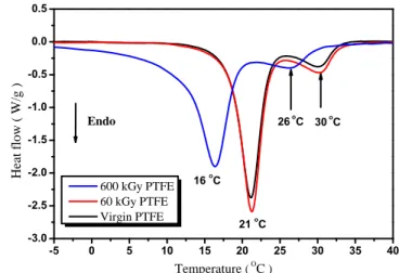
-5 0 5 10 15 20 25 30 35 40 -3.0 -2.5 -2.0 -1.5 -1.0 -0.5 0.0 0.5 16 oC 21 oC 30 oC 26 oC Heat flow ( W/g ) Temperature ( OC ) 600 kGy PTFE 60 kGy PTFE Virgin PTFE Endo
Fig. 2. Differential Scanning Calorimetry thermograms of virgin PTFE and gamma irradiated samples (60 and 600 kGy) obtained under a
heating rate of 10 °C/min.
(carbon black doped polymer) -semicon is attached. The bottom part of the sample is in contact with the grounded Aluminium bottom electrode.
Space charge density profiles were recorded for 1 h while the sample was polarized under a field of 40 kV/mm. Afterwards, the signal was recorded for an extra hour under Volt-off to probe the charge release.
The first set of charge density profiles was recorded on a virgin sample of 200 µm thick then the experiment was repeated on the 60 kGy irradiated sample. Unfortunately the sample submitted to the higher dose could not be characterized as it was very brittle and only too small pieces were available for the analyses.
III. EXPERIMENTAL RESULTS AND DISCUSSION
A. FTIR Spectroscopy
The effects of gamma radiation on FTIR spectra being milder at lower irradiation dose (60 kGy), only the results obtained with the higher dose (600 kGy) are compared herein to the virgin one. FTIR spectra of 600 kGy irradiated and virgin PTFE samples are shown in Fig. 1
The FTIR spectra are dominated by two bands at 1199 and 1146 cm-l (not visible in the figure due to enlargement)
attributed to the -CF2 asymmetrical and symmetrical stretching
[4]. The band at 2364 cm-l was assigned to a combination band
of two modes associated with the CF2 backbone [5]. Its
increase in the case of irradiated sample results from the chain scission induced by gamma irradiation. The appearance of the band located at 1884 cm-l is attributed to the COF group, its
formation is due to the presence of the oxygen during the irradiation. Also, a much greater absorption was observed at 1810 and 1776 cm-l in irradiated PTFE. These bands are
associated to the free and bonded carbonyl stretching of carboxylic acid end groups (COOH), respectively [6]. The presence of these ends groups indicates that oxidation reactions have occurred. The presence of moisture during irradiation may have cause an increase of the band.
In addition, the existence of double bonds or crosslinked structure, assigned to band at 1792 cm-l (-CF=CF
2) [7] in
virgin PTFE, apparently disappeared during the irradiation. The new group appearing at 986 cm-l is assumed to arise from
CF3 terminations [4, 8]. It has a relatively weak intensity
compared to the other new groups mentioned previously (COF and COOH). The kinetics of CF3 formation starts with the
scission of the main chain producing a pending group CF2,
which recombines with an ionized F atom, which was initially split from the chain.
The FTIR spectra show that the virgin PTFE has a crystalline phase revealed by the presence of the peaks 553, 625, 638 cm-l due to the CF
2 group [9]. On the other hand, the
effect of the irradiation appears in the decrease or the disappearance of the amorphous phase manifested by the absorption bands in the region between 700 and 800 cm-l [10].
B. DSC results
Figure 2 summarizes the DSC analyses of virgin and irradiated PTFE (0 and 600 kGy). The DSC thermograms show two endothermic peaks associated to solid-solid transitions located at about 21 and 30 °C, also called "first-order transition" in PTFE. The first peak corresponds to the transition from the triclinic phase to the hexagonal phase whereas the second one reflects the phase transition from hexagonal to pseudo-hexagonal. The positions of the peaks are in very good agreement with the literature [11, 12].
Both peaks show a shift by about 5 °C towards lower temperature in the case of the sample submitted to the highest irradiation dose (600 kGy). These peaks remain unaffected in the case of lowest dose (60 kGy).
In the previous section, it was shown that PTFE undergoes a structural modification mainly due to degradation during gamma rays [13]. This is reflected by the presence of carbonyl groups and the disappearance of the amorphous region of PTFE [14]. Therefore, these results reflect to some extent that defects are induced by exposure to 600 kGy radiation dose to cause chain scissions and relieve the residual stresses shown in the amorphous region, which, in turn .will cause some increase in molecular mobility and allow the molecules to
a) Virgin sample Volt On and OFF
b) Sample after Gamma irradiation 60 kGy. Volt ON
Fig. 3 : Charge density profile recorded by the classic PEA set-up on a PTFE 200 µm thick a) Virgin sample during 1 h Polarisation under 40 kV/mm and 1 h relaxation and b) After gamma irradiation 60 kGy
during 1 h polarisation under 40 kV/mm.
Fig. 1. Global FTIR spectrum recorded on virgin and gamma irradiated (Dose 600kGy) PTFE in transmisison mode.
-20 0 20 40 60 80 100 120 140 160 180 200 220 240 -30 -25 -20 -15 -10 -5 0 5 10 Volt OFF Charge densi ty (C/m 3) Distance (µm) Volt ON -20 0 20 40 60 80 100 120 140 160 180 200 220 -35 -30 -25 -20 -15 -10 -5 0 5 10 Charge densi ty (C/m 3) Distance (µm) rearrange themselves [14, 15]. This relaxation of the structure
can explain that the main first order transition at 20 °C for irradiated PTFE (a triclinic structure to a well-ordered hexagonal structure) appears 5 °C lower after irradiation. Recently Fu et al. [16], in their study of electron beam irradiation effect on room temperature transitions, have reported that the lowering of transition temperatures with doses was attributed to the combined effects of main chain scission and formation of degradation products. They assumed that the decrease of crystal-crystal transition of PTFE should be due to the irradiation-induced new side groups and their content variations.
On the other hand in can be noticed from Fig. 2 that the peak area (and hence the enthalpy) associated to the first solid-solid transition is higher than that of the higher temperature transition. This can be explained by the high energy required to change the crystalline symmetry from triclinic to hexagonal, in comparison to the transition between hexagonal and pseudo-hexagonal symmetry as reported by Marega et al. [17]. This behaviour is similar for all the samples, i.e. irradiation does not apparently change the capabilities of PTFE to crystalline in a given crystalline form.
C Space charge distribution profiles
Initially the space charge profile has been recorded on a non-irradiated PTFE sample. The charge density profile reported in Fig. 3.a shows a negative peak on the left (at the interface sample/detection electrode) and a positive peak on the right (at the interface sample/excitation electrode). These peaks are associated to the polarization voltage which is creating an internal field of 40 kV/mm and capacitive charges on both electrodes. We notice that both peaks are not symmetrical because there is an attenuation effect of the signal through the bulk due to the sample nature and possibly also due to acoustic impedance mismatch with the semicon electrode. In the bulk of the sample no charges are detected while the field is applied. As there is no charge injected, no residual charges are detected to relax during the volt off period of 1 h. The small peak that is observed on the back electrode side after volt off is attributed to the electrostriction phenomenon which is due to the pulse voltage application.
In Fig. 3.b we have reported the space charge profile recorded under the same conditions on a sample that has been exposed to 60 kGy radiation. It can be noticed that during the polarization a small amount of negative charges is detected in the bulk. After short-circuiting (Volt-Off), the relaxation of the charges was very fast. Unfortunately, the thicker 600 kGy sample was too brittle to be measured by PEA. We notice that the thinner sample (50 µm thick) irradiated also with 600 kGy was not so fragile but could not be measured by the classic PEA cell as the resolution is not sufficient.
The 60 kGy dose does not create enough damages in the structure to provide a large amount of conductive path or traps. The same conclusion was made from the DSC results. To complete this set of experiments we do plan to work on samples that are exposed to intermediate doses to keep the sample in shape for the measurement. Besides, to perform
measurements on thin sample it is possible to work with a PEA cell offering a better resolution [18]. Finally in order to study the space charge distribution in thin sample we may also use the Laser Intensity Modulated Method -LIMM that has already been recently developed to work under applied voltage conditions [19].
IV. CONCLUSION
In this work the modification of the crystallinity due to Gamma irradiation in PTFE sample has been shown. The of gamma radiation dose needs to be relatively important to detect important damages in the sample to be detected by physico-chemical measurements. At this stage of the analysis, the changes observed are attributed to a scission effect. Obviously further work is necessary to define more precisely from which dose the effect is preponderant.
To go further, it will be important to select samples and irradiation conditions that can be analysed by PEA method. The aim of the work remains to establish links between the
effect of the irradiation and the charge transport in the bulk. In real situations other parameters such as temperature, electric field and other sources of damages need to be taken into consideration. This type of work will be developed in further research project.
ACKNOWLEDGMENT
The authors are grateful to the Director and staff (especially M. R. Yefsah) of the Nuclear Research Centre of Algiers for the provision of the irradiation facility. The work is supported by French-Algerian Tassili research program in the frame of Partenariat Hubert Curien (PHC).
REFERENCES
[1] X.T. Nguyen, V. Griseri and L. Berquez, “In-Situ space charge measurements on dielectrics during electronic irradiation by PEA”, Proc. IEEE Int. conf. on Insulation and Dielectric Phenomena (CEIDP), pp. 226-229, Shenzhen-China, Oct. 2013.
[2] T. Takada, T. Maeno, and H. Kushibe, “An electric stress-pulse technique for the measurement of charges in a plastic plate irradiated by an electron beam,” IEEE Trans. Electr. Insul., vol. 22, pp. 497–501, 1987.
[3] T. Maeno, T. Futami, H. Kushibe, T. Takada and C. M. Cooke, "Measurement of spatial charge distribution in thick dielectrics using the Pulsed Electroacoustic method," IEEE Trans. Electr. Insul., vol. 23, pp. 433-439, 1988.
[4] A. Oshima S. Ikeda, E. Katoh and Y. Tabata, “Chemical structure and physical properties of radiation-induced crosslinking of polytetrafluoroethylene,” Radiat. Phys. Chem., vol. 62, pp. 39–45, 2001. [5] U. Lappan, U. Geiûler and K. Lunkwitz, “Changes in the chemical
structure of polytetrafluoroethylene induced by electron beam irradiation in the molten state,” Radiat. Phys. Chem., vol. 59, pp. 317-322, 2000. [6] U. Lappan, B. Fuchs, U. Geißler, U. Scheler and K. Lunkwitz,
“Number-average molecular weight of radiation-degraded poly (tetrafluoroethylene). An end group analysis based on solid-state NMR and IR spectroscopy,” Polym. J., vol. 43, pp. 4325–4330, 2002. [7] A.M.S. Galante, O.L. Galante and L.L. Campos, “Study on application
of PTFE, FEP and PFA fluoropolymers on radiation dosimetry,” Nucl.
Instrum. Methods Phys. Res. A., vol. 619, pp. 177–180, 2010.
[8] U. Lappan, U. Geiûler and K. Lunkwitz, “Modification of polytetrafluoroethylene by electron beam irradiation in various atmospheres,” Nucl. Instrum. Methods Phys. Res. B., vol. 151, pp. 222-226, 1999.
[9] G. Legeay, A. Coudreuse, J. M. Legeais, L. Werner, A. Bulou, J.Y. Buzaré, J. Emery, and G. Silly, “AF fluoropolymer for optical use: spectroscopic and surface energy studies; comparison with other fluoropolymers,” Eur. Polym. J., vol. 34, pp. 1457-1465, 1998. [10] W.K. Fisher and J.C. Corelli, “Effect of ionizing radiation on the
chemical composition, crystalline content and structure, and flow properties of polytetrafluoroethylene,” J. Polym. Sci., vol. 19, pp. 2465-2493, 1981.
[11] V. Villani and R. Pucciariello, “Calorimetric and diffractometric study of the lowest room-temperature transition of polytetrafluoroethylene,”
Colloid. Polym. Sci., vol. 270, pp.302-306, 1992.
[12] J. Blumm, A. Lindemann, M. Meyer and C. Strasser, “Characterization of PTFE using advanced thermal analysis techniques,” Internat. J.
Thermophysics, vol.31, pp.1919–1927, 2010.
[13] B. Fayolle, L. Audouin and J. Verdu, “Radiation induced embrittlement of PTFE,” Polym. J., vol. 44, pp.2773–2780, 2003.
[14] X. Zhong, L.Yu, W. Zhao, J. Sun and Y. Zhang, “Radiation-induced crystal defects in PTFE,” Polym. Degrad. Stab., vol. 40, pp. 97-100, 1993.
[15] J. Su, G. Wu, Y. Liu and H. Zeng, “Study on polytetrafluoroethylene aqueous dispersion irradiated by gamma ray,” J. Fluorine Chem., vol. 127, pp. 91–96, 2006.
[16] C. Fu, X. Yu, X. Zhao, X. Wang, A. Gu, M. Xie, C. Chen and Z. Yu., “Mechanistic insights into the room temperature transitions of polytetrafluoroethylene during electron-beam irradiation, ” Nucl.
Instrum. Methods Phys. Res. B., vol. 410, pp. 188–192, 2017.
[17] C. Marega, A. Marigo, V. Causin, V. Kapeliouchko, E.D. Nicolo and A. Sanguineti, “Relationship between the size of the latex beads and the solid solid phase transitions in emulsion polymerized Poly(tetrafluoroethylene),” Macromolecules, vol. 37, pp. 5630-5637, 2004.
[18] L. Galloy-Gimenez, L. Berquez, F. Baudoin,and D. Payan “High-resolution pulsed electro-acoustic (HR PEA) measurement of space charge in outer space dielectric materials”, IEEE trans Dielectr. Electr. Insul., vol. 23, pp. 3151-3155, 2016.
[19] A. Velasquez-Salazar, L. Berquez, and D. Marty-Dessus, “Towards space charge measurements by (F) LIMM under DC electric field”, Proc. IEEE Int. Conf. on Dielectrics (ICD), Montpellier, France, pp. 223-226, July 3-7, 2016.

![[PDF] Cours Eclipse : Installation et configuration | Cours informatique](data:image/gif;base64,R0lGODlhAQABAIAAAP///wAAACH5BAEAAAAALAAAAAABAAEAAAICRAEAOw==)