Coherent Control of Hyperfine-coupled Electron and
Nuclear Spins for Quantum Information Processing
by
Jamie Chiaming Yang
Submitted to the Department of Nuclear Science and Engineering
in partial fulfillment of the requirements for the degree of
Doctor of Philosophy in Nuclear Science and Engineering
at the
MASSACHUSETTS INSTITUTE OF TECHNOLOGY
June 2008
©
Massachusetts Institute of Technology 2008. All rights reserved.
Author ...
Certified by...
.
...
... ... ...
Department of N;
ience and Engineering
June 2008
..
....
...
....
David G. Cory
Professor of Nuclear Science and Engineering
,
I
Thesis Supervisor
Read by.
Professor
Sow-Hsin Chen
of Nuclear Science and Engineering
A
Thesis Reader
Accepted by ...
MASSACHUSETTS INST•TTTE OF TECHNOLOGYJUL
2 4 2008
LIBRARIES
/
Jacquelyn
C. Yanch
Coherent Control of Hyperfine-coupled Electron and Nuclear
Spins for Quantum Information Processing
by
Jamie Chiaming Yang
Submitted to the Department of Nuclear Science and Engineering on June 2008, in partial fulfillment of the
requirements for the degree of
Doctor of Philosophy in Nuclear Science and Engineering
Abstract
Coupled electron-nuclear spins are promising physical systems for quantum in-formation processing: By combining the long coherence times of the nuclear spins with the ability to initialize, control, and measure the electron spin state, the favor-able properties of each spin species are utilized. This thesis discusses a procedure to initialize these nuclear spin qubits, and presents a vision of how these systems could be used as the fundamental processing unit of a quantum computer. The fo-cus of this thesis is on control of a system in which a single electron spin is coupled to N nuclear spins via resolvable anisotropic hyperfine (AHF) interactions. High-fidelity universal control of this le-Nn system is possible using only excitations on a single electron spin transition. This electron spin actuator control is implemented by using optimal control theory to find the modulation sequences that generate the desired unitary operations. Decoherence and the challenge of making useful
qubits from these systems are also discussed.
Experimental evidence of control using an electron spin actuator was acquired with a custom-built pulsed electron spin resonance spectrometer. Complex mod-ulation sequences found by the GRadient Ascent Pulse Engineering (GRAPE) al-gorithm were used to perform electron spin echo envelope modulation (ESEEM) experiments and simple preparation-quantum operation-readout experiments on an ensemble of le-1n systems. The data provided evidence that we can generate any unitary operation on an AHF-coupled le-1n system while sitting on a single transmitter frequency. The data also guided design of the next iteration of these ex-periments, which will include an improved spectrometer, bandwidth-constrained GRAPE, and samples with larger Hilbert spaces.
Thesis Supervisor: David G. Cory
Acknowledgments
These years spent at MIT have been instructive and rewarding, and I have many to thank for this. I would first like to acknowlege David Cory for his guidance, insight, and support. Throughout my graduate school career, he has fostered good ideas, asked the necessary questions, and demanded the appropriate rigor, while being a consistent advocate for his students.
I have benefited greatly from working with various Cory group members: I am especially grateful to Jonathan Hodges, with whom I collaborated on this project and from whom I learned a great deal. Yaakov Weinstein and Nicolas Boulant were very helpful during my introduction to quantum information and NMR as a summer student. Michael Henry-with whom I started this program, took the quals, and filled the magnets for several years without incident (that one quench was entirely my doing)-has been a valuable colleague. In my last months as a graduate student, I have had the pleasure of transferring this project into the capable hands of Clarice Aiello and Mohamed Abutaleb. Sekhar Ramanathan has been a reliable source of knowledge and advice for every experiment conducted in this lab. It has been a privilege to have spent this time with these and the many remarkable Cory group members I did not mention by name.
Also, I would like to thank Prof. Kohei Itoh and his graduate student Hiroki Morishita for hosting me for a summer at Keio University. It was definitely a worthwhile and educational experience.
Finally, I am grateful for the backing of my family and friends. I will always value the friendships made here, and am thankful for my friends in California and New York with whom I enjoyed my vacations from MIT. My deepest gratitude is reserved for my mother Sheau-shan, my father Fang-chou, and my sister Jackie, who have always supported me.
Contents
1 Introduction to Electron Spin Actuator Control of a Nuclear Spin
Quan-tum Information Processor 11
2 Hyperfine-coupled Electron-Nuclear Spin Systems 19
2.1 Electron-nuclear spin system Hamiltonian . . . 19
2.1.1 1 electron- N nuclear spins ... 19
2.1.2 1 electron - 1 nuclear spin system . . . 21
2.2 Polarization of Nuclear Spins ... 26
2.3 Nuclear Spin Relaxation ... 27
2.4 Quantum Information Processing in Electron-Nuclear Spin Systems. 28 2.4.1 le-1n Spin Systems ... 28
2.4.2 le-Nn Spin Systems ... 29
3 Achieving Universal Control of Spin Systems 33 3.1 Universality of Electron Spin Actuator Control . . . 33
3.2 Pulse Engineering: Using Optimal Control to Perform Precise Uni-tary Operations ... 35
3.3 Full System M odel ... 39
3.3.1 Quality Factor of Resonator . . . 39
3.3.2 Inhomogeneity of Magnetic Fields . . . 40
3.3.3 Crystal Quality ... 40
4 Spectrometer Design 43
4.1 Pulsed ESR Spectrometer: Version 1 ... . . . . . . . ..... 43
4.1.1 Design Specifications ... . . . . . . . . . . 43
4.1.2 Probehead ... ... ... 44
4.1.3 Pulse and Receiver Electronics ... . . . . . . . ... .. . 48
4.2 Pulsed ESR Spectrometer: Version 2 ... . . . . . . . . ..... 50
4.2.1 Design Goals . ... . . . . . . . . . 50
4.2.2 New Probehead... . ... ... 50
4.2.3 Improved Electronics ... . ... 53
5 DNP Probe 55 6 Experimental Results 59 6.1 le-1n Spin System: Malonic Acid Radical . . . .... .. 59
6.2 ESEEM ... ... . . ... 61
6.2.1 Hard Pulses . ... 62
6.2.2 Shaped Sx pulses . ... 65
6.3 Ramsey Fringe and Refocusing Experiments . . . 69
6.4 Discussion of results . ... . ... 73
7 Conclusion 77
List of Figures
1-1 Quantum information processor with electron spin actuators . . . . .
1-2 Schematic of quantum information processing in a le-Nn spin system 2-1 Energy levels for the le-1n spin system with isotropic hyperfine
coupling . . . . 2-2 Local fields seen by nuclear spin . . . .
2-3 Energy levels for le-1n spin system with anisotropic hyperfine
cou-p lin g . . . .
3-1 Universal control of le-Nn system with electron spin excitations . . .
3-2 Spin actuator control 3-3 3-4 4-1 4-2 4-3 4-4 4-5 4-6 5-1 5-2 5-3 5-4 . . . 3 6 GRadient Ascent Pulse Engineering (GRAPE) . . . .
Evolution of spin during a j) pulse . . . .
Loop-gap resonator and coupling loop . . . . Magnetic field vectors in LGR ...
Block diagram of pulse and receiver electronics . . . . . Magnetic field vectors in BLGR ...
S11 vs. Frequency with varying tuning angle . . . .
Block diagram of pulse and receiver electronics, version
. . . . . 45 . . . 46 . . . . . 49 . . . 51 . . . . . 52 . . . . . 54
TE011 cavity for DNP experiment ...
TE011 magnetic field vectors . . . .. TE011 electric field vectors ...
6-1 M alonic acid radical ... 60
6-2 Simulation of ESEEM with hard pulses: Time-domain data ... 63
6-3 ESEEM experiment with hard pulses: Time-domain data ... .63
6-4 ESEEM with hard pulses: Frequency-domain data from simulation and experim ent ... 64
6-5 ESEEM with shaped GRAPE pulses: Time-domain data ... 67
6-6 ESEEM with shaped GRAPE pulses: Frequency-domain simulation and experiment data ... 68
6-7 Energy level illustration of Ramsey fringe experiment ... 70
6-8 Pulse sequence for Ramsey fringe experiment ... 70
6-9 Pulse sequence for Ramsey fringe refocusing experiment ... . 72
6-10 Time domain Ramsey fringe signal ... 74
Chapter 1
Introduction to Electron Spin
Actuator Control of a Nuclear Spin
Quantum Information Processor
An information processor exploiting entanglement and superposition, uniquely quantum degrees of freedom, can solve certain problems more efficiently than
classical processors [5]. Liquid-state ensembles of non-interacting molecules
con-taining nuclear spins were recognized to be good testbeds for coherent control of small (-10 quantum bits or less) quantum systems [18, 28]. Many researchers have developed techniques for performing high-fidelity quantum operations us-ing liquid-state nuclear magnetic resonance, and used these techniques to explore quantum information concepts [8, 11, 12, 26, 19, 48]. In the liquid state it is not known how to access nuclear spins efficiently enough to have a scalable quantum computer. However, nuclear spins in the solid state, combined with quantum sys-tems such as superconducting circuits, optics, or electron spins, could become an integral component of a quantum computer.
Both nuclear and electron spins are attractive candidates for qubits because they are relatively well-isolated from their environment [20, 41, 56]. Nuclear spins in particular, with magnetic moments several orders of magnitude smaller than that of electrons, typically have long coherence times. The weak magnetic moment also
means that nuclear spin thermal polarization at reasonable temperatures and fields is quite small. Initializing nuclear spin qubits thus benefits from methods other than thermal polarization. For example, dynamic nuclear polarization [1] in solid state systems using magnetic resonance [62] and optical techniques [82] has been studied for this purpose. The hyperfine coupling also allows coherent transfer of information between electron and nuclear spins, opening up new possibilities for nuclear spin quantum information processing (QIP), including algorithmic cool-ing [9, 23] uscool-ing an electron spin. Experimentally, researchers have demonstrated entanglement between electron and nuclear spins [56, 57, 75] and quantum reg-isters of nuclear spins coupled to an electron spin [20, 58]. The larger magnetic moment of electrons allows for higher thermal polarization and more efficient state manipulation. In addition, the transport and optical properties of systems contain-ing electron and nuclear spins provide a variety of options for initialization and control [86]. Finally, single electron spin detection has been achieved in several sys-tems [29, 36, 45, 72]. In this work we explore a particular combination of electron and nuclear spins for QIP: Nuclear spins will be used to store information, while electron spins will initialize qubits, transfer information, and be used for readout. The key new feature is to exploit the anisotropic hyperfine interaction in selected electron-nuclear spin systems to achieve universal control with an electron spin actuator.
Figure 1-1 shows a schematic representation of a possible quantum computer based on nuclear spin qubits controlled by electron spin actuators. The fundamen-tal processing units of this computer are identical, individually addressable spin clusters, each containing a single electron and several nuclear spins. By indirectly manipulating the nuclear qubits with modulations of the electron spin, we simplify and improve the efficiency of control. The quantum bits are contained in the nu-clear spin space of one of the electron spin manifolds, and are separable from the electron spin. Quantum information is transferred between nuclear and electron spins using unitary spin actuator operations. Addressability could potentially be realized with strong magnetic field gradients from nearby microfabricated
ferro-Figure 1-1: Quantum information processor with electron spin actuators: This figure shows an array of individually addressable le-Nn spin systems in which the electron spin actuator is coupled to several nuclear spins via resolvable anisotropic hyperfine interactions. In each cluster a microwave control field drives gates on the nuclear spin qubits via the actuator. A spin bus, which transfers electron spin states over distance, connects the le-Nn systems to each other, and could also facilitate electron spin injection and single-spin readout.
magnets [46] or with voltage gate control of the electron g-factor [84]. A spin bus transfers the electron spin state between the le-Nn systems, allowing these clusters to scale to a useful quantum computer. It could also be used to inject polarized electrons into the le-Nn systems or transfer an electron to a single-spin detection device. This scheme takes advantage of the primary benefit of nuclear spins-the long coherence time-and leaves the tasks of control, initialization, measurement, and information transfer to the electron spin.
We now briefly outline the local spin actuator control needed to process quan-tum information on these le-Nn systems. The preparation, gate operations, and measurement steps of a quantum calculation in this le-Nn system are illustrated in
Figure 1-2. We assume high-fidelity gates, an electron T1 longer than the gate times,
and a fully polarized electron spin on which we can make projective measurements. Nuclear spins in a single electron spin manifold store the quantum information. We choose the nuclear spin eigenbases in the electron spin-up manifold as the computational basis:
ITe)®(kY7)) (1.1)
The eigenstates of each nuclear spin qubit are labeled by
j
e {0,1}. The equilibriumstate consists of a polarized electron and N unpolarized nuclear spins
Peq = E+ ® &ION (1.2)
where Ee is the electron polarization operator ITe) (Tel and I is the identity matrix. In
this text S and I are used to label electron spin operators and nuclear spin operators, respectively. The electron spin ancilla is reset by a projective measurement followed
by a unitary operation Ugi that, conditional on the measurement result, takes the
electron spin to its ground state. Such strong measurements have been performed using optical techniques [36] and using magnetic resonance force microscopy [72]. A similar procedure was used by Monroe et al. in their demonstration of a CNOT gate using trapped ions [61]. A series of electron polarization resets and unitary operations driven by the spin actuator are used to put the nuclear spins into a
state that is useful for quantum computation. First we use the electron to cool the nuclear spins. The unitary polarization transfer operation UPT followed by an electron reset puts both the electron spin and the ith nuclear spin in their ground states:
UprT RESETi(e)
Peq ) Ee 1®(-1) 0 Eni (N-i). (1.3)
Eni is the polarization operator a0) a ng'i of the ith nuclear spin. UpT, produces a
state pi such that the operations
pi ý- MopiM (1.4)
and
Pi UgiMlpiM Ug1 (1.5)
with measurement operators M0 = ITe) (Tel and M1 = lie) (el, both produce the
same state E 0 Dl®(i-1) 0 E n,
1®(N-i). The operator UPTi generates the state
Pi = ie 'I (i-1) 0 E9n g (N- i) = (Ee + Ee) 0 1®( i-1) 0 E n 0 ](N-i) (1.6)
If projective measurement yields E', we are in the desired state; if we measure Ee
we flip the electron spin with operation Ug, to reach the desired state. N repetitions
of this UpT, followed by an electron reset generates the state
E e (En)®N. (1.7)
In electron-nuclear spin systems with isotropic hyperfine couplings, the operators
UpTi = SWAP(e,ni) and Ug, = e-isxR can be used. In our le-Nn spin systems, we
take advantage of the anisotropic hyperfine (AHF) interactions to achieve universal control with an electron spin actuator, causing the transformation to the nuclear spin eigenbasis from the nuclear Zeeman basis to differ between the electron
spin-up and spin-down manifolds. The UPT, and Ug, operators that can be used to
As will be discussed in Section 2.3, the AHF interaction also subjects nuclear spins to depolarization due to random electron spin bit flips. Noiseless subsystem encoding combined with dynamic decoupling can be used to protect against this noise and create useful nuclear spin qubits. N physical qubits are mapped to M
logical qubits by ONM. The desired algorithm is executed by quantum gates on
the logical qubits using engineered microwave pulses on the electron spin actuator. During the pulses the electron spin and the nuclear spin states are not necessarily separable, and the qubits need not stay in the protected subspace [12, 26]. Also, during the algorithm, it could be advantageous to use the resettable electron spin as a resource. After the algorithm is performed, the logical qubits are mapped back
to the physical nuclear spins by 0'* Unitary operations transfer the desired
observables to the electron spin for readout.
The electron spin bus that transfers information between the le-Nn systems could be implemented with spin chains [7, 13, 14], flying qubits [34, 35, 50], or electrical gates that effect localized wavefunction overlap [41, 58] or mobile electron transport [77]. The spin bus could also be used to inject spins from a polarized bath such as a ferromagnet [86]. Measurement of the electron spin state could be
facilitated by transfer to a system that allows single-spin detection.
This thesis focuses on the utilization of anisotropic hyperfine couplings to in-directly and more efficiently control nuclear spin qubits with only electron spin manipulation. First, the use of electron-nuclear spin systems in QIP is reviewed. A simple model system is presented, with which an argument for universal control via an electron spin actuator is made. This work then discusses the algorithm used to find control sequences and the experimental apparatus to implement these sequences. Chapter 5 discusses design of a resonator for a related experiment. Finally, experimental evidence of control using the electron spin actuator is shown.
peq
=E,
o
(if
(UpTi,-,RESETj(e)I
E2®(E2)®N U physical E+ 0 Pfinal4
U prepare readoutFigure 1-2: Schematic of quantum information processing in a le-Nn spin system: The preparation, gate operation, and readout steps of a spin-actuator-controlled system are shown. Starting from thermal equilibrium, polarization transfer oper-ations and electron spin resets (described in text) are used to polarize the nuclear spin qubits. The physical qubits are mapped to logical qubits in a protected sub-space. The quantum algorithm is performed on the logical qubits. Note that the algorithm need not be entirely unitary, as the resettable electron spin could be use-ful as a resource. The result is then mapped back to the physical qubits. Finally, the desired information is transferred to a physical nuclear qubit and subsequently swapped to the electron for readout.
U logical
E fi0pnal
Chapter 2
Hyperfine-coupled Electron-Nuclear
Spin Systems
This chapter discusses the use of coupled electron and nuclear spins in solid-state quantum information processors. First, the Hamiltonians and energy-level diagrams of simple e-n spin systems are presented. These systems have been studied extensively with magnetic resonance [1, 2, 40, 76, 78, 85]. The implications of the symmetry of the hyperfine coupling on the relaxation of the nuclear spin qubits are then discussed. Finally, a few physical electron-nuclear spin systems are presented. These systems are utilized in QIP implementations and proposals reviewed in this chapter.
2.1
Electron-nuclear spin system Hamiltonian
2.1.1
1 electron
-
N nuclear spins
Our study is limited to a single electron coupled to several nuclear spins. Here we do not address how information is transferred between these clusters, only how the electron in these systems can be used to achieve universal control within these systems. The three largest components of the spin Hamiltonian of a single spin-1/2 electron spin coupled to spin-1/2 nuclear spins in a large magnetic field are the
electron Zeeman interaction, the hyperfine interaction, and the nuclear Zeeman interaction.
Ho = HeZ + Hnz + HHF (2.1)
The electron Zeeman term describes the interaction of the magnetic moment of the electron spin with an external magnetic field. In a sufficiently large
field-e.g., B0 > 1 Tesla applied to a ge - 2 electron-this interaction is dominant and the
electron spin is quantized along the external field. This term is typically anisotropic,
as given by the tensor ge, which includes effects from the spin-orbit coupling.
Energies are given in frequency units, and fe is the Bohr magneton. ý e
-
-> '
Hez = - BogeS (2.2)
The magnetic moment of the nuclear spin interacts with the external field in a similar way. The larger mass of the nucleus leads to a nuclear Zeeman term about 3 orders of magnitude smaller than the electron Zeeman term: The ratio of the
Bohr magneton to the nuclear magneton - 1800, and ,z(free electron) 660. The
P11 Hz(free proton)
nuclear g-tensor gni includes the chemical shift, which accounts for shielding by the local electronic environment of the nucleus. The anisotropy of the interaction of the electrons with the external fields also causes an anisotropy in the chemical shift. Both of these effects are typically given in units of parts per million of the nuclear Zeeman energy, and are thus on the order of one part per billion of the electron Zeeman energy. Though small, these terms become relevant when
they are comparable to quantum I and should be taken into account when
quantum operation time'
implementing precise qubit operations.
Hnz = - h
L
BognjIi (2.3)i
The hyperfine coupling between the electron and nuclear spins is not dependent on the external field and can range from tens of kiloHertz to hundreds of megaHertz, depending on the proximity of the spins. It consists of two components: the Fermi
contact interaction and the dipole-dipole coupling. The Fermi contact interaction is isotropic, and depends on the electron density at the nucleus. The dipole-dipole interaction gives rise to anisotropic terms. The total hyperfine interaction is given
below by the tensor A, and ri is the vector joining the electron and the ith nuclear
spin:
HHF = SAIi = HFermi +HDD (2.4)
i
2
yo
24
HFermi = 3 fI gepe gnifn,
ITo(ri
= 0) 2 S Ii (2.5)i
[o 3(S -r-)__(r-. li)- S- _i~fi
HDD = Y gee_ i-a gnini- r 5 (2.6)
The Hamiltonian of coupled spin-! electron-spin-2 nuclear systems also contains
several weaker terms. Nuclear-nuclear dipole-dipole couplings will likely be present in any le-Nn spin cluster, but are several orders of magnitude smaller than the hyperfine couplings. Typically on the order of 10 kHz, n-n dipole interactions need to be addressed if the calculations approach 100 ps in length. Electron-electron dipole interactions can be quite strong, but like any dipole-dipole interaction, drop
off as r - 3.Exchange coupling between electrons requires their orbitals to overlap.
In experiments on ensembles of le-Nn spin systems, the electron spins should be sparse enough that these couplings are negligible. Systems with grouped electron
spins (S > ½) can have a substantial zero-field splitting; nuclear spins with I > 2 21
can lead to a quadrupole interaction. In future experimental implementations of the electron spin actuator, it is likely that these effects will be relevant.
2.1.2 1 electron
-
1 nuclear spin system
In a large magnetic field, such that Hez >> HHF, the Hamiltonian can be
sim-plified further. We will first look at the Hamiltonian of a single electron
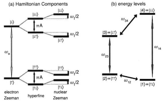
(a) Hamiltonian Components l w)
I0
~... I)...
.** 11T) ITT) ITT) i1•2 (b) energy levels 14)= III) 2 34 -I -\ __ 41, )u)IT)W
electron nuclearZeeman hyperfine Zeeman
Figure 2-1: Energy levels for le-1n spin system with isotropic hyperfine coupling: Part (a) shows the energy splittings due to individual terms of the le-1n isotropic Hamiltonian. The eigenstates and allowed transitions are shown in (b).
g-tensor in the cartesian lab frame, the electron Zeeman interaction is now Hez =
Bo (gzxSx + gzS, + gzzSz), which can be transformed to Hez = BogeffS. The
effec-tive g-factor is geff = + gy + zx gz2z and S' is aligned along the new quantization
axis, which is 5 = tan- 1 ••Z.) from the lab frame x-axis and 0 = tan- 1 = from
the lab frame z-axis. Assuming the nuclear chemical shift anisotropy is negligi-ble, the nuclear Zeeman term is aligned along the z-axis: Hnz = y,,Bolz. Since the electron Zeeman interaction is the dominant term, the eigenvalue of Sz is a good quantum number for the le-1n system. The hyperfine terms that do not commute with Sz do not result in first-order energy shifts of the eigenstates, so we neglect them here. For a completely isotropic hyperfine term, the total Hamiltonian is now
fully diagonal, with A = Azz:
Ho = CoeSz + anIz + 2mrA Szlz
We 0e 0 L=V 12 I1)=ITJ-W23 (2.7)
The resulting energy level structure is shown in Figure 2-1.
Now we consider the anisotropic part of the hyperfine interaction, AzxSzlx +
AzySzly, which can be simplified to a single term by an interaction frame
transfor-mation about the z axis with angle
p
= tan- 1 (1). The Hamiltonian is now block diagonal, with B = /Ax + AzY:H0 = WeSz + WanIz + 2nA Szlz + 27zB Szlx (2.8)
This Hamiltonian is diagonalized by the unitary transformation
Ud = e-i(OTEIy+OEe Iy) (2.9)
where El and El are the electron spin polarization operators 1 Ee = -1 + Sz (2.10) 2 1 Ee = 11 - Sz (2.11) - 2
and OT and 01 are the angles of the quantization axes in the electron spin-up and
spin-down manifolds, respectively:
= tan ( -B) (2.12)
2 A - --',
1 -B
1= )an (2.13)
01=2 tan-'
2
A+7A +
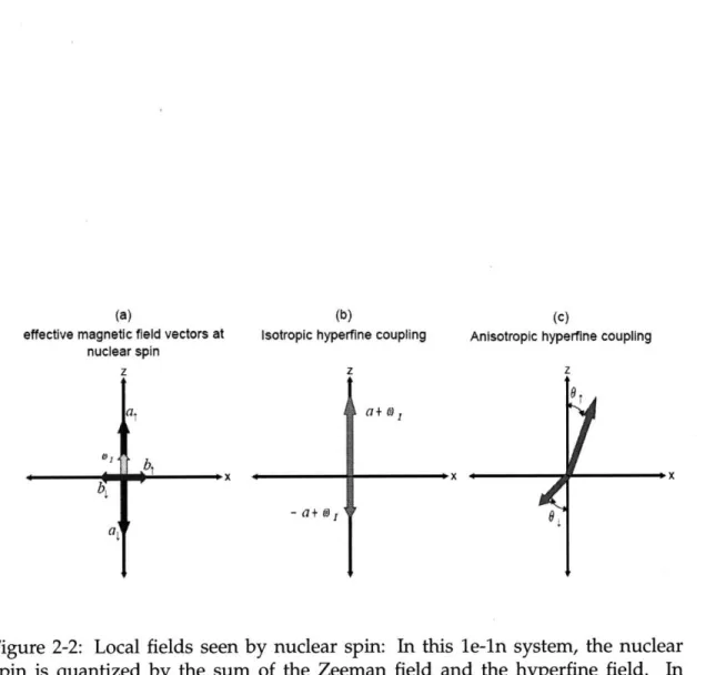
Figure 2-2 illustrates the magnetic field vectors seen by the nuclear spin in this le-in system and the resultant quantization axis. In this model the hyperfine coupling is comparable to the nuclear Zeeman term. Part (a) shows the components of the local field at the nuclear spin. As seen in (b), the nuclear spin is quantized along the z axis, but the local field magnitude depends on the electron spin state. As shown in (c), the anisotropic term quantizes the nuclear spin along different axes in the electron spin up and spin down manifolds. The system has the following
(a)
effective magnetic field vectors at nuclear spin
(b)
Isotropic hyperfine coupling
-a+ tj,
(c)
Anisotropic hyperfine coupling
Figure 2-2: Local fields seen by nuclear spin: In this le-ln system, the nuclear spin is quantized by the sum of the Zeeman field and the hyperfine field. In
(a) the individual components are shown: the Zeeman field w, aligns with the
z-axis, and the isotropic part a and anisotropic part b of the hyperfine field depend on the orientation of the electron. Part (b) shows purely isotropic coupling with
magnitude a. If the electron spin is along +2 (-2), the nuclear spin feels field a + wi
(-a + woj). Anisotropic hyperfine coupling (c) tilts the nuclear spin quantization
axis away from the z-axis, mixing the nuclear IT) and
11)
states in each electron spinmanifold.
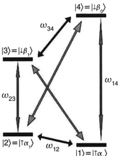
W34
13)= [10
w2 3
I1)=tTa0)
Figure 2-3: Energy levels for le-1n spin system with anisotropic hyperfine coupling: The nuclear spin eigenstates are now mixtures of the nuclear Zeeman states, and the mixtures are different in the electron manifolds. The nuclear spin with eigenstates Iao) and lal) in the the electron spin-up manifold is chosen as the qubit in this system. The light green arrows (color online) indicate that the forbidden transitions are now
allowed.
eigenvalues, and the energy level diagram is shown in Figure 2-3:
11)
=
IT
ao) =
IT)
0
(sin
OT IT)
+ cos OT
i1))
12) =
IT
a•) = IT)
®
(cos OT IT) - sin OT I))
13)
=
11 pi)
=
|1) ® (cos 0 IT)
-
sin 01
Ii))
14)
= 11Po)
=
11) ® (sin 0, IT) + cos
0
1I,))
(2.14) (2.15) (2.16) (2.17)
The following discussions of universal control and the use of the electron as a spin actuator are based on this model.
14)=110o
Ih'\ -,
2.2 Polarization of Nuclear Spins
We can now discuss the effect of AHF coupling on the nuclear polarization scheme outlined in Chapter 1. The SWAP operation in the eigenbasis of the electron-ith nuclear spin system can be used to transfer polarization:
UpTi = LISWAP(e, ni)Ud, = UdSWAP(e, ni). (2.18)
Udi = e-i(O•E iy+OEE-y) is the eigenbasis transformation described in equation 2.9. Note that the first transformation does nothing since the nuclear spin is in the
identity state. In this le-1n subsystem,
Pi = UPTiPeq UtTi (2.19)
=
(IT ao) (T aol
+
11 go)
(I
fo
I).
(2.20)
Projective measurement of the electron spin has a probability of 1 of yielding
2
the desired state IT ao) (T aol and a probability of 1 of yielding 1 f3o) (
13o.
Ifwe measure a spin down electron and apply a lab-frame n-pulse to return the electron to the ground state, we generate the following unwanted populations and
coherences, with q defined as the difference in quantization axis angles 0T - e,:
ldfie-isx77 Ut.
1
o0)
(3o1
U
e diS~u~iEe
® (cos2(j) 0ao)(aol0
+ Sin2(q)
ao) (aol
+ sin(q) cos(q) (lao) (al + Ila) (aol)) (2.21)
Applying a rotation by -, about ly to this state results in the desired state E' ® lao) (aol. Thus by using operators UpTL = UdtSWAP(e, ni) and Ug, = eihyle-isx" for the ith nuclear spin, we can use this process to polarize AHF-coupled nuclear spins.
Another polarization method would be to apply to both manifolds the trans-formation that diagonalizes the nuclear spin in the electron spin-up manifold. To
do this we rotate the nuclear spin about Iy in both manifolds by the angle - 0T after
applying the SWAP operation.
Uri = e-' UT Y (2.22)
UpTI, = USWAP(e, nli)Ur, = USWAP(e, ni) (2.23)
This operation puts the nuclear spin in the E' manifold in state lao) and the nuclear
spin in the Ee manifold in a state that transforms to lao) when Ug, = e-isx" is applied:
pi= UPTipeqUpTi (2.24)
S
IT
ao) (T aol + cos2(q) 1 P3o)(I /ol + sin2(q) 1. 1io) (, pol- sin(q) cos(q)
(
0f1
o)(4
PiJ + 1 fpi)(4 /o 1)
(2.25)In both of these cases, the UpT, andUg, operations affect only the ith nuclear spin, leaving the already polarized nuclear spins in their lao) states. We can choose which procedure is better suited for our spin system; it is likely the latter would be preferred, since the same Ugi can be used for each spin. Repeated N times, this
procedure produces the desired state ITe) 0 (lao))®N.
2.3 Nuclear Spin Relaxation
Using the le-1n system model, we can explore how nuclear spin relaxation differs between isotropically and anisotropically coupled systems. Starting with a sepa-rable initial state with no electron spin coherence, we look at how the nuclear spin
responds to the electron T1 process of random electron spin flips. In the isotropic
case, as shown in Figure 2-2 (b), the nuclear spin is quantized by a field along the z axis, but the magnitude of the field depends on whether the electron spin
is up or down. We describe the electron T1 process as a generalized amplitude
damping channel, in which random electron spin flips bring the spin to its equi-librium polarization [64]. These flips subject the nuclear spin to a field along 2 of randomly varying magnitude, causing the nuclear coherence to acquire a random
phase. Measurement of an ensemble of nuclear spins thus shows a decoherence rate linked to the electron T1. When the anisotropic part of the hyperfine interaction is added (Figure 2-2 (c)), the orientation of the nuclear spin quantization axis is also modulated by electron spin flips. The electron T1 processes in an AHF-coupled system thus cause variations in both the longitudinal and transverse local fields experienced by the nuclear spins. This leads to nuclear spin depolarization in addition to decoherence, linking both the nuclear T1 and T2 to the electron T1.
This simple model helps illuminate issues regarding the creation of viable qubits from these nuclear spins. In the isotropic case, a simple two-spin decoherence free subspace (DFS) can protect against the collective 2 noise caused by the electron T1 process [12, 26]. The anisotropy of the hyperfine interaction breaks the symmetry of the noise incident on the nuclear spins in this DFS. Thus the le-2n system does not provide us with a qubit resistant to electron T1 processes. In the le-3n system, a noiseless subspace that protects against all collective noise does exist [83, 33]. Further exploration of techniques to preserve nuclear spin qubits, including other logical encodings and dynamic decoupling, is needed.
2.4 Quantum Information Processing in Electron-Nuclear
Spin Systems
2.4.1 le-1n Spin Systems
Coherent control of ensembles of hyperfine-coupled spins has been demonstrated in a few simple systems. Using magnetic resonance techniques, Mehring has shown entangling operations between an electron and nuclear spin in two systems: a malonic acid free radical [56] and a nitrogen atom encased in C60 [57, 75]. In both of these systems, he used electron-nuclear double resonance (ENDOR) to generate Bell states consisting of one electron qubit and one nuclear qubit. The basis states
2-1). The nuclear spin polarization operators are 1 En = 2 + Iz (2.26) 1 En = 1 I- Iz. (2.27) 2
Starting with the thermal equilibrium state Po, a pseudopure state is created by a combination of unitary and nonunitary operations:
Po = -Sz = -SzE+ - SzE n (2.28)
cos-1 (-'))SxE_ T2e decay 1 2 4
3 -SzEn +
+
"S3
zE- = -Sz3
- -Sz2 z (2.29)3
S)E+Ix T2n decay > 2-(-Sz + Iz - Szlz)
(2.30) 3
This last term, after discarding the identity part, is the pseudo-pure state IT). All four pseudo-pure basis states can be created using similar sequences. Selective electron and nuclear spin pulses are used to generate the singlet state:
,T 2)EI _ 2)S - •
it)
•(T)
1
+i]T))
--(IT)
+14))
(2.31)Mehring showed that similar sequences can be used to generate all 4 Bell states. He
also performed this experiment on an 15N atom encased in a C
60 buckyball, which
has a spin-3/2 electron coupled to a spin-1/2 nucleus. The Bell states were generated on a 4-level subsystem. In both of these experiments, it was necessary to use three control fields-one selective electron spin excitation and two selective nuclear spin excitations. Using the electron spin actuator, it should be possible to precisely create these entangled states with only modulated electron spin excitations.
2.4.2 le-Nn Spin Systems
We are also exploring spin systems in which a single paramagnetic center is coupled to more than one nuclear spin. The same malonic acid radical used in the above
experiments has been shown to have a strongly anisotropic hyperfine coupling
with a 13C labeled (spin-!) methylene carbon [53]. This sample would allow us
to perform experiments such as the demonstration of a nuclear-nuclear gate using an electron spin actuator and a study of relaxation in two-spin decoherence free subspaces. A protected subspace in a le-3n system can potentially be demonstrated on organic crystal radicals strongly coupled to three protons[39]. However, as we have experienced in our malonic acid experiments, it is difficult to make high-quality single crystals from these organic compounds.
Paramagnetic defects in inorganic crystals could also be viable systems for spin actuators. Defects and dopants in calcium fluoride crystals that exhibit localized paramagnetic centers have been studied extensively with ESR and NMR. For ex-ample, Mehring studied the spin of a cerium dopant occupying a calcium site that couples strongly to 9 fluorine nuclear spins [31]. These systems are promising be-cause the electron spin is highly localized and fabrication of high-quality crystals is relatively straightforward.
Mehring's S-bus experiment used electron-nuclear double resonance (ENDOR) to perform operations on a single electron coupled to several nuclear spins in a
calcium fluoride crystal [58]. Only the nuclear spin states of one electron
mani-fold were used as qubits. Starting from a thermal equilibrium state in which the nuclear spins are essentially unpolarized and the electron spins have a Boltzmann distribution, pulses on the electron spin transitions were used to prepare a nuclear spin register. NMR pulses were then used to perform gates on the nuclear spins, followed by electron spin pulses to transfer the desired nuclear information back to an electron polarization for readout.
The nitrogen-vacancy center in diamond is another promising spin system for QIP. This center occurs when a substitutional nitrogen and a vacancy occupy neigh-boring sites in the diamond lattice. This results in a spin triplet ground state with a long coherence time, even at room temperature. An optical transition of the N-V center can be used to pump the system into its ground state and to measure the state of a single center. Lukin's group studied the dynamics of N-V centers coupled
to 13C nuclear spins [15] and demonstrated that this e-n system could be used as
a quantum register [20]. The Awschalom group studied N-V centers coupled to electrons of substitutional nitrogen spins, suggesting the possibility of a nitrogen spin chain between N-V centers [30].
Electron-nuclear spin systems in semiconductors are used in a wide variety of quantum computer implementations. Kane's silicon-based quantum computer [41] and hydrogenic quantum computer [77] proposals both utilize phosphorus-doped silicon. In his silicon-based quantum computer proposal, control of individual nuclear spin qubits is achieved using nuclear magnetic resonance combined with the ability to manipulate the hyperfine interaction by using electrical gates to shift the electron's wavefunction. Interactions between qubits are controlled by using voltage gates to regulate the overlap of wavefunctions of neighboring electrons. In Kane's hydrogenic spin quantum computer, which is also silicon-based, the qubit exists in a subspace of a le-1n spin system. Single qubit operations are performed with electrical gates and external magnetic fields, and qubit-qubit interactions are achieved by shuttling electrons from one nuclear spin to another. In both of these proposals, with isotopic engineering of silicon, it is conceivable that each localized
electron could act as a spin actuator controlling a cluster of spin-1/2 29Si spins.
Quantum dots-semiconductor structures which spatially confine small num-bers of electrons-are also promsing candidates for quantum information proces-sors [49, 66, 44]. Research in quantum dots has not yet demonstrated sufficient electron localization to be used with this implementation of spin actuator control of nuclear spins. Single-spin measurements in quantum dots and studies of elec-trical gate control of electron g-factors [84] and nuclear spin cooling in quantum dots [16, 81], however, do link to our proposed quantum information processor.
Superconducting circuit qubits are also built on semiconductors, and interact with substrate spins. Though nuclear spins are typically regarded as sources of decoherence [65, 71, 21], the possibility of coherent coupling between nuclear spins and superconducting qubits can be considered. These engineered systems offer some promise of scalability.
Chapter 3
Achieving Universal Control of Spin
Systems
This chapter gives a simple argument showing that universal control of anisotropic hyperfine coupled electron-nuclear spin systems can be achieved with only elec-tron spin excitations. We then discuss the use of an optimal control algorithm to precisely generate unitary operations on the coupled spin system, and the system model parameters needed for accurate control.
3.1
Universality of Electron Spin Actuator Control
Control of an electron spin in an external magnetic field (Bo = B0o) is achieved
by applying transverse fields (BI = B1x + B1,9) at frequencies resonant with the
electron spin transitions. The Hamiltonian describing the interaction of the spin with this applied field is
H1 = hgeBi(t) -S (3.1)
= -geB1(t) (Sx cos(Comwt + q(t)) + Sy sin (comwt + q(t)) (3.2)
At a fixed transmitter frequency Wrmw, we have two degrees of freedom that we can
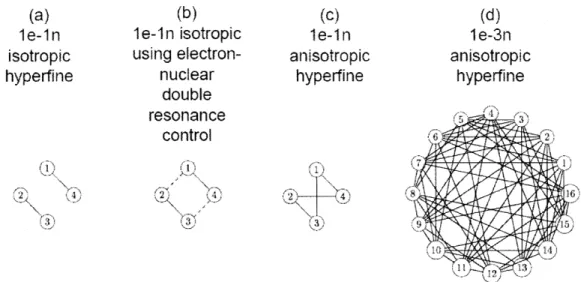
(b) le-1n isotropic using electron-nuclear double resonance control 7- ,
(c)
1le-1 n anisotropic hyperfine (.i' )Figure 3-1: Universal control of le-Nn system with electron spin excitations. Solid black edges link nodes which are connected by the operator Sx; dashed red edges link nodes connected by Ix. This figure shows that in a system with isotropic hy-perfine coupling, the states cannot be connected with only electron spin excitations (a) and require nuclear spin excitations to be fully connected (b). AHF-coupled spins allow forbidden transitions to be addressed, fully connecting the states (c). Universal control using only electron spin excitations is possible in systems with N nuclear spins individually coupled to the electron spin via the AHF interaction
(d).
experiments discussed in this thesis, 0(t) = 0 and spin actuator control is achieved using only amplitude modulations of Sx:
H1 = -geBi (t)Sx cos (Wmwt) = o) (t)Sx cos (wmwt)
In Figure 3-1 we use a simple graphical argument to show that we can achieve universal control of an AHF-coupled spin system by inducing only electron spin transitions. The nodes of this graph are the eigenstates of the spin system, as described in the previous chapter. A solid black edge connects nodes m and n for which the term (m ISx| n) # 0, and the dashed red edge connects nodes for which
(m n) tIx s 0. c
In the isotropic le-1n case (a), an electron spin transition Sx connects state 11) to
(a) le-1n isotropic hyperfine \~- Yi (d) l e-3n anisotropic hyperfine (3.3)
14)
and 12) to13).
In order to address all four states, at least three transitions need to be addressed. The isotropically-coupled system requires direct excitation of the nuclear transitions, as shown in (b), for universal control.The addition of anisotropic hyperfine coupling (c) allows the Sx operator to address all 4 electron transitions. These matrix elements indicate how strongly
these terms are addressed, assuming an excitation bandwidth larger than coW, A,
and B (as defined in Chapter 2):
(1
ISxI
4) = cos(0T - 0Q) (3.4)(1
ISx|
3) = sin(01 - 0Q) (3.5)(2 Sxl 3) = cos(A - OT) (3.6)
(2 |SKi 4) = sin(0Q - 0,) (3.7)
The "forbidden" transitions are strictly forbidden when OT = 0; the forbidden
and allowed transitions are equal in magnitude when |OT-011 = 71/4. This argument for universality scales to larger numbers of nuclear spins, provided each nuclear spin is anisotropically coupled to the electron, as shown in (d) for three nuclear spins. This requirement hints at an upper limit to the number of nuclear spins that can be coupled to a single electron spin actuator: Degenerate transitions cause a loss of addressability. The maximum number of spins is a function of electron wavefunction, hyperfine strength, linewidth, and the ability to effectively excite the forbidden transitions.
3.2 Pulse Engineering: Using Optimal Control to
Per-form Precise Unitary Operations
The use of the electron spin as an actuator allows us to improve the efficiency of control of nuclear spin qubit states: Because the nutation frequency of a spin is proportional to its magnetic moment, applying control fields directly to the
nu-14)= [-3o)
13)=
mm
12) =
Tot)-I 1)= Tot)-ITO)
Figure 3-2: Spin actuator control: With only a modulated excitation on a single transition (wavy blue line), we can perform a precise unitary operation (e.g., n)sx, red arrows) that excites all electron transitions.
clear spins requires longer pulse times and more power than addressing only the electron spin. Control is also simplified, since we can apply any unitary opera-tion on the le-1n system while sitting on a single transmitter frequency (Figure 3-2). To take advantage of the universality provided by the AHF interaction, we used an optimal control algorithm to find pulse sequences implementable by our spectrometer. The Gradient Ascent Pulse Engineering (GRAPE) algorithm, devel-oped by Khaneja [42], finds pulses that implement the desired unitary operations with high fidelity. This gradient-based pulse optimization scheme represents an improvement over previous methods with a substantially more efficient method to
calculate derivatives of performance functions.
We seek to apply a desired unitary operation Uw,,ant by applying a set of m
control Hamiltonians Hk to the spin system with natural Hamiltonian H0. The
control sequence is discretized such that the propagator during time step j is
Uj = e-iAt(Ho+Eki= uk(j)Hk) (3.8)
A control sequence of N steps gives the total propagator
Utotal = UNUN-1...U2U1. (3.9)
j
The control Hamiltonian amplitudes Uk define the modulation of the microwave
excitation-they are the knobs we turn to achieve Uwant. We start with a random
sequence of Uk's and calculate a goodness function P from the sequence. In this
case we use the fidelity squared
( = (UwantlUtotal) 2 ((3.10)
(3.11) = (UwantIUNUN-l...U2U (U1 U2...UN-1 UN Uwant).
Using the fact that the inner product is invariant under cyclic permutation,
(UwantlUtotal) = (W U +2..." Uwant IUjUj-...U2U1 . (3.12)
We give the bra and ket of equation 3.12 the labels Pj and Xj, respectively:
Pj = (,
+2
U ant
Xj) =
ujU
j-1...
U2U
)
(3.13) (3.14)
Using the matrix exponential formula
d X(t)10=
dX
1i
e(1-a)x(t)
X eaX(t)dct
edt
we calculate the derivative, to first order, of the propagator Uj with respect to the amplitude Uk: =Uj -iAtHkUj (3.16) 6Uk with
-
10A
t Hk = - Uj(c)HkUj(-T)dTUj(1
)
= e-iT(Ho+EY=l uk(j)Hk)(3.17) (3.18)
For small timesteps, Hk ; Hk and we can calculate the gradient of the goodness (3.15)
Figure 3-3: GRadient Ascent Pulse Engineering (GRAPE): The pulse is comprised of N steps of length At. The parameter uk is the amplitude of control Hamiltonian
Hk. Each iteration of the algorithm calculates the goodness of the pulse and a
gradient used to adjust Uk for each timestep in the pulse.
function:
=6 -(PjlXj) (iAtHkXjPj) - (PjliAtHkXj) (XjlPj)
6 Uk
= -2Re ((PliAtHkXj) (X;iP)) (3.19)
A threshold is set for the goodness function, and if it is not met, the control param-eters Uk are adjusted according to the calculated gradient:
&I>
uk(j) - Uk(j) + e (3.20)
6Uk(j)
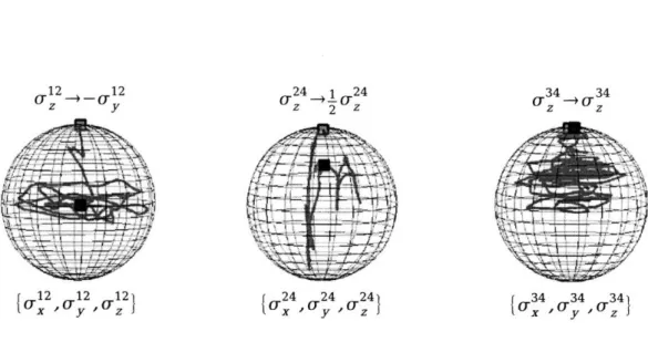
This sequence, as illustrated in Figure 3-3 from [42], is repeated until a set of parameters Uk generates a propagator with sufficient fidelity. To illustrate the evolution of the spin states during application of a GRAPE pulse, Figure 3-4 shows the evolution on the Bloch sphere of fictitious spins of a le-1n system during
application of a )12 pulse between two eigenstates.
We see that the pulse reliably executes the desired operation, and the evolution during the pulse is complex: The trajectories of the fictitious spins change dras-tically and frequently, and can traverse a large range of the Bloch sphere. This modulation averages out unwanted evolution in the system, as shown with the strongly modulating pulses used in liquid-state NMR quantum computing studies [25].
12 12 (.24 -io724
z y z 2 Z z
-4
O 2 12 12 24 24 24 34 34 34
Figure 3-4: Evolution of spin during a )12 pulse: Bloch sphere plots of the trajectoryn•2 puse
of fictitious spins during application of a ,x pulse.
3.3 Full System Model
3.3.1
Quality Factor of Resonator
Magnetic resonance experiments-especially those in which weak measurements are performed on an ensemble of spins-typically employ resonators to amplify the coupling between the spins and the excitation/detection circuitry. At the resonance frequency, the oscillating magnetic field applied to the spins and the sensitivity of detection of the precessing spins are enhanced. The quality factor (Q), defined as
2n times the ratio of the power stored in the resonator to the power dissipated in
one oscillation cycle, quantifies the enhancement due to the resonator. To see how this affects the control of the system with GRAPE pulses, we recall the relation
of the quality factor to the resonator bandwidth:
Q
= f, wherefo
is thereso-nance frequency and Af is the bandwidth. The resonator filters the GRAPE pulse, attenuating modulation frequencies that exceed the bandwidth of the resonator. Simulations show that this effect significantly degrades the fidelity of the GRAPE pulses; the experimental results reported in this thesis also indicate this. Subse-quently, our GRAPE code has been modified to search for modulation sequences
that account for this filtering, allowing us to find high-fidelity pulses while using
resonators with relatively high Q for pulsed ESR
Q
> 200 [3].3.3.2 Inhomogeneity of Magnetic Fields
The simple Hamiltonian presented in Chapter 2 does not account for
inhomo-geneities in B0 and B1. Challeges in designing fields for quantum control have
been discussed by Rabitz [10, 68]. In liquid state NMR experiments, open-loop
feedback and pulses robust against B1 inhomogeneity have been demonstrated
[8]. We assume that all the spins in the ensemble experience the same magnetic fields, but experimentally there are often slight variations across the sample. Spa-tial static field inhomogeneity can be caused by magnet nonuniformity, sample
shape effects, or the presence of magnetic materials in the probe. Spatial B1 field
variations are largely caused by the resonator. The solenoidal fields of loop-gap resonators and bridged-loop-gap resonators (cf. Chapter 4) are quite uniform, but imperfections in fabrication, sample location and size, and interactions between
the sample holder or the sample with the fringing electric fields can lead to B1
inhomogeneity. GRAPE can find pulses robust against these inhomogeneities, but an accurate model is necessary.
3.3.3
Crystal Quality
High quality single crystals are necessary for these spin ensemble experiments. Ide-ally, all electron-nuclear spin systems in the ensemble have identical Hamiltonians; experimentally, the Hamiltonians are often altered by impurities, twinning, and other crystal defects. Organic crystals, such as the malonic acid used in these ex-periments, often trap water during crystallization. This can alter the environment of nearby spins and cause localized heating when oscillating fields are applied.
3.3.4 Spin System Hamiltonian
When searching for pulses, we have considered only the largest components of
the Hamiltonian-Hez, H1z, and HHF-and considered the weaker terms to be
negligible. The GRAPE code thus finds pulses that perform unitaries on a certain Hamiltonian, often neglecting the full linewidth of the electron transition. In malonic acid, for example, the 5 gauss ESR linewidth is caused by interactions with both the nearby nuclear spins and the more distant matrix protons [47]. Without using a good model of this, the GRAPE pulse will operate properly only on a subset of spins.
Chapter 4
Spectrometer Design
Pulsed ESR and ENDOR have been used for spectroscopic applications for more than 40 years [59, 60]. The available commercial pulsed ESR systems, however, do not provide the flexibility we need to implement the optimal control pulses. This chapter discusses the key components of our current and future spectrometer designs.
4.1 Pulsed ESR Spectrometer: Version 1
4.1.1
Design Specifications
Conducting pulsed ESR experiments at X-band (8-12 GHz) allows us to achieve ac-ceptable polarization and sensitivity without making the implementation of precise control prohibitively expensive or difficult. More importantly for our experiment, it makes the nuclear Zeeman term comparable to the hyperfine term,
maximiz-ing the magnitude of the forbidden transitions. With the B0 field for an X-band
electron spin transition, the nuclear Zeeman term is on the order of 10 MHz. The strength of the hyperfine coupling can range from tens of kiloHertz to hundreds of megaHertz for nearby spins. Using the GRAPE algorithm to find spin actuator
control sequences, we see that a B1 smaller than the nuclear Zeeman and hyperfine
control, but this is often costly to achieve. For the malonic acid radical used in our experiments, we could find sub-microsecond pulses for all desired unitaries with a
B1 of 4 MHz. Another requirement is that our sensitivity needs to be high enough
to measure the signal from a sparse ensemble of spins at cryogenic temperatures. If the T, is sufficiently brief, we can signal average to improve the signal to noise ratio (SNR). Reliable averaging requires the absence of low-frequency noise and drifts in the spectrometer.
4.1.2 Probehead
Resonator
The microwave fields are contained in a simple loop-gap resonator (LGR), intro-duced by Froncisz and Hyde [27, 54, 55]. The LGR, a lumped-element resonator with an inductance and capacitance determined by its geometry, has several prop-erties well-suited for pulsed ESR: small volume (large filling factor), uniform mag-netic field, and low quality factor (short ringdown time, large bandwidth). For this spectrometer we designed a two-gap one-loop resonator, a simple hollow conduc-tive cylinder with two slits cut along the length of the cylinder (Figure 4-1). We can approximate the inductance L as that of a solenoid and the capacitance C of the gaps as that of parallel plate capacitors in series (r is the radius, Z is the length of the LGR and the capacitor plates, W is the capacitor plate width, t is the gap size,
and n is the number of gaps):
/.o0r2 L - 2 (4.1)
Z
eWZ C = (4.2) ntThe resonant frequency is thus
1 1_ nt
fo
C 2 eor2W (4.3)z
Figure 4-1: Loop-gap resonator and coupling loop: The resonator was fabricated by cutting two gaps out of oxygen-free high-conductivity copper and mounting it on the inside of a quartz tube. Inductive coupling to the microwave amplifier and receiver was provided by a loop formed from the center conductor of a semi-rigid coaxial cable.
More accurate approximations of the resonant frequency have been reported [27,54,55]. The maximum microwave field strength at the center of the resonator is
given in [76], where QL is the loaded quality factor of the resonator, P is the incident
power, and Vc is the effective volume of the resonator:
S2QLPYO
B1 = •Vfo (4.4)
The sensitivity S of the resonator depends on the same parameters:
Q L 02
S oc VT (4.5)
Vc
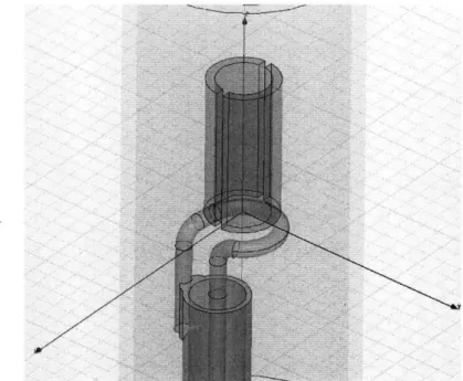
At the resonance frequency the fields in the loop-gap resonator are solenoidal. The current flows along the circumference of the cylinder, and the magnetic field is directed along the axis of the cylinder. Figure 4-2 shows a vector plot of the magnetic field at resonance, generated by Ansoft HFSS, a commercial finite element method
H Field[A/m] 5 2599e+02 4.9265e+02 4.5981e*02 4 ,2696e+02 3,9412e+02 3. 6i2e+02 3 2899e+02 2.9559e+02 2.6275e-02 2.2991e+02 1. 9707e+02 1.6922e402 1.3138e+-02 9.,8540e+01 6 5698e+01 3. 2855e+01 i.2785e-02
Figure 4-2: Magnetic field vectors in LGR: This vector plot of the magnetic field along the center axis of the LGR shows the desired mode at resonance. The field is directed along the z-axis, and is at a maximum at the center of the resonator. The size of the arrows scale with the magnitude of the field vector at the origin of the arrow (color online).
(FEM) software package. The size of each arrow is proportional to the magnitude of the magnetic field vector at the origin of the arrow. The simulation shows the expected field, a solenoidal field with a maximum at the center of the resonator.
Our LGR was fabricated from oxygen-free high conductivity copper mounted with cyanoacrylate glue in a quartz tube. With a diameter of 3 mm, gap sizes of about 0.6 mm, and length 8 mm, the LGR exhibited the desired loaded resonance of 11 GHz. The resonator is placed inside a 12.75 mm diameter microwave shield also made from copper tube. The loaded quality factor of the resonator is measured
to be approximately 250, and the maximum B1 field measured was 2.5 Gauss (7
Coupling
Inductive coupling to the resonator was accomplished by terminating a semi-rigid coaxial cable with a loop formed out of the coax's center conductor, as drawn in Figure 4-1. Coupling via mutual inductance is one of a variety of coupling methods for loop-gap resonators, and the most commonly used in the literature [70]. Optimal power transfer to the LGR, as with all transmission line systems, requires that the impedance of the transmission line matches that of the load (the loop termination-resonator system). While many researchers overcouple their termination-resonators to lower
the Q (and thus the ringdown time), we chose critical coupling to maximize the B1
field and because the ringdown time does not limit this experiment. The critical coupling condition is met when the resonator is at a certain angular orientation and distance relative to the loop. The angular orientation is adjusted prior to closing and pumping down the spectrometer. Using a motion stage and berylium-copper bellows, we are able to control the distance between the loop and resonator while under vacuum. This is necessary to optimize matching to the resonator, as the stainless steel cold finger shrinks by about 3mm when cooled from room
temperature to liquid nitrogen or helium temperatures [22].
Characterization of resonators is performed by measuring the reflected power from the coaxial cable with either a network analyzer or microwave detector diode. Access to a network analyzer was limited, so determination of the resonance of the probe was often performed by systematically varying the matching and using a diode to measure the reflected power vs. frequency. This was necessary be-cause absorption peaks arising from the copper shield and the transmission line configuration often obscured the resonance peak from the resonator. Microwave resonances arising from the box containing the probe were attenuated by inserting dissipative material into the free space of the box containing the probehead. We found that the anti-static bags used to package sensitive electronic components worked well for this purpose.