Model Transformations from a Data Parallel Formalism towards Synchronous Languages
47
0
0
Texte intégral
(2) INSTITUT NATIONAL DE RECHERCHE EN INFORMATIQUE ET EN AUTOMATIQUE. Model Transformations from a Data Parallel Formalism towards Synchronous Languages Huafeng Yu — Abdoulaye Gamatié — Éric Rutten — Jean-Luc Dekeyser. N° 6291 September 2007. SN 0249-6399. apport de recherche. ISRN INRIA/RR--6291--FR+ENG. Thème COM.
(3)
(4) Model Transformations from a Data Parallel Formalism towards Synchronous Languages ´ Rutten‡ , Jean-Luc Dekeyser§ Huafeng Yu∗ , Abdoulaye Gamati´e† , Eric Th`eme COM — Syst`emes communicants Projets DaRT, Pop Art Rapport de recherche n 6291 — September 2007 — 43 pages. Abstract: The increasing complexity of embedded system designs calls for high-level specification formalisms and for automated transformations towards lower-level descriptions. In this report, a metamodel and a transformation chain are defined from a high-level modeling framework, Gaspard, for data-parallel systems towards a formalism of synchronous equations. These equations are translated in synchronous data-flow languages, such as Lustre, Lucid synchrone and Signal, which provide designers with formal techniques and tools for validation. In order to benefit from the methodological advantages of re-usability and platform-independence, a Model-Driven Engineering approach is applied. Key-words: Intensive signal processing, data-parallel, Gaspard, Array-OL, synchronous approach, MDE, model transformations. ∗ † ‡ §. [email protected] [email protected] [email protected] [email protected]. Unité de recherche INRIA Futurs Parc Club Orsay Université, ZAC des Vignes, 4, rue Jacques Monod, 91893 ORSAY Cedex (France) Téléphone : +33 1 72 92 59 00 — Télécopie : +33 1 60 19 66 08.
(5) Transformation de mod` eles ` a partir d’un formalisme ` a parall´ elisme de donn´ ees vers des langages synchrones R´ esum´ e : La complexit´e croissante de la conception des syst`emes embarqu´es entraˆıne un besoin de formalismes de sp´ecifications de haut niveau ainsi que des transformations automatis´ees vers des descriptions de plus bas niveau. Dans ce rapport, un m´etamod`ele et une chaˆıne de transformation sont d´efinis a ` partir d’un cadre de mod´elisation de haut niveau, Gaspard, pour des syst`emes avec du parall´elisme de donn´ees, vers un formalisme d’´equations synchrones. Ces ´equations sont ensuite traduites dans les languages synchrones flot de donn´ees, tels que Lustre, Lucid synchrone et Signal, qui offrent aux concepteurs des techniques et outils de validation. Afin de b´en´eficier des avantages m´ethodologiques de la r´eutilisabilit´e et de l’ind´ependance vis-` a-vis de toute plate-forme, une approche d’Ing´enierie Dirig´ee par les Mod`eles (IDM) est appliqu´ee. Mots-cl´ es : Traitement intensif du signal, parall´elisme de donn´ees, Gaspard, Array-OL, approche synchrone, IDM, transformations de mod`eles.
(6) Model Transformations from a Data Parallel Formalism towards Synchronous Languages 3. Contents 1 Context and motivation 1.1 MDE and data-parallel applications . . . . . . . . . . . 1.2 The Gaspard methodology for data-parallel computing 1.3 Motivation: connecting Gaspard to validation tools . . 1.4 Outline . . . . . . . . . . . . . . . . . . . . . . . . . . .. . . . .. . . . .. . . . .. . . . .. . . . .. . . . .. . . . .. . . . .. . . . .. . . . .. . . . .. . . . .. 2 Background and proposed approach 2.1 Data-parallel application design: Gaspard 2.1.1 An overview of Gaspard . . . . . . 2.1.2 The Gaspard metamodel . . . . . . 2.1.3 A simple example . . . . . . . . . . 2.2 The synchronous approach . . . . . . . . . . 2.3 The proposed approach . . . . . . . . . . .. . . . . . .. . . . . . .. . . . . . .. . . . . . .. . . . . . .. . . . . . .. . . . . . .. . . . . . .. . . . . . .. . . . . . .. . . . . . .. . . . . . .. . . . . . .. . . . . . .. . . . . . .. . . . . . .. . . . . . .. . . . . . .. 7 . 7 . 7 . 8 . 9 . 10 . 11. 3 A synchronous equational 3.1 Signal . . . . . . . . . . 3.2 Equation . . . . . . . . 3.3 Node . . . . . . . . . . . 3.4 Module . . . . . . . . .. . . . .. . . . .. . . . .. . . . .. . . . .. . . . .. . . . .. . . . .. . . . .. . . . .. . . . .. . . . .. . . . .. . . . .. . . . .. . . . .. . . . .. . . . .. . . . .. 11 12 13 13 13. 4 Model transformations 4.1 From Gaspard model to synchronous equational model 4.1.1 Transformation rules . . . . . . . . . . . . . . . . 4.1.2 Illustration of a rule model . . . . . . . . . . . . 4.1.3 Implementation of a transformation chain . . . . 4.2 Synchronous code generation from the equational model 4.3 Application examples . . . . . . . . . . . . . . . . . . . . 4.3.1 Matrix average . . . . . . . . . . . . . . . . . . . 4.3.2 Image downscaling . . . . . . . . . . . . . . . . .. . . . . . . . .. . . . . . . . .. . . . . . . . .. . . . . . . . .. . . . . . . . .. . . . . . . . .. . . . . . . . .. . . . . . . . .. . . . . . . . .. . . . . . . . .. . . . . . . . .. . . . . . . . .. 13 15 15 18 21 22 22 23 24. metamodel . . . . . . . . . . . . . . . . . . . . . . . . . . . . . . . .. . . . .. 5 Design validation based on synchronous 5.1 General issues . . . . . . . . . . . . . . . 5.2 Deadlock detection . . . . . . . . . . . . 5.3 Simulation . . . . . . . . . . . . . . . . .. . . . .. . . . .. 4 4 5 6 7. languages 26 . . . . . . . . . . . . . . . . . . . . . 26 . . . . . . . . . . . . . . . . . . . . . 28 . . . . . . . . . . . . . . . . . . . . . 29. 6 Related works. 30. 7 Conclusions and perspectives. 31. A Generated code for the downscaler. 35. RR n 6291.
(7) 4. 1 1.1. Yu & Gamati´e & Rutten & Dekeyser. Context and motivation MDE and data-parallel applications. Data-parallel applications, such as mobile multimedia processing, high-definition TV and radar/sonar signal processing, play an increasingly important role in embedded systems. Parallel massive data processing is a key feature in these applications. Unlike general parallel applications which focus on the code parallelization and their communications, dataparallel applications pay more attention to data distribution and their access. The data manipulated in these applications are generally in multidimensional data structure, such as multidimensional arrays. And regularly repeated computations manipulate associated small data blocks, which are called tiles and can be also multidimensional, from the input data. But these applications become increasingly more complex following the trend of integration of more and more various functionalities into one single system and/or into one single chip. As a result, their design, implementation and validation turn out to be dramatically more complicated and difficult. Furthermore, the increasing system complexity leads to the productivity problem that becomes a great constraint for the developments. Hence, more efficient design methods, including modeling, implementation and validation methods are highly needed. Nowadays, among intensive research activities to address such problems, Model-Driven Engineering (MDE) [34, 28] based methods should be mentioned. Model is the key concept in MDE, which is greatly influenced by the concept of abstraction. It enables to represent the system with an accepted level of abstraction, i.e., all unnecessary details of the system are removed for the sake of simplicity of modeling, analysis, etc., whereas the obtained models is usable. Another key point of MDE is to enable the transformations between models. These model transformations are not only from high-abstraction level into lower ones, but from models of one domain into models of other domains. One of the best known MDE initiative is Model-Driven Architecture (MDA) [27], which is proposed by OMG (Object Management Group) [30]. According to MDA, two types of model are distinguished following the abstraction level: Platform-Independent Models (PIM) and Platform-Specific Models (PSM). The former generally represents the system functional requirements, and the PSM always involves implementation concerns. For example, a PSM can be an executable model itself, or be used to generate certain domain-specific source code, etc.. Transformation specifications are also proposed by OMG to bridge these two types of model. UML is always taken as the visual modeling language in MDE. It is supported by many visual modeling environments and tools now. MDE brings several advantages: well-defined modeling specifications lead to rapid design as well as concise and clear documentation; and their automated transformations offer the opportunity to simplify the code generation in consideration of their correctness; finally, the re-usability and modularity of their models and Intellectual Properties (IPs) make the development of these applications more efficient and rapid.. INRIA.
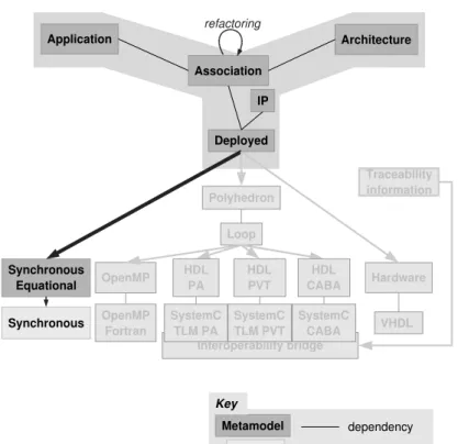
(8) Model Transformations from a Data Parallel Formalism towards Synchronous Languages 5. 1.2. The Gaspard methodology for data-parallel computing. Gaspard [17] is a MDE based development environment and methodology for the design of data-parallel applications. It proposes concepts, which feature high level data-parallel concepts, data flow and control flow mixing, hierarchical and repetitive application and architecture models, etc. The inherent data-parallel description of Gaspard was adopted by MARTE (Modeling and Analysis of Real-Time and Embedded systems) [33], which is an OMG standard proposal for the modeling and analysis of real-time embedded systems. One of the important feature of Gaspard is its software/hardware co-modeling and model transformations. More precisely, it enables to model software applications, hardware architectures, their association and IP deployment through predefined metamodel in a unique modeling environment. This modeling stays in a high abstraction level and is usually platform independent. Gaspard enables as well transformations from these models to lower level models, which are involved in the execution, synthesis and validation issues.. Figure 1: Y-chart according to Gaspard.. RR n 6291.
(9) 6. Yu & Gamati´e & Rutten & Dekeyser. This metamodel is partially based on the concept of the Y-chart (see Fig. 1 and [17]). Models for application and hardware architecture are defined separately. Then, application models can be mapped on architecture models. The obtained models are linked to software or hardware IPs during the deployment phase. All these models are platform-independent, i.e., they are not associated with an execution, simulation, validation or synthesis technology. Model transformations are performed from deployed models to specific languages (synchronous languages and others, which are not detailed in this paper and are shadowed in Fig. 1, such as HPF, SystemC and VHDL). These characteristics of Gaspard make it easier to reduce the complexity of system design. In the following, we briefly present the main features of the Gaspard metamodel: Application focuses on the description of data parallelism and data dependencies between application components. These components and dependencies completely describe the functional behavior. Application components mainly manipulate multidimensional arrays, with a possible infinite dimension to represent time. Data-parallel constructs, such as ”tiler” (see [6]) has been included in this metamodel, which offers the opportunity of expressing the regular multidimensional data access. This metamodel defines as well task repetition in correspondence to data-parallelism. The tasks are either atomic computations (elementary task) on arrays or composed tasks (hierarchical task). Architecture specifies the hardware architecture at a high abstraction level. It enables to dimension hardware resources. A mechanism similar to the one used in application enables to specify repetitive architecture in a compact way as the increasing popularity of these kinds of regular parallel computation units in hardware. Association. allows one to express how the application is projected on the hardware architecture, i.e., which hardware component executes which functionality. One particularity of this metamodel is to consider the mapping as well as the parallelism both in the application and architecture. Deployment (represented by the box tagged as ”Deployed” in Fig. 1) enables to chose a specific target platform for code generation from Gaspard models. This is achieved by importing IPs in which no implementation details are provided except their interfaces, information about compilation and their inter-communications.. 1.3. Motivation: connecting Gaspard to validation tools. In embedded system design, the top-down approach, which goes from the high abstraction level to low implementation levels, is well adopted. Furthermore, the reliability of the system is always a significant issue, which requires the correctness of the design and implementation. On one side, the automatic transformation from the system specification to implementation details reduces the error occurrences caused by the manual coding. On the other side, the. INRIA.
(10) Model Transformations from a Data Parallel Formalism towards Synchronous Languages 7. design correctness verification at the original high abstraction level is as well necessary as the high level verification helps to reduce the system design complexity and to avoid to handle too many implementation details at the beginning development stage. Gaspard models are dedicated to the co-modeling of data-parallel applications at high abstraction level with the help of the UML visual modeling language. However UML suffers from the lack of formal semantics, which is necessary for the formal verification and validation of the system design. Thus, a map from these models on formal methods is needed. Synchronous languages are well known for their formal aspects and their richness in terms of tools for verification, analysis and code distribution. Therefore, the connection of these two technologies is encouraged because it offers the opportunity to benefit from the capabilities of Gaspard in the specification of data-parallelism and also from the power of formal aspects of synchronous languages. This report presents how MDE transformations contribute to bridge the two technologies through crossing the different abstraction levels from Gaspard to synchronous languages (Lustre [13] is considered here for illustration).. 1.4. Outline. In section 2, a brief introduction to the background and our proposed approach is given. The background includes the data-parallelism, particularly Gaspard co-modeling environment, and synchronous languages, particularly Lustre. It is followed by the proposed synchronous equational metamodel in section 3. This metamodel is dedicated to the specification of data-parallelism for synchronous languages. Model transformations and some implementation examples are then detailed in section 4. These transformations are regrouped into a transformation chain and some examples of matrix and image processing are showed. After, some general validation discussions and implemented examples (section 5) are presented. Related works are discovered in the section 6. Finally the conclusions and some perspectives are drawn in the last section.. 2 2.1. Background and proposed approach Data-parallel application design: Gaspard. Gaspard has a core formalism for specifying data-parallel applications, called Array-OL, can be found in [6]. It provides a metamodel for the modeling of these applications according to MDE, and also a UML profile for the visualize the design of these applications. 2.1.1. An overview of Gaspard. This paper only addresses software application modeling and its deployment. A summarized grammar on software applicationis given according to the core formalism and the metamodel, which is easy to understand in spite of the complexity of the overall metamodel.. RR n 6291.
(11) 8. Yu & Gamati´e & Rutten & Dekeyser. T ask Interf ace P ort Body T aske T askr T iler T askh. ::= ::= ::= ::= ::= ::= ::= ::=. < Interf ace; Body > < in, out : {P ort} > < type; size > T ask h | T askr | T aske < some f unction call > < ti : {T iler}; (r, T ask); to : {T iler} > < F ; o; P > < {T ask}; {(T ask, array, T ask)} >. (r1) (r2) (r3) (r4) (r5) (r6) (r7) (r8). All Gaspard tasks share common features (rule (r1)): an interface (rule (r2) where {} denotes a set) that specifies input/output ports (typed by in or out in rule (r2) and defined in rule (r3)) from which each task respectively receives and produces multidimensional arrays; and a body (rule (r4)), which depends on the type of task as follows: Elementary task (rule (r5)). The body corresponds to an atomic computation block. Typically, it consists of a function or an IP. Repetitive task (rule (r6)). It expresses the data-parallelism in a task. The instances of the associated repeated task are assumed to be independent and schedulable following any order, even in parallel. The attribute r (in the rule (r6)) denotes the repetition space, which indicates the number of repetitions. It is defined itself as a multidimensional array with a shape. Each dimension of this repetition space can be seen as a parallel loop and the shape of the repetition space gives the bounds of the loop indices of the nested parallel loops [6]. In addition, each task instance consumes and produces sub-arrays with the same shape. These sub-arrays are referred to as patterns. The way patterns are constructed is defined via tilers (rule (r7)), which are associated with each array. A tiler extracts (resp. stores) patterns from (resp. in) an array based on certain information it contains: F : a fitting matrix (how array elements fill patterns); o: the origin of the reference pattern; and P : a paving matrix (how patterns cover arrays). Hierarchical task (rule (r8)). It is represented by a hierarchical acyclic graph in which each node consists of a task, and edges are labeled by arrays exchanged between task nodes. An application is a hierarchical task in which the top-level of the hierarchy is composed of a single task, which plays a similar role to the ”main” in a C program. 2.1.2. The Gaspard metamodel. The Gaspard application metamodel is defined according to above basic concepts. The whole software application is modeled as an ApplicationModel, in which ApplicationComponents model hierarchical tasks. Instances of other ApplicationComponent, called ApplicationComponentInstance, can be composed in it. These instances have PortInstances.. INRIA.
(12) Model Transformations from a Data Parallel Formalism towards Synchronous Languages 9. Connector s are used to connect PortInstances and/or Ports. Internal structures, such as Elementary, Compound and Repetitive, are defined in an ApplicationComponent according to its inside component instances. Elementary points out that the ApplicationComponent is an elementary task, which is a black box in Gaspard. Repetitive indicates that the ApplicationComponent is a repetitive task. The Connector s which connect ApplicationComponent’s ports and PortInstances of its internal instance are Tiler s. Compound corresponds to a hierarchical task and expresses task parallelism. All the ComponentInstances inside this component run in parallel.. 2.1.3. A simple example. <<ApplicationComponent>> MatrixAverage. <<ElementaryComponent>> <<ApplicationComponent>> t : TASK [(2,2)]. [(4,4)]. [(2,2)]. <<Tiler>>. {paving = "((2,0),(0,2))" , origin = "(0,0)" , fitting = "((1,0),(0,1))" }. [(2,2)]. [(1,1)]. <<Tiler>>. {paving = "((1,0),(0,1))" , origin = "(0,0)" , fitting = "((1,0),(0,1))" }. Figure 2: An example of matrix average An example using Gaspard UML profile is given here (Fig. 2). The application illustrates the computation of the average of a (4∗4) matrix. The average function here indicates the computation of an average of the four elements stored in a (2∗2) matrix. The resulting average is then stored in a (1∗1) array. In Fig. 2, the ApplicationComponent, called MatrixAverage, is the main application, in which it contains an ApplicationComponentInstance, called t. t is an instance of another ApplicationComponent, called TASK, which is defined in the application elsewhere. t has (2,2) as its repetition space, which indicates it has four instances that execute in parallel. Ports are inputs and outputs of ApplicationComponents. Each Port has its own type and shape. In Fig. 2, only the shape of the ports are specified. The connectors between ports are Tilers, which contain tiling information. In this example,. RR n 6291.
(13) 10. Yu & Gamati´e & Rutten & Dekeyser. the input array with a shape (4,4) is tiled into four (2,2) sub arrays, each of which is then taken as the input by a repetition of t. Each of these repetitions of t then produces an array of (1,1), from which an output array of application with shape (2,2) is then constructed.. 2.2. The synchronous approach. The synchronous approach [3] proposes formal concepts that favor the trusted design of reactive embedded systems. Its basic assumption is that computation and communication are instantaneous, referred to as synchrony hypothesis. Concurrency is also available and well defined. Several remarkable characteristics of the specifications are reactivity, determinism, synchrony, and etc.. There are different styles of synchronous languages: data-flow languages, such as Lustre, Lucid synchrone and Signal; imperative languages, such as Esterel. These languages have strong mathematical foundations that help to verify the design correctness. Hence, they are adopted in the critical system design. Among these languages, only data-flow languages are adopted in this report as they are suitable for data-flow-oriented applications. In this report, Lustre is taken as the example (see a segment of Lustre code in Fig. 3) for the introduction of some basic concepts in synchronous languages. A node is a basic functionality unit in Lustre. Each node gives the same results with the same inputs because of its determinism. Nodes have modular declarations that enable their reuse. Each node has an interface (input at line (l1) and output at (l2)), local definition (l3), and equations (line (l5) and (l6)). Variables are called signal s in Lustre. Equations are signal assignments. Furthermore only unique assignments are allowed for signals. In these equations, there are possibly node invocations (l5) that are declared outside this node. Obviously, in Lustre, modularity and hierarchy are inbuilt. The composition of these equations, denoted by “;”, means their parallel execution w.r.t. data-dependencies. The node has the same meaning independently of the equation order. node node_name (A1:int^4) returns(A3:int^4); var A2:int^4; let A2 = a_function(A1); A3 = A1+A2; tel. (l1) (l2) (l3) (l4) (l5) (l6) (l7). Figure 3: An example of Lustre code. Synchronous languages provide, on one hand, inbuilt compilers to check the determinism and reactivity of the synchronous programs; on the other hand, associated tool-sets for the verification of the program correctness. As a result, these languages have been successfully used in several critical domains (e.g. avionics, automotive, nuclear power plants).. INRIA.
(14) Model Transformations from a Data Parallel Formalism towards Synchronous Languages11. 2.3. The proposed approach. Figure 4: A global view of the proposed approach. Fig. 4 illustrates the global view of our proposed approach. The involved transformations are located in box B1, which start from the Gaspard model. MDE transformations (Transf1 in the figure) are then carried out on this Gaspard model into the synchronous model. The obtained model serves to generate the synchronous language code (Code generation in the figure). With the help of the code and tools provided by synchronous languages, the application validation and design correctness verification are possible (the part on the top of box B1 in Fig. 4). For example, The generated code in Lustre, Signal, or Lucid synchrone, can be used for various purposes: synchronizability analysis, causality verification, simulation, etc.. The results of the analysis and verification contribute to uncover the corresponding problems that are present in the original designs. The corrected designs can be transformed to other lower level languages for the purpose of simulation, performance evaluation, compilation, etc.. An ongoing work, which appears in box B2, is the integration of control in term of automata in Gaspard and current synchronous modeling. This will be discussed in section 5.1 and 7.. 3. A synchronous equational metamodel. Synchronous data-flow languages have several common aspects. As a result, we proposed a synchronous modeling [12] that is common to these languages and enables the code generation for these languages altogether. It aims to be generic enough to target the synchronous. RR n 6291.
(15) 12. Yu & Gamati´e & Rutten & Dekeyser. data-flow languages mentioned earlier and to be adequate to express data-parallel applications. So, it is not intended to have exactly the same expressivity as these languages. However it does not suffer from the complexity and particularity of target languages. The resulting models bridge the gap between data-parallel applications and data-flow languages. Their parallel compositions preserve the parallelism, and their modularity and re-usability ensure hierarchical compositions of original Gaspard models. Moreover it enables potential improvements, for instance, the integration of application control inspired by [20]. A synchronous equational metamodel is proposed in the following according to this modeling and is based on the previous basic concepts (in the subsection 2.2).. 3.1. Signal. In the proposed metamodel, all input, output or local variables are called Signals (see Fig. 5). Each Signal is associated with a SignalDeclaration, which declares the name and type of the Signal. It is associated with at least one SignalUsage. The latter represents one operation on Signal. If the Signal is an array, a SignalUsage can be an operation on a pattern of this array. Hence, if the array has several patterns, the Signal is associated to the same number of SignalUsage correspondingly. Each of these SignalUsages has an IndexValueSet, which is a set of IndexValue of the associated Signal. An IndexValue indicates one array coordinate, which is composed of a list of integer numbers. A SignalUsage is associated with at least one Argument of equations, which indicates their inputs/outputs.. Figure 5: Extract of the synchronous metamodel: Signal.. INRIA.
(16) Model Transformations from a Data Parallel Formalism towards Synchronous Languages13. 3.2. Equation. Equations are functional units (see Fig. 6). They indicate relations between their inputs and outputs, which are called Arguments here. An Equation has an EquationRightPart and at most one EquationLeftPart. EquationLeftPart has ordered Arguments as Equation outputs. EquationRightPart is either an ArrayAssignment or an Invocation. ArrayAssignment has ordered Arguments, and indicates that the Equation is an array assignment, whereas an Invocation is a call to another Node (see 3.3). In an Invocation, FunctionIdentifier indicates the called function, and Arguments indicate parameters to be passed to the function.. 3.3. Node. Synchronous functionalities are modeled as Nodes (see Fig. 6). A Node has no more than one Interface, LocalDeclaration, NodeVariables, an EquationSystem and some Implementations and CodeFiles. NodeVariables is the container of Signals and SignalUsages. Each input/output Signal is associated with a SignalDeclaration, which belongs to the Interface, while local Signals’ SignalDeclarations belong to LocalDeclaration. EquationSystem is the node body that fulfills the functionality through a composition of at least one synchronous Equations.. 3.4. Module. All Nodes are finally grouped in a Module, which represents the whole application. It contains one Node as the main Node of the application. Each Node is either defined in the Module or linked to an external function through IP deployment. Nodes that are not defined in the Module should be deployed. The equivalent of these nodes are Gaspard elementary tasks. An Implementation associated with a Node contains the information of the external function. Parameters of external function are represented by PortImplementations. Their order are defined in the Implementation so that parameters are passed correctly to the application. An Implementation is associated with at least one CodeFile, which represents the implementation of the external function.. 4. Model transformations. Only Gaspard models with the infinite dimension at the highest hierarchy can be transformed into synchronous models. The infinite dimension is translated by a logical time in the reactive style of synchronous languages. So in synchronous models, signals have no more infinite dimensions. The multidimensional arrays are translated into array-type signals. Parallelism in Gaspard can be easily modeled in synchronous models with the help of the composition operator defined in synchronous languages. Transformations of Gaspard model into synchronous specifications (typically, Lustre programs) consist of two steps (Fig. 7): firstly, a transformation of Gaspard model into. RR n 6291.
(17) 14. Yu & Gamati´e & Rutten & Dekeyser. Figure 6: Extract of the synchronous metamodel: Node, Equation.. INRIA.
(18) Model Transformations from a Data Parallel Formalism towards Synchronous Languages15. synchronous model; and then, the generation of synchronous code from the synchronous model obtained from the first step.. Figure 7: MDE based model transformation. 4.1. From Gaspard model to synchronous equational model. Some basic transformations between two these models are first given. Components and ComponentInstances are transformed into Nodes and Equations respectively. Ports, PortInstances and DefaultLink connectors in a Component are transformed into Signals, whereas Tiler connectors are transformed into Equations as well as Nodes.. 4.1.1. Transformation rules. The whole transformation can be represented through a tree structure (see Fig. 8). The unique initial (root) rule is GModel2SModel. It transforms a whole deployed Gaspard application into a synchronous module. This rule then calls its sub-rules: GApplication2SNode, GTiler2SNode, GACI2SNode, GAConsumer2SNode, GAProducer2SNode, GCodeFile2SCodeFile, GASImpl2SImpl,etc. GApplication2SNode has also three sub-rules: GElementary2SEquationSystem, GCompound2SEquationSystem, GRepetitive2SEquationSystem. Note that not all rules in the transformation are given in this report. In the following, only rules presented in the Fig. 8 are described. Among them, GTiler2SNode and GApplication2SNode are a little more detailed. The other rules are constructed in the same way. GTiler2SNode (see Fig. 9 in which each element is numbered). It is a rule for the transformation of Tiler connectors into synchronous input or output tiler Node. An input tiler Node is taken as an example for the construction of a synchronous node. First of all, the Node (numbered 1) is created and is associated with its Module.. RR n 6291.
(19) 16. Yu & Gamati´e & Rutten & Dekeyser. Figure 8: Hierarchy of the transformation rules The Port and PortInstance connected by this tiler are then transformed into input and output Signals respectively. One Port corresponds to one input signal, and one PortInstance corresponds to several output signals, whose quantity, n, is calculated from the repetition space defined in its connected ComponentInstance. The input signal is associated with n SignalUsages (4) and an output signal are associated with a SignalUsages (8). Interface (2) is then created and associated with SignalDeclarations (3, 9) that are associated with signals. Note that there are no LocalDeclarations in this node. Next, an EquationSystem contains n Equations (5). In each Equation, the EquationLeftPart has an Argument (6) which is associated with a SignalUsage of an input signal. EquationRightPart is directly an ArrayAssignment. Its Argument (7) is associated with a SignalUsage (8) of a corresponding output. GACI2SNode. It transforms the unique main ApplicationComponentInstances into a synchronous Node. It is the main instance of the application. GAConsumer2SNode. It transforms an ArrayConsumer to a Node. ArrayConsumer is a special concept in Gaspard, which is used to model the acquirement of array from the environment, such as radar, sonar. The generated Node models the same action. GAProducer2SNode. It transforms an ArrayProducer to a Node. ArrayProducer is also a special concept in Gaspard, which is used to model the consummation of arrays, such as display screen. The generated Node models the same action.. INRIA.
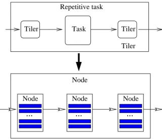
(20) Model Transformations from a Data Parallel Formalism towards Synchronous Languages17. Tiler. 1. Node 2. 2 5 4 4. 5. 6. 7. 8. 9. 6. 7. 8. 9. 6. 7. 8. 9. 6. 7. 8. 9. 3 4 4. 5 5. Figure 9: Transformation of the tiler. GCodeFile2SCodeFile. CodeFile represents the physical file of the related IP. This transformation simply copy fields in a Gaspard CodeFile to fields in a synchronous CodeFile. GASImpl2SImpl. It transforms an Gaspard AbstractSoftwareImplementation to a synchronous Implementation. According to the AbstractSoftwareImplementation, the transformation find the corresponding SoftwareImplementation and then copy its information to the synchronous Implementation. GApplication2SNode. It transforms application components into Nodes. However, all the elements in these Nodes are generated by its three sub-rules, which transform internal structures in the Component into an EquationSystem. This rule contain several sub-rules listed in the following: – GRepetitive2SEquationSystem (see Fig. 10). In this rule, an EquationSystem is first created. And then three types of Equation are created: input tiler Equations, repeated task Equation and output tiler Equations. Tiler connectors are transformed into input/output tiler Equations, which are invocations to Nodes generated by GTiler2SNode, and the internal ComponentInstance is transformed into repeated task Equation. A relevant repeated task Node is then created, in which n equations invoke the task node corresponding to the component that declares the internal component instance.. RR n 6291.
(21) 18. Yu & Gamati´e & Rutten & Dekeyser. Repetitive task Tiler. Task. Tiler Tiler. Node Node. Node. Node. .... .... .... Figure 10: Transformation of the repetitive task Note that hierarchical composition in Gaspard models is preserved in synchronous models by node invocations. – GCompound2SEquationSystem. Each internal ComponentInstance is transformed into an equation. Connectors between these ComponentInstances are transformed into local Signals. – GElementary2SEquationSystem. No Equation is created because its owner Node is implemented externally and Deployment models are used to import its external declarations. However an Interface is created according to the component’s ports. 4.1.2. Illustration of a rule model. These transformation rules are always difficult to describe with natural languages. The complete explanation is very tedious and takes long time for understanding, whereas a curtailed one is always ambiguous for lack of details. It is also impossible to show the implemented code for demonstration. Hence a new language is needed for the efficient description of these transformations. TrML [11] is a TRansformation Modeling Language, which offers a graphical representation of model transformations through: its UML profile, its portable notation which is independent from any existing transformation engines,. INRIA.
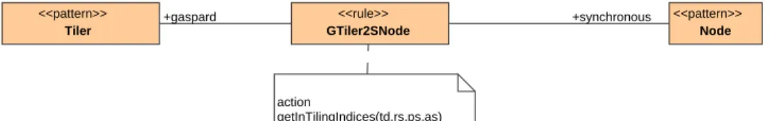
(22) Model Transformations from a Data Parallel Formalism towards Synchronous Languages19. <<pattern>> Tiler. +gaspard. <<rule>> GTiler2SNode. +synchronous. <<pattern>> Node. action getInTilingIndices(td,rs,ps,as). Figure 11: TrML patterns and rule its mechanisms to divide transformation into rules. Furthermore a metamodel is provided for the modeling. Note that model elements are in bold and associations between them are in italics in the following explanation. In a TrML rule (Fig. 11), a transformation is divided into three parts: input pattern (Tiler in Fig. 11), rule (GTiler2SNode), and output pattern (Node). The input pattern indicates the set of model elements to be transformed, which are based on the input model concepts (indicated by gaspard, the association between GTiler2SNode and Tiler). Similarly, the output pattern indicates the set of model elements to be generated, which are based on output model concepts (synchronous). Rule takes the input pattern and transforms it into output pattern. Some external functions used in the transformation are showed in the note (annotation boxes with action). Note that TrML allowes the modeling of bidirectional transformations, but here, only one direction from Gaspard into synchronous is illustrated. A typical transformation is illustrated with the help of TrML. The transformation of a Gaspard Tiler into a Node (Fig. 12), called GTiler2SNode, is detailed in the order of input pattern, rule, and output pattern. The root element of the Input pattern is a Gaspard Tiler. In the transformation, however, more model elements execpt Tiler are needed. These elements can then be found through the associations connected to this Tiler. The TilingDescription stores the tiler’s F, O, P information, which can be found through the tiling. A tiler is connected to, on one hand, a Port through the Source, which indicates the input array of the application component; on the other hand, a PortInstance through the Target, which indicates the input pattern of the repetitions of the internal component. The port is connected to a Shape so as to indicate the array shape. The port instance is connected to ComponentInstance through the componentInstance, from which the shape of its port can be found. The port instance is also connected to Part by the part, from which the shape of repetition space can be found. Finally, from the association of owner of the tiler, the ApplicationPart and then ApplicationModel can be found. Rule is the bridge between input and output patterns. The black box functions used by the transformation are specified in an annotation box that is linked to this rule, for instance, getTilingIndices(td, rs, ps, as) in the annotation box tagged with ”action”. This is a function implemented in Java that calculates the array indices from the tiling information. The arguments of the function come from the input pattern.. RR n 6291.
(23) 20. Yu & Gamati´e & Rutten & Dekeyser. INRIA. Figure 12: TrML representation of a tiler transformation.
(24) Model Transformations from a Data Parallel Formalism towards Synchronous Languages21. The root element of the Output pattern is a Node of the synchronous model. The node is associated with its owner, called Module, by the association owner. The Module can be found through the Gaspard ApplicationModel from the input pattern. All the elements required in the node are then associated to the node. For instance, Interface, EquationSystem and NodeVariables are associated to the node by interface, equations and nodeVariables respectively. Similarly, other elements are associated to Interface, EquationSystem and NodeVariables and so on. Some black box functions can be used during the creations of the model elements and their associations, such as CreatIndexValue(). The transformation illustrated in the Fig. 12 is not a complete transformation because of the lack of expressivity of imperative aspects in TrML, for instance, the iterated creations of Equation, Signal, and IndexValue and the associations of the signals to their index values. Despite of this disadvantage, this graphical transformation language greatly helps to understand syntactic and certain semantic transformations between input/output models. 4.1.3. Implementation of a transformation chain. Gaspard models are specified in the graphical environment MagicDraw, and are exported as Eclipse Modeling Framework (EMF) [9] models. EMF is a modeling framework and code generation facility. In the following transformation phase, these models are transformed into EMF Gaspard models. These two previous transformations will not be detailed here. Then the EMF Gaspard model is transformed into the EMF synchronous equational model, which is finally used to generate synchronous language code (e.g. Lustre code). An automated model transformation chain (Fig. 13) is then defined through the concatenation of these transformations from MagicDraw UML models to data-flow languages.. MagicDraw. Eclipse EMF. UML model. UML model. Model. Gaspard model. Transformation. Synchronous. Synchronous equational model Code generation. Lustre. Code. Figure 13: The detailed transformation chain. These transformations were implemented with the help of specifications, standards and transformation languages. Some of them are briefly presented in this paper. MOF QVT [29] is the OMG standard on model query and transformation, which is respected in transformations presented here. Several other transformation languages and tools, such as ATL [15] and Kermeta [18] already exist. ATL is a model transformation language (a mixed style. RR n 6291.
(25) 22. Yu & Gamati´e & Rutten & Dekeyser. of declarative and imperative constructions) designed w.r.t. QVT. Kermeta is a metaprogramming environment based on an object-oriented Domain Specific Language. But these two languages lack of extension capability specially when some external functions are needed to be integrated into the transformation. EMFT (Eclipse Modeling Framework Technology) project was initiated to develop new technologies that extend or complement EMF. Its query component offers capabilities to specify and execute queries against EMF model elements and their contents. The MoMoTE tool (MOdel to MOdel Transformation Engine), which is based on the EMFT Query and is integrated into Gaspard, is a Java framework that allows to perform model to model transformations. It is composed of an API and an engine. It takes input models that conform to some metamodels and produces output models that conform to other metamodels. A transformation by MoMoTE is composed of rules that may call sub-rules. These rules are integrated into an Eclipse plugin. In general, one plugin corresponds to one transformation. During model transformations, these plugins are automatically invoked one by one.. 4.2. Synchronous code generation from the equational model. The implemented code generation (Fig. 14) from synchronous models is based on EMF JET (Java Emitter Templates) [10]. It is a generic template engine for the purpose of code generation. The JET templates are specified by using a JSP-like (JavaServer Pages) syntax and are used to generate Java implementation classes. Finally, these classes can be invoked to generate source code, such as SQL, XML, Java source code and Lustre (also Signal and Lucid synchrone) in our case. MoCodE (MOdels to CODe Engine) is another Gaspard integrated tool, which works with JET for the code generation. MoCodE offers an API that reads the input models, and also an engine that recursively takes elements from input models and executes a corresponding JET Java implementation class on them. Code generation by MoCodE Lustre code. EMF model. MoCodE engine JET Templates. Java code. Figure 14: Generation of synchronous code from synchronous models.. 4.3. Application examples. Some examples of matrix and image processing have been implemented through the proposed approach and transformation chain exposed in this paper.. INRIA.
(26) Model Transformations from a Data Parallel Formalism towards Synchronous Languages23. 4.3.1. Matrix average. Examples of matrix processing, which averages the patterns from inputs, are intuitive, but they are typical to show the transformation and the application domain. The specification of the chosen example in Gaspard and its explanation can be found in Fig. 2 in section 2. The deployment of the matrix average IP is illustrated in Fig. 15. This deployment indicates where to find the Lustre code that implements the matrix average computing. The physical Lustre code is represented by the CodeFile, and it is associated to the elementary task by the component AbstractSoftwareImplementation, which is composed of at least SoftwareImplementations. This means one elementary task may have several different implementations (in different languages or through different algorithms). The SoftwareImplementation contains the deployment information, for example, the elementary function name, the language of its implementation. Other deployment information, such as ports, etc., can be found in the associations (portImplementedBy, implementedBy) between AbstractSoftwareImplementation and ElementaryTask. <<ElementaryComponent>> <<ApplicationComponent>> TASK i1 : Integer [(2,2)]. o1 : Integer [(1,1)]. <<portImplementedBy>>. <<portImplementedBy>> <<implementedBy>>. <<AbstractSoftwareImplementation>> asiTask <<SoftwareImplementation>> siTask i1. {functionName = "APPLICATION_TASK1" , language = Lustre }. o1. <<manifest>> <<CodeFile>> cfTask1 {filePath = "./eclipse/runtimeConfiguration/demo−simu/exLustre/". }. Figure 15: The deployment of the matrix average IP The example and a video of the transformation chain is located in [16]. The code generated from the transformation is showed in Fig. 16. In this extract of the complete code,. RR n 6291.
(27) 24. Yu & Gamati´e & Rutten & Dekeyser. int^4^4 defines a integer array type with a shape (4,4). In the next, all the generated nodes are explained briefly . APPLICATION_TASK1 is the imported Lustre function, which implements matrix average. TASK_REPETITION is the node in which the repetitions of APPLICATION_TASK1 are built. Each repetition takes a pattern as input and another pattern as output. TILER_INPUT is the input tiler, which takes IA as input array, and produces four patterns: TP0, TP1, TP2, TP3. Note that all the index values are calculated by a black box function in the transformation. TILER_OUTPUT is the output tiler, which takes four patterns: TP0, TP1, TP2, TP3, and build an output array OA. APPLICATION_MATRIX is the main application, which invokes TILER_INPUT_MATRIX, TILER_OUTPUT_MATRIX and TASK_REPETITION. 4.3.2. Image downscaling. Besides the first simple example, which is easy to understand and illustrate, we have other more complicated examples, such as downscaler. In this report, a downscaler from a standard definition TV to a mobile phone screen display will be illustrated (Fig. 17). In this example, a flow of (640∗480)-array will be taken as input (represented by the port with a shape [(640∗480)]), and a flow of (320,240)-array is then produced. In this application, the filter component, which contains horizontal and vertical filter, is repeated 80∗60 times at each instance. And for each repetition of this component, it takes a (8,8)-array as input and produces a (4,4)-array as output. The filter component can be decomposed into two filters, Horizontal filter and Vertical filter. Horizontal filter contains Hfilter, which is repeated 8 times. And each of the repetition takes a (8)-array (resp. (4)-array) as input (resp. output). This is a filter that works only on the first dimension of the array. Vertical filter contains Vfilter, which is repeated 4 times. And each of the repetition takes a (8)array (resp. (4)-array) as input (resp. output). This is a filter that works only on the second dimension of the array. The corresponding generated code can be found in Annex A. But not all code is illustrated because of the big size of the generated code.. INRIA.
(28) Model Transformations from a Data Parallel Formalism towards Synchronous Languages25. node APPLICATION_TASK1 (I1:int^2^2) returns (O1:int^1^1); let O1[0,0] = (I1[0,0]+I1[0,1]+I1[1,0]+I1[1,1])/4; tel node TASK_REPETITION (PI0_0:int^2^2; PI1_0:int^2^2; PI2_0:int^2^2; PI3_0:int^2^2) returns (PO0_1:int^1^1; PO1_1:int^1^1; PO2_1:int^1^1; PO3_1:int^1^1); let PO0_1 = APPLICATION_TASK1(PI0_0); PO1_1 = APPLICATION_TASK1(PI1_0); PO2_1 = APPLICATION_TASK1(PI2_0); PO3_1 = APPLICATION_TASK1(PI3_0); tel node TILER_INPUT (IA:int^4^4) returns (TP0:int^2^2; TP1:int^2^2; TP2:int^2^2; TP3:int^2^2); let (TP0[0,0],TP0[1,0],TP0[0,1],TP0[1,1]) =(IA[0,0],IA[1,0],IA[0,1],IA[1,1]); (TP1[0,0],TP1[1,0],TP1[0,1],TP1[1,1]) =(IA[2,0],IA[3,0],IA[2,1],IA[3,1]); -- (continue in the next column). (TP2[0,0],TP2[1,0],TP2[0,1],TP2[1,1]) =(IA[0,2],IA[1,2],IA[0,3],IA[1,3]); (TP3[0,0],TP3[1,0],TP3[0,1],TP3[1,1]) =(IA[2,2],IA[3,2],IA[2,3],IA[3,3]); tel node TILER_OUTPUT (TP0:int^1^1;TP1:int^1^1; TP2:int^1^1;TP3:int^1^1) returns (OA:int^2^2); let OA[0,0] = TP0[0,0]; OA[1,0] = TP1[0,0]; OA[0,1] = TP2[0,0]; OA[1,1] = TP3[0,0]; tel node APPLICATION_MATRIX (IA0:int^4^4) returns (OA1:int^2^2); var IP0:int^2^2; IP1:int^2^2; IP2:int^2^2; IP3:int^2^2; OP0:int^1^1; OP1:int^1^1; OP2:int^1^1; OP3:int^1^1; let (IP0,IP1,IP2,IP3) = TILER_INPUT(IA0); OA1 = TILER_OUTPUT(OP0,OP1,OP2,OP3); (OP0,OP1,OP2,OP3) = TASK_REPETITION(IP0,IP1,IP2,IP3); tel. Figure 16: Generated Lustre code.. RR n 6291.
(29) 26. Yu & Gamati´e & Rutten & Dekeyser. <<ApplicationComponent>>. Downscaler [(80,60,*)] <<ApplicationComponent>>. Horizontal filter. [(640,480,*)] [(8,8)]. <<ElementaryComponent>> <<ApplicationComponent>> Hfilter [(8)]. <<Tiler>> {paving = "(0,1)" , fitting = "(1,0)" , origin = "(0,0)" }. <<Tiler>>. [(8)]. {paving = " ((8,0,0),(0,8,0),(0,0,1))", fitting = " ((0,1),(1,0),(0,0))", origin = " (0,0,0)"}. <<Tiler>>. [(4,8)]. [(320,240,*)]. {paving = "(0,1)" , fitting = "(1,0)" , origin = "(0,0)" }. [(4)]. <<Tiler>>. <<ApplicationComponent>>. [(4,4)]. Vertical filter. [(8,8)] <<Tiler>> [(4,8)]. {paving = "(1,0)" , fitting = "(0,1)" , origin = "(0,0)" }. <<ElementaryComponent>> <<ApplicationComponent>> Vfilter [(4)] [(8)]. {paving = " ((4,0,0),(0,4,0),(0,0,1))", fitting = " ((1,0),(0,1),(0,0))", origin = " (0,0,0)"}. <<Tiler>> [(4)]. {paving = "(1,0)" , [(4,4)] fitting = "(0,1)" , origin = "(0,0)" }. Figure 17: The downscaler. 5 5.1. Design validation based on synchronous languages General issues. As mentioned before, the intention of the connection between the two previous technologies, namely Gaspard and synchronous languages, is to benefit from the validation tools provided by the synchronous approach for the correct design of data-parallel applications. The verification and analysis offered by synchronous languages can be divided into two sub-domains: functional and non-functional. Functional validation concerns only application (w.r.t. hardware architecture and environment etc.) issues. Safe signal (such as array) assignment and data-dependency analysis are considered as pure functional validation. However, control (such as automata, control clock etc.) verification and simulation have both functional and non-functional aspects. Functional control and simulation are the focus of our work, but the non-functional ones are also worth being studied. Safe array assignment is carried out on Gaspard array values. The core language of Gaspard imposes several constraints on its arrays, such as single assignment. Single assignment indicates that no data element is ever written twice but it can be read several times. This constraint can be easily checked by compilers of Lustre and Signal. Another concern is the partial initialization of Gaspard arrays that may cause problems when the non-initialized array elements are used later. Lustre and. INRIA.
(30) Model Transformations from a Data Parallel Formalism towards Synchronous Languages27. Signal provide different way to address such an issue. Lustre imposes complete initialization that the compiler rejects the programs with partially initialized arrays, whereas Signal fills the non-initialized array elements with default values. Obviously, default values may change the execution results when they are involved in the array computing. Data-dependency analysis includes the causality analysis in synchronous languages. Causality is caused by the self dependence under the instantaneous semantics of synchronous languages. In Gaspard, self dependence may cause deadlock. Two approaches of causality detection are distinguished according to the different mechanisms defined in Lustre and in Signal. In Lustre, specifications are analyzed by the compiler syntactically, and those that have potential causality issues are rejected by the compiler. In Signal, the compiler considers as well a clock analysis to determine the causality, which provides a finer analysis than that of Lustre. This analysis helps to check the existence of deadlocks specified in Gaspard. The deadlocks are not always obvious to be avoided because the specified hierarchy and/or components probably conceal the potential real data dependency. Simulation enables both functional and non-functional verification, performance analysis, etc.. Functional simulation allows the verification of the application correctness through its execution. Both Lustre and Signal provide simulators. Typical examples of the simulation for Gaspard are image processing, such as rotation, filtering, etc.. Together with an image display tool (an ongoing work dedicated to image processing in Gaspard environment), the processing results can be shown directly. Certain non-functional simulation is also studied in Signal language, such as the performance evaluation for temporal validation [19]. Temporal information is associated to the Signal program, from which an approximation of the program execution time can be calculated. Clock analysis is another important validation issue. Although non-functional clock does not represent hardware architecture and the execution environment directly, it is logically related to it. Clock relations specified in the system to some extent reflect the relations that exist between the components in hardware architecture and its environment. These relations can be specified in synchronous languages. Lustre compiler can check the coherence between these clocks. Whereas in Signal, a more complex clock system is built by its compiler on which the verification is carried out. The latter is called Signal clock calculus. With the specified clock relations, some problems, such as clock synchronisability, can be checked. Other non-functional characteristics, such as serialized model (w.r.t. the parallel model), can also be implemented. Details of the clock related analysis can be found in [12]. Control introduced in Gaspard offers the opportunity to enable the flexibility of the application/architecture design. However this flexibility may lead to the undepend-. RR n 6291.
(31) 28. Yu & Gamati´e & Rutten & Dekeyser. ability of the system, such as safety, liveness, schedulability, etc.. Software test may be a solution to verify the system dependability, but they are time-consuming and can not give a complete guarantee. And their test results relies greatly on the chosen scenario/strategy. Model checking is considered as one of key solutions to this issue as the evolution of this technology significantly reduces the difficulty of its usage and the time that it costs. Control can be specified in several forms, such as automata and clock etc., in synchronous languages. In particular, automata based functional control is our first choice because of not only its clear definition of syntax and semantics, but its adoption in synchronous languages. In spite of Statecharts [14], Argos [23] and SyncCharts [2], etc., we are concentrated in Mode-automata, which we can find in Matou [24], Lucid synchrone and Signal etc. Both Lustre and Signal provide model-checking tools, which are called Lesar [32] and Sigali [4] respectively. Another interesting technology is the controller synthesis [25, 26]. It is based on the same principle as model checking, except that it is intended to add control to the system execution to exclude potential bad executions. As mentioned above, the synchronous languages provide the possibilities to verify Gaspard designs without real implementations on SoC. This verification can be classified into two categories: Gaspard related verification and application related verification. Gaspard related verification aims at finding errors in the user’s original design that do not conform to the Gaspard specifications. Hence, the single assignment and the causality analysis belong to this category. However there exist some others designs that comply with Gaspard specifications without providing correct or expected results, i.e., they do not conform to application specifications, such as safety issues and non-functional requirements. Simulation, model checking and clock analysis then belong to this category. In the next, some examples of verification concerning deadlock detection and simulation are presented.. 5.2. Deadlock detection. Currently, the check of absence of dependency cycles in Gaspard specifications, which is still not available in any Gaspard tools, can be carried out with the help of synchronous language compilers. We have experimented causality analysis with different Lustre programs that are generated automatically from Gaspard models in order to verify the absence of dependency cycles which lead to deadlocks in the specifications. A simple analysis. Gaspard imposes deadlock free by construction. A counterexample is then given in Fig. 18. In this example, the Task is a hierarchical component, in which two sub-tasks, t1:Task1 and t2:Task2, execute in parallel. In this hierarchical level, a deadlock, t1.o2 → t2.i2 → t2.o2 → t1.i2 → t1.o2 (→ means ”is needed by”, and t1.o2 signifies port o2 of task t1) can be found easily. Obviously, this application is not allowed in Gaspard because it only adopts deadlock-free specifications.. INRIA.
(32) Model Transformations from a Data Parallel Formalism towards Synchronous Languages29. <<ApplicationComponent>> Task. <<ApplicationComponent>> t1 : Task1 i1 : Integer [(4)]. o1 : Integer [(4)] o1. i1 i2. o2. <<ApplicationComponent>> t2 : Task2 i2. o2 o2 : Integer [(4)]. i2 : Integer [(4)] i1. o1. Figure 18: Causality analysis A finer analysis. The previous case is however too strict for some applications where this type of deadlock is not a real one, i.e., the coarse granularity of analysis hides some real dependencies between components. An example of these applications is illustrated in Fig. 19. Task1 and Task2 in the previous application are illustrated in a finer grain manner. If a new analysis is carried out on this example, then the deadlock previously found is not preserved because the dependencies of t1.i2 → t1.o2 and t2.i2 → t2.o2 do not exit any more. <<ApplicationComponent>> Task1. e1 : ET i1. i1. o1. <<ApplicationComponent>> Task2. e5 : ET. e2 : ET i1. i1. o1. i1. e6 : ET. o1. i1. o1. o1. i1. o1. e7 : ET. e4 : ET. e3 : ET i2. o1. i1. i2. o1. i1. e8 : ET o1. i1. o1. o2. o2. Figure 19: Causality analysis. 5.3. Simulation. In order to verify the functional correctness of applications, the functional simulators are then used. The simulation through the graphical simulator simec [22], which is distributed in the Lustre environment, is illustrated here. The previously mentioned Gaspard application of the matrix average (Fig. 2) illustrates the simulation (see Fig. 20). This figure can be divided into 3 parts: The left one at the top of the figure (box B1) represents the input data of the simulation, which is array of the shape (4,4). So it has 16 elements, whose names start from INPUT ARRAY 0 0 0 to INPUT ARRAY 0 3 3 (their index. RR n 6291.
(33) 30. Yu & Gamati´e & Rutten & Dekeyser. Figure 20: Simulation of the matrix average values are concealed because of the small window size). The right part at the top of the figure (box B2) represents the output array with the shape of (2,2), whose name start from OUTPUT ARRAY 1 0 0 to OUTPUT ARRAY 1 1 1. The button at the bottom of the figure (box B3), called Step, enables the advancement of the simulation step by step.. 6. Related works. There exists another synchronous metamodel, signalmeta [7], which does not have the same idea as the one presented here. It represents a language oriented modeling specifically dedicated to the Signal language. This metamodel completely defines all programming concepts of Signal. It has been specified in the Generic Modeling Environment (GME), developed at Vanderbilt University. Users can visualize the application modeling with the help of this model in GME from which code can be generated. But the model presented in this report act as an intermediate model transformed automatically from the original Gaspard model. Then this model is used to generate synchronous code according to user’s choice. A second difference is that our model does not have the same expressivity as that of signalmeta. signalmeta has the same expressivity as the signal language, but out model has less expressivity that is adequate to data-parallel applications. For instance, the model do not have complex clock mechanism. A model transformation from our model into signalmeta model is possible. Our work aims at the control oriented formal verification at an application level, whereas several other studies on the verification of data parallelism through formal methods [31] have been carried out. These studies focused on some fundamental properties of data parallel paradigm, and they usually adopted some small core languages with the basic primitives of data parallel languages. The first one [21] was based on the functional language, which studies the integration of data parallelism with declarative language. Through the defined functional language, semantics of some parallel data types and the operations on them were studied, and some laws for the transformations of programs and data were proved, etc. The. INRIA.
(34) Model Transformations from a Data Parallel Formalism towards Synchronous Languages31. second study [5] was based on the assertional approach. A new language L, which has the common control structures of some data parallel languages, was defined, and a proof system was built on it. The weakest preconditions calculus was then defined and the associated definability property was discussed. Other works on the projection of Gaspard on formal computation models have been studied, for instance, the simulation of Gaspard specifications in PTOLEMY II [8] and also the projection of Gaspard applications into Kahn process network for the distributed execution [1]. These studies show the practicability of the transformation from Gaspard data-parallelism specifications to other formal models, and also help to some extent to reduce the complexity of the original parallel specifications. But these works did not aim at formal validation issues nor was implemented by using a MDE approach compared to the work presented in this paper.. 7. Conclusions and perspectives. In this paper, we proposed a synchronous metamodel and presented model transformations from data-intensive applications specified in Gaspard into synchronous languages, particularly the Lustre language, through a MDE approach. The implemented code in Java and transformation rules adds up to about five thousands lines of code in Eclipse. Code generators for other languages, such as Signal and Lucid synchrone are still under developing. While the previously presented transformations and validations are directly carried out without any modifications of original Gaspard models, some others can also be envisaged. In general, it requires the introduction of particular concepts in Gaspard, such as clocks, their relations and ”indicators for parallel or sequential mapping”. Synchronizability analysis and serialized models will then be available correspondingly. Hence a special version of Gaspard with these concepts will be studied in order to automatically generate the wellsuited synchronous code. Another future work concerns the integration of control notion inspired by [20] in Gaspard and the transformation of such notions in synchronous languages. This will benefit the flexibility of Gaspard. The model checking on controlled applications will be carried out then for the verification . The controller synthesis is another similar work that enables the correct control of the application. Finally, the way all these analysis results can be exploited by Gaspard users is a challenging perspective from a practical point of view.. References [1] A. Amar, P. Boulet, and P. Dumont. Projection of the array-ol specification language onto the kahn process network computation model. In Proceedings of the International. RR n 6291.
(35) 32. Yu & Gamati´e & Rutten & Dekeyser. Symposium on Parallel Architectures, Algorithms, and Networks, Las Vegas, Nevada, USA, December 2005. [2] Charles Andr´e. Computing SyncCharts Reactions. Electronic Notes in Theoretical Computer Science, 88:3–19, October 2004. http://www.sciencedirect.com; doi:10.1016/j.entcs.2003.05.007. [3] A. Benveniste, P. Caspi, S. Edwards, N. Halbwachs, P. Le Guernic, and R. de Simone. The synchronous languages twelve years later. Proceedings of the IEEE, 91(1):64–83, January 2003. [4] L. Besnard, H. Marchand, and E. Rutten. The Sigali Tool Box Environment. Workshop on Discrete Event Systems, WODES’06, July 2006. [5] Luc Boug´e, David Cachera, Yann Le Guyadec, Gil Utard, and Bernard Virot. Formal validation of data parallel programs: Introducting the assertional approach. In The Data Parallel Programming Model, pages 252–281, 1996. [6] P. Boulet. Array-OL revisited, multidimensional intensive signal processing specification. Research Report RR-6113, INRIA, http://hal.inria.fr/inria-00128840/en/, February 2007. [7] C. Brunette, J.-P. Talpin, L. Besnard, and T. Gautier. Modeling multi-clocked dataflow programs using the Generic Modeling Environment. In Synchronous Languages, Applications, and Programming. Elsevier, March 2006. [8] P. Dumont and P. Boulet. Another multidimensional synchronous dataflow: Simulating Array-Ol in Ptolemy II. Technical Report 5516, INRIA, France, March 2005. available at www.inria.fr/rrrt/rr-5516.html. [9] Eclipse. Eclipse Modeling Framework (EMF). http://www.eclipse.org/emf. [10] Eclipse. EMFT JET. http://www.eclipse.org/emft/projects/jet. [11] A. Etien, C. Dumoulin, , and E. Renaux. Towards a Unified Notation to Represent Model Transformation. Research Report 6187, INRIA, 05 2007. [12] A. Gamati´e, E. Rutten, H. Yu, P. Boulet, and J.-L. Dekeyser. Synchronous Modeling of Data Intensive Applications. Research Report RR-5876, INRIA, http://hal.inria.fr/inria-00001216/en, 2006. [13] N. Halbwachs, P. Caspi, P. Raymond, and D. Pilaud. The synchronous dataflow programming language Lustre. Proceedings of the IEEE, 79(9), September 1991. [14] David Harel. Statecharts: A Visual Formalism for Complex Systems. Science of Computer Programming, 8(3):231–274, June 1987. [15] INRIA Atlas Project. Atl. http://modelware.inria.fr/rubrique12.html.. INRIA.
(36) Model Transformations from a Data Parallel Formalism towards Synchronous Languages33. [16] INRIA DaRT Project. Demos: http://www2.lifl.fr/west/DaRTShortPresentations.. Gaspard2. to. Lustre.. [17] INRIA DaRT Project. Gaspard. http://www.lifl.fr/west/gaspard/. [18] INRIA Triskell Project. Kermeta. http://www.kermeta.org/. [19] A. Kountouris and P. Le Guernic. Profiling of Signal programs and its application in the timing evaluation of design implementations. In Proceedings of the IEE Colloq. on HW-SW Cosynthesis for Reconfigurable Systems, pages 6/1–6/9, Bristol, UK, February 1996. HP Labs. [20] O. Labbani, J.-L. Dekeyser, P. Boulet, and E. Rutten. Advances in Design and Specification Languages for SoCs, Selected contributions from FDL’06, chapter UML2 Profile for Modeling Controlled Data Parallel Applications. Springer, 2007. [21] Bj¨ orn Lisper. Data parallelism and functional programming. In The Data Parallel Programming Model, pages 220–251, 1996. [22] Lustre. [23] F. Maraninchi and Y. R´emond. Argos: an automaton-based synchronous language. Computer Languages, (27):61–92, 2001. [24] F. Maraninchi, Y. R´emond, and Y. Raoul. MATOU: An Implementation of ModeAutomata into DC. In Compiler Construction, Berlin (Germany), March 2000. Springer verlag. [25] H. Marchand, P. Bournai, M. Le Borgne, and P. Le Guernic. Synthesis of DiscreteEvent Controllers based on the Signal Environment. Discrete Event Dynamic System: Theory and Applications, 10(4):325–346, October 2000. [26] H. Marchand, E. Rutten, M. Le Borgne, and M. Samaan. Formal Verification of programs specified with Signal : Application to a Power Transformer Station Controller. Science of Computer Programming, 41(1):85–104, August 2001. [27] Model-Driven Architecture (MDA). http://www.omg.org/mda. [28] Planet MDE. Model driven engineering. http://planetmde.org. [29] Object Management Group. MOF Query / Views http://www.omg.org/cgi-bin/doc?ptc/2005-11-01, Nov. 2005.. /. Transformations.. [30] Object Management Group (OMG). http://www.omg.org. [31] Guy-Ren´e Perrin and Alain Darte, editors. The Data Parallel Programming Model: Foundations, HPF Realization, and Scientific Applications, volume 1132 of Lecture Notes in Computer Science. Springer, 1996.. RR n 6291.
(37) 34. Yu & Gamati´e & Rutten & Dekeyser. [32] Ch. Ratel. D´efinition et r´ealisation d’un outil de v´erification Formelle de Programmes Lustre : Le syst`eme LESAR. PhD thesis, UJF, 1992. [33] L. Rioux, T. Saunier, S. Gerard, A. Radermacher, R. de Simone, T. Gautier, Y. Sorel, J. Forget, J.-L. Dekeyser, A. Cuccuru, C. Dumoulin, , and C. Andre. MARTE: A new profile RFP for the modeling and analysis of real-time embedded systems. In UML-SoC’05, DAC 2005 Workshop UML for SoC Design, Anaheim, CA, June 2005. [34] D.-C. Schmidt. Model-Driven Engineering. IEEE Computer, 39(2), 2006.. INRIA.
(38) Model Transformations from a Data Parallel Formalism towards Synchronous Languages35. A. Generated code for the downscaler. The generated code could be found here. node TILER_INPUT_VERTICALFILTER_1 (Tiler_Input_Array:int^4^8) returns (Tiler_Pattern_0:int^8;Tiler_Pattern_1:int^8; Tiler_Pattern_2:int^8;Tiler_Pattern_3:int^8); let (Tiler_Pattern_0[0],...,Tiler_Pattern_0[7]) = (Tiler_Input_Array[0,0],...,Tiler_Input_Array[0,7]); (Tiler_Pattern_1[0],...,Tiler_Pattern_1[7]) = (Tiler_Input_Array[1,0],...,Tiler_Input_Array[1,7]); ... (Tiler_Pattern_3[0],...,Tiler_Pattern_3[7]) = (Tiler_Input_Array[3,0],...,Tiler_Input_Array[3,7]); tel node TILER_OUTPUT_VERTICALFILTER_2 (Tiler_Pattern_0:int^4; Tiler_Pattern_1:int^4;Tiler_Pattern_2:int^4; Tiler_Pattern_3:int^4;Tiler_Pattern_4:int^4; Tiler_Pattern_5:int^4;Tiler_Pattern_6:int^4; Tiler_Pattern_7:int^4) returns (Output_Array:int^4^4); let (Output_Array[0,0], Output_Array[0,3]) = (Tiler_Pattern_0[0],...,Tiler_Pattern_0[3]); ... (Output_Array[3,0], Output_Array[3,3]) = (Tiler_Pattern_7[0],...,Tiler_Pattern_7[3]); tel node TILER_INPUT_DOWNSCALER_3 (Tiler_Input_Array:int^640^480) returns (Tiler_Pattern_0:int^8^8, ... Tiler_Pattern_479:int^8^8); let (Tiler_Pattern_0[0,0],Tiler_Pattern_0[1,0],. RR n 6291.
(39) 36. Yu & Gamati´e & Rutten & Dekeyser. Tiler_Pattern_0[2,0],Tiler_Pattern_0[3,0], Tiler_Pattern_0[4,0],Tiler_Pattern_0[5,0], Tiler_Pattern_0[6,0],Tiler_Pattern_0[7,0], Tiler_Pattern_0[0,1],Tiler_Pattern_0[1,1], Tiler_Pattern_0[2,1],Tiler_Pattern_0[3,1], Tiler_Pattern_0[4,1],Tiler_Pattern_0[5,1], Tiler_Pattern_0[6,1],Tiler_Pattern_0[7,1], Tiler_Pattern_0[0,2],Tiler_Pattern_0[1,2], Tiler_Pattern_0[2,2],Tiler_Pattern_0[3,2], Tiler_Pattern_0[4,2],Tiler_Pattern_0[5,2], Tiler_Pattern_0[6,2],Tiler_Pattern_0[7,2], Tiler_Pattern_0[0,3],Tiler_Pattern_0[1,3], Tiler_Pattern_0[2,3],Tiler_Pattern_0[3,3], Tiler_Pattern_0[4,3],Tiler_Pattern_0[5,3], Tiler_Pattern_0[6,3],Tiler_Pattern_0[7,3], Tiler_Pattern_0[0,4],Tiler_Pattern_0[1,4], Tiler_Pattern_0[2,4],Tiler_Pattern_0[3,4], Tiler_Pattern_0[4,4],Tiler_Pattern_0[5,4], Tiler_Pattern_0[6,4],Tiler_Pattern_0[7,4], Tiler_Pattern_0[0,5],Tiler_Pattern_0[1,5], Tiler_Pattern_0[2,5],Tiler_Pattern_0[3,5], Tiler_Pattern_0[4,5],Tiler_Pattern_0[5,5], Tiler_Pattern_0[6,5],Tiler_Pattern_0[7,5], Tiler_Pattern_0[0,6],Tiler_Pattern_0[1,6], Tiler_Pattern_0[2,6],Tiler_Pattern_0[3,6], Tiler_Pattern_0[4,6],Tiler_Pattern_0[5,6], Tiler_Pattern_0[6,6],Tiler_Pattern_0[7,6], Tiler_Pattern_0[0,7],Tiler_Pattern_0[1,7], Tiler_Pattern_0[2,7],Tiler_Pattern_0[3,7], Tiler_Pattern_0[4,7],Tiler_Pattern_0[5,7], Tiler_Pattern_0[6,7],Tiler_Pattern_0[7,7]) = (Tiler_Input_Array[0,0],Tiler_Input_Array[0,1], Tiler_Input_Array[0,2],Tiler_Input_Array[0,3], Tiler_Input_Array[0,4],Tiler_Input_Array[0,5], Tiler_Input_Array[0,6],Tiler_Input_Array[0,7], Tiler_Input_Array[1,0],Tiler_Input_Array[1,1], Tiler_Input_Array[1,2],Tiler_Input_Array[1,3], Tiler_Input_Array[1,4],Tiler_Input_Array[1,5], Tiler_Input_Array[1,6],Tiler_Input_Array[1,7], Tiler_Input_Array[2,0],Tiler_Input_Array[2,1], Tiler_Input_Array[2,2],Tiler_Input_Array[2,3], Tiler_Input_Array[2,4],Tiler_Input_Array[2,5],. INRIA.
(40) Model Transformations from a Data Parallel Formalism towards Synchronous Languages37. Tiler_Input_Array[2,6],Tiler_Input_Array[2,7], Tiler_Input_Array[3,0],Tiler_Input_Array[3,1], Tiler_Input_Array[3,2],Tiler_Input_Array[3,3], Tiler_Input_Array[3,4],Tiler_Input_Array[3,5], Tiler_Input_Array[3,6],Tiler_Input_Array[3,7], Tiler_Input_Array[4,0],Tiler_Input_Array[4,1], Tiler_Input_Array[4,2],Tiler_Input_Array[4,3], Tiler_Input_Array[4,4],Tiler_Input_Array[4,5], Tiler_Input_Array[4,6],Tiler_Input_Array[4,7], Tiler_Input_Array[5,0],Tiler_Input_Array[5,1], Tiler_Input_Array[5,2],Tiler_Input_Array[5,3], Tiler_Input_Array[5,4],Tiler_Input_Array[5,5], Tiler_Input_Array[5,6],Tiler_Input_Array[5,7], Tiler_Input_Array[6,0],Tiler_Input_Array[6,1], Tiler_Input_Array[6,2],Tiler_Input_Array[6,3], Tiler_Input_Array[6,4],Tiler_Input_Array[6,5], Tiler_Input_Array[6,6],Tiler_Input_Array[6,7], Tiler_Input_Array[7,0],Tiler_Input_Array[7,1], Tiler_Input_Array[7,2],Tiler_Input_Array[7,3], Tiler_Input_Array[7,4],Tiler_Input_Array[7,5], Tiler_Input_Array[7,6],Tiler_Input_Array[7,7]); ... tel node TILER_OUTPUT_DOWNSCALER_4 (Tiler_Pattern_0:int^4^4, ..., Tiler_Pattern_479:int^4^4, ) returns (Output_Array:int^320^240); let (Output_Array[0,0],Output_Array[1,0], Output_Array[2,0],Output_Array[3,0], Output_Array[0,1],Output_Array[1,1], Output_Array[2,1],Output_Array[3,1], Output_Array[0,2],Output_Array[1,2], Output_Array[2,2],Output_Array[3,2], Output_Array[0,3],Output_Array[1,3], Output_Array[2,3],Output_Array[3,3]) = (Tiler_Pattern_0[0,0],Tiler_Pattern_0[1,0], Tiler_Pattern_0[2,0],Tiler_Pattern_0[3,0], Tiler_Pattern_0[0,1],Tiler_Pattern_0[1,1], Tiler_Pattern_0[2,1],Tiler_Pattern_0[3,1], Tiler_Pattern_0[0,2],Tiler_Pattern_0[1,2],. RR n 6291.
Figure


+7


Documents relatifs
When control reaches a present(S) boolean condition (testing signal presence at the current instant), it may have to postpone execution un- til a consistent definitive value and
L’objectif de cette th`ese est de proposer des approches pour la v´erification formelle de la correc- tion de la mise ` a jour dynamique pour les applications Java Card avec une
The lightweight validating compiler from Lustre to C consists of five main components: A mod- ular compiler from Lustre to C, a test suite generator for Lustre programs, a
One final difficulty of hybrid systems modeling languages is the multiplicity of language constructs. These languages offer the expressiveness, and thus the complexity of a
More- over, the whole calculation of a synchronous program or the generated code is considered as one atomic transition in STS, thus it does not capture the scheduling semantics,
Unit´e de recherche INRIA Rennes, Irisa, Campus universitaire de Beaulieu, 35042 RENNES Cedex Unit´e de recherche INRIA Rhˆone-Alpes, 655, avenue de l’Europe, 38330 MONTBONNOT ST
Unite´ de recherche INRIA Rennes, IRISA, Campus universitaire de Beaulieu, 35042 RENNES Cedex Unite´ de recherche INRIA Rhoˆne-Alpes, 46 avenue Fe´lix Viallet, 38031 GRENOBLE Cedex
L’archive ouverte pluridisciplinaire HAL, est destinée au dépôt et à la diffusion de documents scientifiques de niveau recherche, publiés ou non, émanant des
