DESIGN OF A MARINE GAS TURBINE by
McVey, Hector Lieutenant, Chilean Navy Chilean Naval Academy, 1940
Submitted in Partial Fulfillment of the Requirements for the Degree of
MASTER OF SCIENCE
\~ST. ~
29 ~
Lj~ ;K*~
in
NAVAL CONSTRUCTION AND MARINE ENGINEERING from the
MASSACHUSETTS INSTITUTE OF TECHNOLOGY I r ?946
Signature of Author:
Signature redacted
Department of Naval Architecture and Marine Engineering, 1946 Signature of ProfessorSignature redacted
in charge of Research:Signature of Chairman Department r\
Committee on Graduate Students:
Signature redacted
FRWW-Cambridge, Mass., U. S. A. September, 1946
Professor J. S. Newell Secretary of the Faculty
Massachusetts Institute of Technology Cambridge, Massachusetts, U. S. A. Dear Sir:
In accordance with the requirements for the Degree of Master of Science in Naval Construction and Marine Engineering, I submit herewith a Thesis entitled: Design of a Marine Gas Turbine.
(r'e spectfuk.y,
Signature redacted
Hlector MjveyTABLE OF CONTFNTS
Page
Table of Symbols
1
I.
Summary
5
II.
Introduction
7
III. Procedure
9
IV.
Results
11
V.
Discussion of results
14
VI.
Conclusions and Recomendations
16
VII. Appendix A
17
B
49
C
147
D
217
TABLE OF SYMBOLS A Area in ft. 2; flow area
a Velocity of sound in gas, Ft./sec.,
=
T b Chord of blades in inchesb s Shroud width of blades in inches c Absolute velocity, ft./sec.
C, p Specific heat of air, 0.24 Btu/(lb.)(OF) d Pitch diameter, inches
d Tube diameter, inches D Shell diameter, inches f Friction coefficient
G Mass rate of flow, lbs./sec. Ga Mass rate of flow of air Gf Mass rate of flow of gas
h Isentropic enthalpy drop through turbine, Btu/lb. h Heat transfer coefficient, Btu/(lb.)(OF)(hr) A h Isentropic enthalpy drop through a stage, Btu/lb.
i Enthalpy in Btu/lb.; used to denote a state of the gas.
A1 Small change in enthalpy in Btu/lb. for conditions other than at
constant entropy.
J Mechanical equivalent of heat, 778 ft. x force pounds per Btu. k Ratio of specific heats, Cp/C 1.4 for air.
k Ratio (1-P)/(l P), k. ratio at which stage is symmetrical. k Thermal conductiviey, Btu/(hr)(ft)(deg. F.)
k A Ratio of cross sectional area of gas flow to that of pir flow k u Ratio of film coefficient inside tubes to overall coefficient k - Ratio of flow of gas to flow of air * Ga Gf
G a
1 Blade length, inches L Length of tubes, ft. n Speed in r.p.m. N Number of tubes M Mach number, u/a
M Mass velocity, lbs./sec. x ft.2 o Opening of blades
p Static pressure in psia pr Relative pressure
P Prandtl number,
(Cp')/k
Q Volume rate of flow; ft.3/sec. q Heat input, Btu/lb.
r Overall pressure ratio
r B Combustion chambers pressure ratio ry I Intercooler pressure ratio
Re Reynolds number, (cb)/( trg); DM/p S Number of stages
T Absolute temperature, 0 Fahs. t Thickness of tubes, inches
U Overall transfer coefficient, Btu/(hr)(ft.2)(oF) u Peripheral velocity at pitch diameter, ft./sec. v Specific volume, ft. 3/lb.
w Specific air consumption, lbs/(hr)(H.P.) w Relative velocity, ft./sec.
GREEK LETTERS L,(3 Angles i Density of metal A Small change Clearance, inches Partial derivative Diagram ratio F, Loss coefficient
-'
Efficiencye
Angle of turn of flow through b'ades. Viscosity, lbs.-sec./ft2Velocity ratio
Pi,
3.14159
Blade length-pitch diameter ratio Density of gas or air
Summation
Pitch of blades A function
Angular velocity, rads./sec. SUBSCRIPTS a Stands for air
b Stands for base of blades c Compressor
e Exhaust
f Fuel
i Initial or entering state of gas; internal 1 Leakage
max Maximum
r Relative, relative pressure s Isentropic condition
st Stage
t Turbine; tip of blade th Theoretical
u Component of absolute velocity in the transverse direction w Component of relative velocity in the transverse direction x Component of velocity in thexial direction
W,W.F. Friction and windage o Entering or initial state
1 Entering or initial state; stator 2 Final or leaving state; rotor
I SUMMARY
The object of this Thesis is to investigate the thermodynamic pro-blems involved in the design of a Marine Gas Turbine Plant.
The study will be devoted to the constant-pressure gas turbine cycle. There are many possible arrangements of the elements in the cycle, and the author has selected the arrangement suggested by C. R. Soderberg, which consists of a low pressure compressor coupled to a high pressure turbine; an intercooler, a high pressure compressor coupled to a low pressure tur-bine, a regenerator, and two combustion chambers. The useful power is obtained from the low pressure turbine, while the high pressure turbine constitutes merely a gas generator. The fuel is burned at essentially
con-stant pressure in the combustion chambers.
The author decided to design the plant for a useful power output of 7500 h.p., with a propeller speed of 375 r.p.m. for the power turbine, due to considerations of the size of the reduction gears.
The maximum temperature of the gas at the inlet of the turbines was fixed at 14000 F., which is a little high for the materials now available for turbine construction. It is expected that within a few years this tem-perature will present no problems to the designer, on account of the rapid
developments of the recent years in the field of the metallurgy of steel and its alloys.
The useful power obtained for the plant was 7960 h.p. with an overall efficiency of 37% and an overall pressure ratio of 7. Undoubtedly this is an optomistic result, but considerirg the fact that the author did not take into account parasitic and stray losses, then it is a reasonable result to expect. In any case, it can be said that the gas turbine plant can complete
successfully with the best existing steam power plants, which have an over-all thermal efficiency of about 25%; and it is on an even if not advantageous position with Diesel installations, for which efficiencies of 32 nnd 33% have been attained.
A problem that the gas turbine plant presents in its use as a marine prime mover is the case of reversing, which is a very important fact. No attempt has been made in the present work to present * solution to this pro-blem.
The turbines are of the reaction type, and the compressors of the axial flow type using airfoil type of blades.
II. INTRODUCTION
For a historical background of the development of the gas turbine the author found sufficient information in references (2)*, (4), and (5), and in the interest of brevity it will not be given here.
The information now available for the design proper of a gas turbine is very little; and a great part of the principles, theory, and methods used are based on steam turbine design procedure.
In the arrangement of the elements of the cycle the process is as
follows:
Air at standard atmospheric condtions enters the low pressure compressor where it is compressed to a prescribed pressure, it then goes into the inter-cooler where the temperature of the air is lowered at practically constant pressure, from there it proceeds to the high pressure compressor where it
is again compressed to a higher pressure; after that it enters the regenerator, where it receives heat from the exhaust hot gases; this process is also done at essentially constant pressure; then, the air enters the combustion cham-bers where fuel is injected and burned at constant pressure too. The hot gases then enter the high pressure turbine where they are expanded a pre-scribed amount so that the work delivered by the high pressure turbine is enough to supply the power required by its coupled low pressure compressor and the losses that may occur in this complete branch. From the exhaust of the high pressure turbine the gas enters the second combustion chamber where more fuel is injected and burned at constant pressure until the gas is reheated to the initial turbine inlet temperature. The gases proceed
through the low pressure turbine where they are expanded to atmospheric
* Numbers in brackets designate, from here on, the references in the bibliography at the end of the thesis.
pressure; and finally they enter the regenerator, where they deliver heat to the high pressure air flowing through the tubes; the gases are then exhausted to the stack and to the atmosphere.
III. PROCEDURE
In the development of the design use will be made of the general and derived relations of Thermodynamics and other necessary relations of mech-anics.
The general procedure of the design is as follows:
(a.) Investigation of the cycle, to determine the most efficient over-all pressure ratio and intercooler pressure ratio, that is, the pressure ratio at which the low pressure compressor works. The specific air con-sumption will also be determined.
In connection with the study and calculations of the cycle, the follow-ing assumptions and considerations will be made, and are listed here only, to be explained later when their use comes up:
(1) Standard atmospheric conditions at inlet of low pressure com-pressor.
(2) Compressors and turbines internal efficiency of 0.85. (3) Intercooling to a temperature of 900 F.
(4) Maximum inlet temperature to turbines, 14000 F.
(5) High pressure turbine supplies power only to the low pressure compressor.
(6).Exhaust pressure of low pressure turbine equal to 14.7 psia. (7) Regenerator efficiency of 0.65.
(8) Intercooling, regeneration, and combustion at constant pressure. (9) Neglect parasitic losses.
(b.) Once the overall pressure ratio has been selected the mass rate of
flow is determined based on a required power output of 7500 h.p.
(c.) The next step is to make a preliminr;ry decision on the turbines diameter, number of stages, and speed of rotation.
(d.) Investigation of the characteristics of blades at different angles to the flow and at various degrees of reaction, and based on dimensionless coefficients.
(e.) Preliminary design of the low and high pressure compressors. Determination of the characteristics of the first stage.
(f.)Determination of the characteristics of the blades to use in the design of the compressors. The airfoil N.A.C.A. No. 4409 is to be used. Influence of the Mach number.
(g.) Preliminary decision on compressor and turbine design.
(h.) Detail design of low pressure turbine. Distribution of the work through the stages. Dimensions of the blades in each stage. Performance of the turbine at full power.
(i.) Same as (i) for the high pressure turbine.
(j.) Detail design of the compressors, number of stages, dimensions,
and performance.
(k.) Design of the regenerator.
(1.) Development of the turbine characteristics, in order to predict the partial load characteristic.
(m.) Development of the characteristics of the compressors. (a.) Full load performance and partial load characteristic.
IV. RESULTS Overall pressure ratio, full power
Intercooler pressure ratio Intercooler effectiveness
Turbines:
Pitch diameter, constant Number of stages
Speed of rotation, r.p.m. Gauging
Best inlet angle
Preipheral speed, ft./sec. Flow area at inlet, ft.2 Flow area at exhaust, ft.2 Blade length, first stage Blade length, last stage
Axial width of blades, first stage Clearance, first stage
Clearance, last stage Average Reynolds number Stage efficiency
Reheat factor
Internal efficiency Compressors:
Pitch diameter, constant Airfoil N.A.C.A. No.
Number of stages Speed of rotation, r.p.m. H.P. 26"
7
3525
0.55
800 400 2.743.73
4.79"6.5"
1.66"0.05"
0.06" 180,000 0.891 1.006 0.89617.55"
4409 293525
7
2.65
0.848
L. P.38.5"
14
27000.55
800
455
3.40
9.15
4.04"
10.74"1.35"
0.04"
0.11" 290,0000.891
1.021 0.9128.13"
4409
29
5830
Stagger angle Mach number
Opening pitch ratio of blades Peripheral speed, ft./sec. Flow area at inlet, ft.2 Flow area at exhaust, ft.2 Blade length, first stage Blade length, last stage Blades chord, first stage Blades chord, last stage Clearance, first stage Clearance, last stage Average Reynolds number Stage efficiency Reheat factor Internal efficiency Regenerator: Weight Number of tubes Tube diameter
Wall thickness of tubes Length of tubes
Heat transfer surface Shell diameter Shell thickness
45 0
0.4
0.6
536
1.34
0.69
3.51"
1.8"
1.17"0.6"
0.035"
0.018" 250,0000.868
1.0230.85
450
0.4
0.6
519
3.45
1.775.09"
2.88" 1.8700.96"
0.056"
0.029" 170,0000.868
1.0230.85
20,000 lbs.5760
3/8"
0.02" 15.0 ft. 7500 ft.24.81 ft.
9/32"
19,250 Reynolds number
Turbulent flow
Power output, full load Mass air rate
Overall thermal efficiency
7960 h.p.
64.7 lbs./sec. 37%
V. DISCUSSION OF RESULTS
The overall pressure ratio of 7 was selected in spite of the fact that a better efficiency is obtained with an overall pressure ratio of 19, because it gives less chances of compressor difficulties in their performance. With a high compression ratio leakage problems arise, and consequently good ad-justment of the clearances is necessary, which is not a favorable perspective.
The design of the turbines is perhaps the easiest problem to solve, and the author is quite satisfied with the characteristips obtained. The results are in a fairly good agreement with the few existing gas turbines, and are consistent throughout.
If we compare the gas turbines to steam turbines on the basis of number of stages for the same power output, we see that this design has about the same number of stages to a comparable steam turbine.
In the design of the compressors, many difficulties were encountered. The author estimates that the number of stages is too large for the work the compressors have to perform.
The author was not able to match the speed of the high pressure com-pressor with the speed of the low pressure turbine to which it is coupled; but it was possible to do so in the case of the low pressure compressor and the hivh pressure turbine.
The Reynolds number originally assumed for the investigation of the air-foil characteristics did not agree with the Reynolds number obtained for the low pressure compressor, but it was close enough in the case of the high pressure compressor. In any case, the effect of such discrepancy is of little
neighborhood of the value assumed originally.
The results obtained for the regenerator are fairly good, since it was obtained a value of approximately one square foot of heat transfer surface per horse power output. It can be possible to go to a higher effectiveness for the regenerator, with a consequent gain in efficiency, and only a small increase in weight and volume of the regenerator.
The turbine characteristics were developed for both turbines, and the procedure is indicated in the corresponding part in the Appendix. In regards to the compressors, the author only attempted an approximation to their char-acteristics, since an exact evaluation of the variables involved would require more time than what was available.
The fuel load performance was obtained by placing together the entire design; and the partial load characteristic was not derived but the method to obtain it was given in Appendix D, Section D-3, Part II.
-"~ -~ I
VI. CONCLUSIONS AND RECOMM1ENDATIONS
The author considers that he did not have the time to do a more thorough investigation of all the problems involved in the design.
What requires especial attention is the theory and design procedure of the compressors.
The airfoil N.A.C.A. No. 2409 promised good characteristics too, but the author did not have the chance to study them, and decided to take the airfoil N.A.C.A. No. 4409 for which more complete data was available.
The future of the gas turbine as a marine power plant is indeed brill-iant, even though it has somewhat bulky accessories such as the compressors and the regenerator in particular.
-~ I
SECTION A-1
Part I
Selection of Cycle
The selection of the cycle under which the gas turbine plant is to operate is of the utmost importance. It is obvious that unless the gas turbine plant can compete in efficiency with other types of power plants, its field of application will be restricted.
The combination of compressors, turbines, intercoolers, regenerators, and other parts in a gas turbine plant permits a variety of arrangements.
The author has selected the cycle suggested by C. R. Soderberg in reference (2), because, as he states, that cycle lends itself well for part-load performance. This fact is a very important one in connection with naval ships, since in their lifetime the requirements for develop-ment of full power are small, and most of the time the speed developed is about one-third of the maximum speed, requiring approximately about one-quarter of the full power.
The cycle consists of: two compressors, two turbines, an inter-cooler, a regenerator, and two combustion chambers.
The air enters the Low Pressure Compressor and after being compressed is passed through an intercooler which reduces the temperature, to follow to the High Pressure compressor, from which the compressed air passes through a regenerator to receive some heat of the exhaust gases. Next it enters the first combustion chamber where the temperature is raised by burning fuel at constant pressure, to enter then the High Pressure turbine and deliver part of the work, after which it enters the second
1w
where it delivers heat to the high pressure air, and finally goes to the exhaust.
For a clear understanding refer to Figs. I and II.
The low pressure compressor is connected directly to the H. P. tur-bine, and this turbine delivers power only to move the L. P. compressor. The H. P. compressor is connected to the L. P. turbine which besides delivering power to that compressor it also delivers the useful power to the propeller shaft.
In this arrangement the H. P. turbine is really a gas generator only since it does not deliver useful power to the propeller shaft.
AIM INTAKE T C, - - r - -- -~n [--LA2'vvv2 C - LIP Co.wREwssoiR I. -- IrReCOLER C -- w.~.CoMvEnssow I- SME-RATOR
-YiRST COMB. CHAM3E~IR
T_. H.P. TRb INQ
~-- SECON.D. COMM. CHAOIABER T2- -. TulkiBNE
Wtet
Fie I.
D/AC,RAMATIC AKRANG1WcMENT OF ELEMENT., OF
CYC(e-IMX e 1860 f4L. 6as 8s to Zss 48
)-Part II
Cycle Conditions and-Specifications
The power delivered to the propeller shaft will be fixed at 7500 H. P. It is yet necessary to know better all the requirements of the design of a gas turbine plant, to go to higher powers.
The maximum temperature, at inlet of turbines will be 14000 F., which is a little high considering the present available materials that can withstand the stresses at such a temperature. Nevertheless the author has in mind possible development of special alloys which promise good heat and corrosion-resisting materials.
The internal efficiency of the compressors and turbines will be assumed to be
=
0.85 for the preliminary study of the cycle and thepreliminary design of turbine and compressors. The turbine efficiency is here taken at a rather low value, since there have been cases of an internal efficiency of 0.92. Nevertheless, our assumption is on the
con-servative side anyway.
The regenerator effectiveness will be assumed to be: I
=
0.65. RGreater effectiveness can be obtained, but results in a very big re-generator, which is not desirable in naval practice. This effectiveness will be defined later.
The intercooler discharge temperature will be considered constant and at 900 F. This is a conservative assumption, since all types of
ships have the ocean temperature available, which can safely be considered to have an average temperature of the order of 700 F.
The reheat will be done to the initial tur'ine inlet temperature, that is, 14000 F. (18600 Fa.)
F
In connection with the fact that the compressors are coupled
directly to the turbines, it will be assumed that the mechanical effec-iencies of the turbine and compressor parts of the coupling is * 0.98.
M
In the preliminary computations of the cycle parasitic losses will be neglected.
The initial state of the air entering the low pressure compressor will be assumed to be standard atmospheric conditions that is:
p . 14.7 psia
t
=
700 F. or T = 5200 Fa.With these basic assumptions and specifications, we can proceed to the calculations of the cycle for different conditions.
SECTION A-2
Part I
Cycle Calculations
As stated in Section A-1, the state of the air entering the L. P.
com-pressor is:
Ti
a 5200 Fa.
p
1a 14.7 psia
=l
z.28.77 Btu/lb.
pri = 2.504All calculations will be done using the Air Tables, Reference (10).
For the notation refer to Figs. I and II.
The variables in the cycle are:
over-all pressure ratio
r
/
p/p1
a
P5/P8
intercooler pressure ratio r, p2/pl
The pressure ratios of the turbines, rB, as will be shown later is
tied to the intercooler pressure ratio, once the latter has been fixed the
former becomes also fixed, since the H. P. turbine supplies all its power
to the L. P. compressor, thus being related by the enthalpy drop in the L.P.
compressor and the H. P. turbine.
The values that shall be used for the overall pressure ratio will be:
r
- 4,5,6,7,8,10, and 15.
The values of the intercooler pressure ratio will be varied from
1
to
the value of the overall pressure ratio for the particular case in
condai-deration.
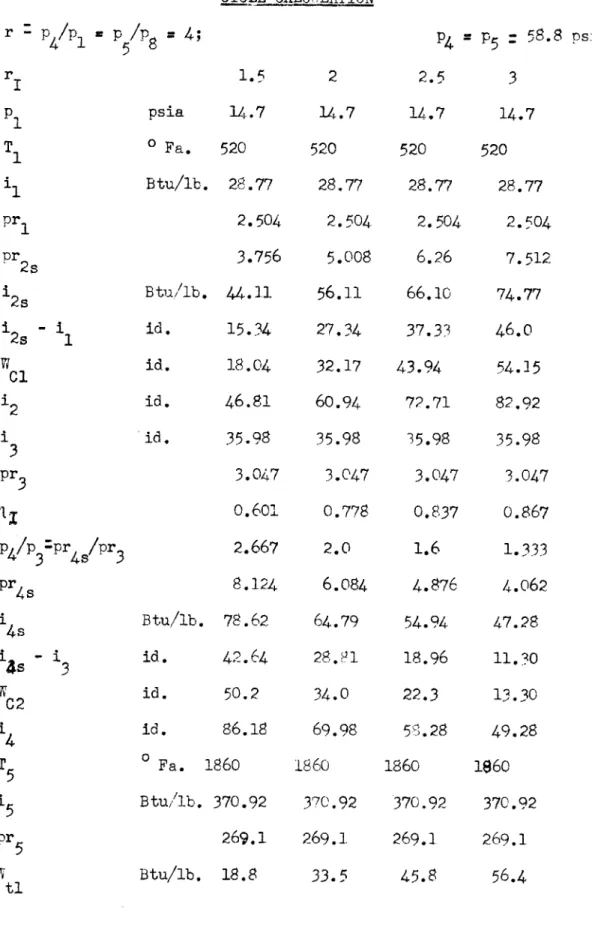
Sample computation for:
r
.4
rT z 1.5Intercooler pressure ratio: r, : p2/p1 = p2/ 1 : pr2 s/pr (1)
1.5
=
p
26/14.7 a pr
2s/2.504
Therefore:
P2
=
P2s : 22.05 psia
and:
pr
2s :
3.756
from the air tables:
1
2s
44.11 Btu/lb.
consequently on fig. II, the isentropic enthalpy raise on the L. P.
com-pressor is:
i
2s
144.11 - 28.77
(2)
15.34 Btu/lb.
and the state of the air at the exhaust of the L. P. compressor is then
given by:
i
2 * 1 + (12s 'i
1)1/-L
(3)
L.
P.
compressor's work:
WC 1= 2- 'il)l/ Ic15.34 x 1/0.85
: 18.04 Btu/lb.
where:
c = compressorts internal efficiency
therefore:
12
: 28.77
+
15.34/0.85
= 46.81 Btu/lb.
S5500 Fa. then:
13
-pr
3=
3.047
The intercooler efficiency can be defined as: i i
I
i
- i 2 1 -46.81
-
35.98
46.81 - 28.77 -0.601
Now: Spr4pr
3p
4/p
3 therefore:pr
.4s
4
L__
x 3.047
1.5
- 8.124P
1_4_ Y P3 15 - x P2p
4=
p
5_4_
x22.05 p -p
5 = 58.8 psia.from air tables:
i
4s
Work done on the compressor:"C2 Consequently:
i
4
= 78.62 Btu/lb.'
4s
-i
c
= 78.62
-
35.98
0.85
= 50.2 Bt/lb.S3
+
C2
86.18 Btu/lb.
The maximum temperature of the air at inlet to turbines has been
(4)
(5)
14_
1.5
and:(6)
35.98 B,9tu,/lb.
: 4 1 p3/pg
fixed at 14000 F.
Therefore:
T
5z 1400
460
a 18600 Fa.
then: 15 . 370.92 Btu/lb.
pr
5: 269.1
Since the H. P. turbine is attached to the L. P. compressor, the
work done by the former must match the work required by the latter, and
as
stated on Section A-1, with our regard to mechanical efficiencies of
the connection.
If it is assumed that the mechanical efficiency of both the L. P.
Com-pressor and H. P. turbine is:
T
:0.98
m
then the mechanical efficiency of the connection is:
=
0.98 x 0.98
M-c
= 0.96
The work required by the L. P. compressor is:
WCi a 18.04 Btu/lb.
then:
W
i
:
18.0 18.8 Btu/lb.
0.96
but:
W
=
5
-
6 therefore:i
6 v 370.92 - 18.8 u 352.12 Btu/lb.The isentropic enthalpy drop across the H. P. turbine is then:
i
5-i
6
(8)
therefore:
i6s x - 22.11
:
370.92 - 22.11=
348.81 Btu/lb.
from the air tables:pr6s
p
6 so that:The reheat is done to
:
225.41
= p6s =
P
5 x pr6 /pr5= 58.8 x 225.41/269.1
=
49.3 psia
a temperature of 14000 F. again, as said in
Section A-1.
T
7:1400
460
-
1860
0 Fa.for which:
1
7u 370.92 Btu/lb.
but, as the reheat us done at constant pressure:
P7
P6 a 49.3 psia
pr
7269.1
The combustion chambers pressure ratio, that is the pressure ratio of
the H. P. turbine is:
r
3: pr
7/pr
8s a p
7/p
8x
P5a 8
p5/p
7a 4/58.8/49.3
=3.35
hence:
pr
8, v 269.1/3.35
a
80.4
for which:
ig8
:
238.29 Btu/lb.
The isentropic enthalpy drop in the L. P. turbine is then:
17
-is
=
370.92
-
238.29
(9)
- 132.63 Btu/lb. and the turbine work is:
for which:
It is desired to have
which can be defined,
(11) Wt2 ( 7 8s) -
132.63 x 0.85
: 112.75 Btu/lb.i8
17 -Wt 2 - 370.92 - 112.75 : 258.17 Btu/lb.T
81440.40
Fa.
t8- 980.40 F.
a regenerator with an effectiveness of: 'R 0.65
according to fig. II as: R =i8 i1 0
i8
-i4and can also be in the form:
R x i
i
84
using form (1la): ig-86.18 z0.65(258.17 - 86.18) 19
=
197.98 Btu/lb.and therefore: T9 - 12080 Fa. From figs. I and II, the heat input will be:
qi :
5
- '9) +*
(7
- '6)
= 370.92
-
197.98
+370.92-
352.12
- 191.74 Btu/lb.
The net work output of the cycle is:
(11)
(1la)
Wnet
:
(18.8+112.75)
-(18.04+50.2)
= 63.31 Btu/lb.and is the useful work to produce the required power. The over-all efficiency of the cycle is then:
Wnet1 (14)
191.74
30.33
The specific air consumption for the cycle and pressure ratios indi-cated is, in pounds of air per horse-power hours:
= 2545
et
(14a)
a 2545
63.31
v = 40.2 lbs./h.p.-hr.
Making the computations as in the foregoing, for various over-all and intercooler pressure ratios, a thorough investigation of the cycle can be done in order to obtain the conditions under which the cycle is most ef-ficient, and this what now follows in tabular form.
TABLE I ClLCLE CALCULATION r -p4/pl - p/8 = 4; r p T ' 1 pr1 pr2s 12s 2s Cl 12
3
pr 3 11 p4/p pr4/pr
3 pr 4 i 4i
-s
i
I
W WC2 45 T 5 i5w
1.5
psia 14.70
Fa. 520 Btu/lb. 28.77 2.5043.756
Btu/lb. 44.11 id. 15.34 id. 18.04 id. 46.81 id. 35.98 3.0470.601
2.667 8.124 Btu/lb. 78.62 id. 42.64 id. 50.2 id. 86.18 0 Fa. 1860 Btu/,lb. 370.92 269.1 2 14.7 520 28.77 2.504 5.008 56. n 27.34 32.17 60.9435.98
3.047 0.778 2.0 6.084 64.79 28.81 34.0 69.98 1860 370.92 269.1 P4 = P5 : 58.8 psia. 2.5 3 14.7 14.7520
520
28.77 28.77 2.504 2.504 6.26 7.512 66.10 74.7737.33
46.0
43.94
54.15
72.71 82.9235.98
35.98
3.047
3.047
0.837
0.867
1.6
1.333
4.876
4.062
54.94
47.28
18.96 11.30 22.3 13.30 5''.28 49.28 1860 1860 370.92 370.92269.1
269.1
-I -~ ________ TABLE I CONTID
6
5
6s
16
pr 6s P6 - F7 I7
,or r7 7 r B pr8s8s
I - i 7 8swt
28
18 - i4I -I
9
4
9
I - I5
9
17 -'6
q1
2 i
C net TV~ w' id. 352.12 id. 22.11 id. 348.81 225.41 psia 49.3 Btu/lb. 370.92 269.1 3.35 80.4 Btu/lb. 238.29 id. 132.63 id. 112.75 id. 258.17 0.65 Btu/lb. 171.99 id. 111.8 id. 197.98 id. 172.94 id. 18.8 0 id. 191.74 id. 131.55 id. 68.24 id., 63.31 0.33 lb/IP-hr 40.2337.42
39.4
331.52
195.1142.6
370.92269.1
2.992.8
251.87 119.05 101.2 269.720.65
199.74
129.8
199.78 171.14 33.50204.64
134.70 66.1768.53
0.335
37.16 325.1253.9
317.02 172.1437.6
370.92
269.1
2. r6 105.0264.15
106.7790.8
280.120.65
221. 84 144.0 202.28168.64
45.80
214.44136.60
66.24
70.36
0.32836.2
314.5266.4
304.52153.99
33.65
37(.92
269.1 2.280 117.6 275.6895.24
81.0 289.920.65
240.64
156.4
205.68
165.24
r-6.40
221.64 137.4067.45
69.95
0. 3154
36.4
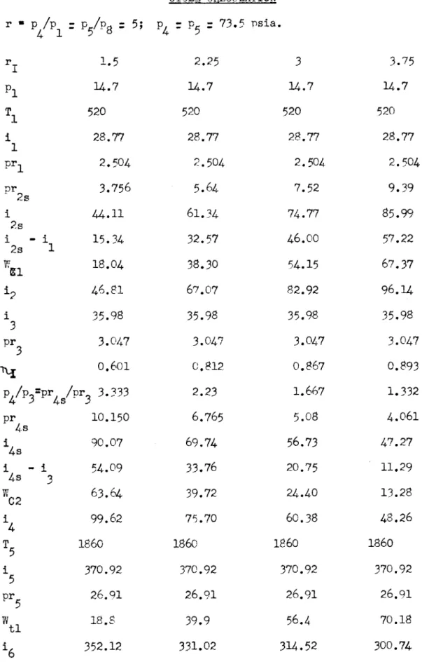
TABLE II CYCLE CALCULATION r
p
4/p
1p
5/P
8=
5; p:p5
:
73.15psia.
r I.5 2.25 3 3.75 p1 14.7 14.7 14.7 14.7 T 520 520 520 520 1 28.77 28.77 28.77 28.77 1 pr 2.504 2.504 2.504 2.504pr2s
3.756
5.64
7.52
9.39
i
44.11
61.34
74.77
85.99
2s i - i1 15.34 32.57 46.00 57.22 2s 1ial18.04
38.30
54.15
67.37
12 46.81 67.07 82.92 96.14i
35.98
35.98
35.98
35.98
3
pr
3.047
3.047
3.047
3.047
0.601 0.812 0.867 0.893p
4/p
3=pr
4/pr
33.333
2.23
1.667
1.332
pr4s
10.150
6.765
5.08
4.061
14
90.07
69.74
56.73
47.27
i - 1. 54.09 33.76 20.75 11.294s
3
C2
63.64
39.72
24.40
13.28
4
99.62
75.70
60.38
48.26
T5 1860 1860 1860 1860 1 370.92 370.92 370.92 370.925
pr5 26.91 26.91 26.91 26.91 I'm -=44i I
-5
16s
pr6s p 617
pr7
rB pr 8s8s
7
wt2~8
LRS-9
9
S-5
7q 1
E w t C Wt I i i i 22.116s
348.81
225.417
61.55
370.92 269.1 4.19 64.2 217.67153.25
8s
130.3
240.620.65
141.0 91.7 191.32 179.6 6 18.8198.4
149.181.68
67.420.34
37.74 TABLE II CONT'D47.0
66.4
323.92
304.52
182.79 153.9949.9
42.0
370.92 370.92 269.1 269.13.4
2.86
79.25
94.1
23.94
253.31
133.98
117.61
113.9 100.0 257.02 270.920.65
0.65
181.32 210.54 117.8 136.8 193.5 197.18 177.42 173.7439.9
56.4
217.32 230.14153.8
156.4
78,02 78.55 75.78 77.850.3485
0.338
33.6
32.7
i 82.5 288.42 132.7936.23
370.92269.1
2.47 109.0 267.92 103.0 87.57283.35
o.65
235.09
152.9 201.16169.76
70.18239.94
157.7580.65
77.1 0.32133.0
r -
p
4/p
1p
5/p8 = 6; ry 1.5 p1 14.7T
520
i 28.77 pr 2.504 pr2s 3.756 i2s 44.11S2s
i
1
15.34
"Cl 18.04 12 46.811
35.98
3
pr3 3.047 0.601 p4/p3=pr /pr 4.0 pr 12.1884s
1 100.034s
14s -i
64.05
%C2
75.35
i x 111.33 T 18605
1 5
370.92
pr5 269.1 vi t18.8 TABLE III CYCLE CALCULATION p4=
p 88.2 psia2.45
3.5
14.7 14.7 520 520 28.77 28.77 2.504 2.504 6.14 8.76465.20
82.45
36.43
53.68
42.90 63.18 71.67 91.9535.98
35.98
3.047
3.047
0.832
0.886
2.45 1.713 7.46 5.22 74.49 57.91 38.51 21.93 45.31 25.80 81.29 61.78 1860 1860 370.92 370.92 269.1 269.1 44.7 65.84.5
14.7520
28.77
2.504
11.2695.65
66.88
78.70 107.4735.98
3.047
0.909
1.333
4.06
47.25
11.27 13.2549.23
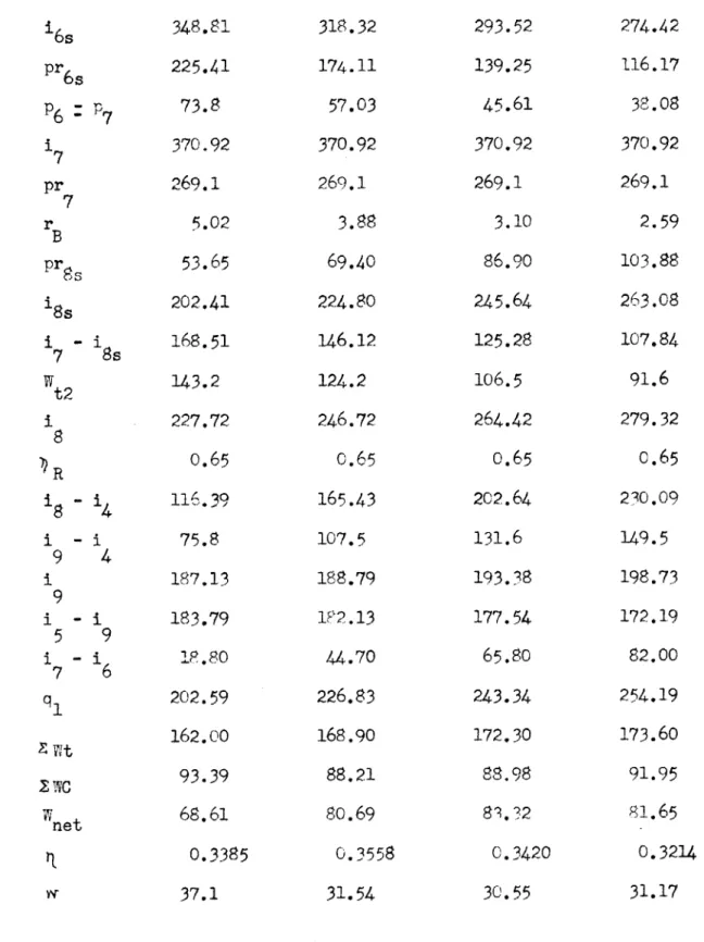
1860 370.92 269.1 82.00TABLE III CONTtD S6s 348.81 318.32 293.52 274.42 pr6s 225.41 174.11 139.25 116.17
P
6p
773.8
57.03
45.61
38.08
7
370.92 370.92 370.92 370.92 pr 269.1 269.1 269.1 269.1 7 r B5.02 3.88 3.10 2.59 B pr 53.65 69.40 86.90 103.88 S8s 202.41 224.80 245.64 263.08i
- i 168.51 146.12 125.28 107.847
Ss
't2 143.2 124.2 106.5 91.6 1 227.72 246.72 264.42 279.32 8R
.65
0.65
0.65
0.65
I - 116.39 165.43 202.64 230.09 8 4 i - i 75.8 107.5 131.6 149.5 9 4 1 187.13 188.79 193.38 198.73 9 I - 1 183.79 1P2.13 177.54 172.195
9
I - 6 18.80 44.70 65.80 82.007
6
q
1202.59
226.83
243.34
254.19
162.00 168.90 172.30 173.607 WC
93.39
88.21
88.98
91.95
Wt 68.61 80.69 8.?2 81.65 net 0.3385 0.3558 0.3420 0.321437.1
31.54
30.55
31.17
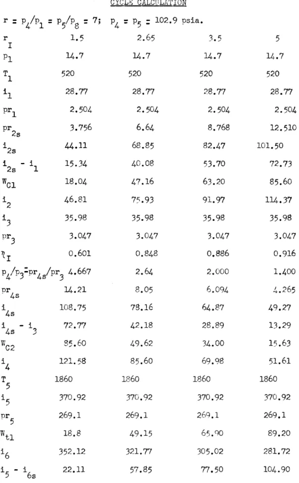
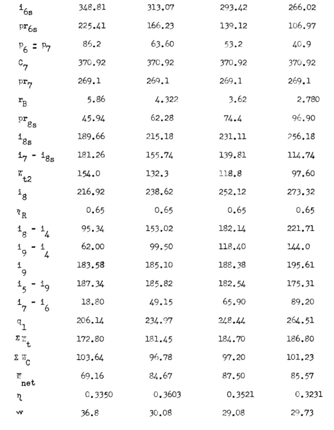
TABLE IV CYCLE CALCULATION r -p
/P
p/ P :7 p: 5 :102.9 psia. 4 1 5 8 4 5 r 1.5 2.65 3.5 p1 14.7 14.7 14.7 T 520 520 520 1 28.77 28.77 28.77 pr1 2.504 2.504 2.504 pr2s 3.756 6.64 8.768 '2s 44.11 68.85 82.4.7 I - i 15.34 40.08 53.70 2s 1 W 1 18.04 47.16 63.20 12 46.81 75.93 91.97 13 35.98 35.98 35.98 pr3 3.047 3.047 3.047 0.601 0.848 0.886 p4,/p3:pr4 /pr3 4.667 2.64 2.000 pr4s 14.21 8.05 6.094 i4s 108.75 78.16 64.87 i - i 72.77 42.18 28.89 4s 3 WC2 85.60 49.62 34.00 i4 121. 58 85.60 69.98 T 1860 1860 1860 5 15 370.92 370.92 370.92 pr 5 269.1 269.1 269.1 49.15 6r,.()5
14.7 520 28.772.504
12.510 101.50 72.7385.60
114.3735.98
3.0470.916
1.400
4.265
49.27 13.2915.63
51.611860
370.92 269.1 89.20TABLE IV CONT'D 16s 348.81 313.07 293.42 266.02 pr6s 225.41 166.23 139.12 106.97
p
6p
786.2
63.60
53.2
40.9
C7 370.92 370.92 370.92 370.92 pr, 269.1 269.1 269.1 269.1 rB 5.86 4.322 3.62 2.780pr
45.94 62.28 74.4 96.90.8s
Ss189.66 215.18 231.11 256.18 17 - is 181.26 155.74 139.81 114.74 t2 154.0 132.3 118.8 97.60 i 216.92 238.62 252.12 273.32 'ZR 0.65 0.65 0.65 0.65 i - i 95.34 153.02 182.14 221.71 i9 - i 62.00 99.50 118.40 144.0 i 183.58 185.10 188.38 195.619
i - 9 187.34 185.82 182.54 175.315
9
5
I -1
18.80 49.15 65.90 89.20 7 6 q 206.14 234.97 248.44 264.51 172.80 181.45 184.70 186.80 z 103.64 96.78 97.20 101.2369.16
84.67
87.50
85.57
net0.3350
0.3603
0.3521
0.3231
36.8 30.08 29.08 29.73r p4/p p5/p8 8; ry 1.5
p
1 14.7 T 1 520 i1 28.77 pr 2.504 1pr
3.756
2s 1 44.11 2s 1 - i 15.34 2s 1 ":' 118.04'2
46.81
S35.98
pr 3.047 0.601p
4/p
3=pr
4s/pr
35.333
pr 16.24 i 116.73 4s 1 - i 80.75 4s3
wC2
95.0014
130.98
T 18605
i
370.92
pr 269.15
T ti18.80 TABLE V CYCLE CALCULATIONp
-p-
117.6 psia. 2.83 4 14.7 14.7 520 520 28.77 28.77 2.504 2.504 7.095 10.016 72.01 89.3743.24
60.60
50.90 71.30 79.67 100.07 35.98 35.98 3.047 3.647 0.858 0.899 2.830 2.00 8.62 6.094 81.60 64.87 45.62 28.89 53.70 34.00 89.68 69.98 1860 1860 370.92 370.92 269.1 269.1 53.00 74.305
14.7 52028.77
2.504 12.520 101.5473.77
86.78 115.5535.98
3.047
0.917 1.6004.875
54.93
18.95
22.3058.28
1860
370.92 269.190.30
i 6
s
pr6s P6 - P76 7 17 pr 7 rB pr 8 18s
7
8s
t2 is -1i84
1
- 49
4
19
i1 -i5
9
7
6
Tinet ti 348.81 225.4198.60
370.92 269.10 6.70 40.18 179.05 191.87163.00
207.920.65
76.94
50.00
180.98189.94
18.80 208.74 181.80113.04
68.76
0. 329237.04
TABLE V CQNT'D308.54
159.64
69.80
370.92 269.14.74
56.78
207.22 163.70 139.20 231.720.65
142.0492.40
182.08 108.3453.00
241.84
192.20 104.60 87.60 0.362429.05
283.50
126.7555.40
370.92 269.1 3.76 71.55 227.56143. 36
121.80 249.120.65
179.14 116.40186.38
184.54
74.30258.84
196.10105.30
90.800.
3503
28.03 264.82 105.71 46.20 370.92 269.1 3.14 85.15 243.70 127.22 108.10 262.820.65
204.54
132.90 191.18 179.7490.30
270.04198.40
10
.08
89.32
0.3300
28.50
TABLE VI CYCLE CALCULATION
r
=
p/p
1p
5/P
8=
10;
p
=
p
5=
147.00 psia.
r
1.5
3.16
5
p1
4.7
14.7
14.7
Ti
520
520
520
11
28.77
28.77
28.77
pr
12.504
2.504
2.504
pr
2,
3.756
7.924
12.520
12s
44.11
77.38
101.54
i
-1
15.34
48.61
72.77
WCl
18.04
57.24
85.58
'2
46.81
85.01
114.35
13
35.98
35.98
35.98
pr
33.047
3.047
3.047
9
0.601
0.857
0.915
p
4/p
3pr
4s/pr
36.667
3.160
2.00
Pr
4 520.32
9.638
6.094
'4s
130.73
87.22
64.87
145
-13
94.75
51.24
28.89
WC2
111.40
60.30
33.97
14
147.38
96.28
69.95
T
1860
1860
1860
5
15
370.92
370.92
370.92
pr
5269.1
269.1
269.1
7
14.7
520
28.77
2.504
17.530
122.15
93.38
109.80
138.57
35.98
3.047
0.935
1.428
4.35
50.16
14.18
16.68
52.66
1860
370.92
269.1
T
15
16s
i 6
pr
6P6
=
P
717
pr
7rB
pr8s
i 8s
17 - i8sWt2
18
nR18
-
14
19
-
14
19
1
5
19
15
9
17
-6q,
z
SC
Tnet
r
22.11
348.81
225.41
123.1
370.92
269.1
8.38
32.12
162.17
208.75
177-40
193.52
0.65
46.14
30.00
177.38
193.54
18.80
212.34
196.20
129.44
66.76
0.3140
38.14
TABLE VI CONT'D 70.20 104.75300.72
266.17
148.79 107.77 81.2 58.9 370.92 370.92269.1
269.1
5.52
4.005
48.74
67.22
194.46
221.93
176.46
148.99
149.95
126.60
220.97
244.32
0.65
0.65
124.69
174.37
81.00
113.30
177.28 183.25193.64
187.67
59.66
89.10
253.30
276.77
209.61 215.70 117.54 119.5592.07
96.15
0.3633
0.3472
27.64 26.47134.40
236.52
78.82
43.05
370.92
269.1
2.93
91.90
251.02
119.90
1C 1. 82
269.10
0.65
216.44
140.60
193.26
177.66
114.30
291.96
216.12
126.48
89.64
0.3068
28.38
-. ___ ____-- -~ TABLE VII CYCLE CALCULATION r
p
4/pP
5/P8
= 15; p4 = P5=
220.5 psia.r
1.5
3.874
5
10
p 14.7 14.7 14.7 14.7 T1 520 520 520 520 1 28.77 28.77 28.77 28.77 pr 2.504 2.504 2.504 2.504 pr2s 3.756 9.700 12.52 25.04 S2s 44.11 87.68 101.54 144.60 2 -1
15.34 58.91 72.77 115.832s
1
WCl 18.04 69.32 85.60 136.20 1 46.81 98.09 114.37 164.97 213
35.98
35.98
35.98
35.98
pr
3.047
3.047
3.047
3.047
0.601 0.896 0.915 0.947 p4/p3 pr4 /pr3lO.00 3.874 3.00 1.500 pr4, 30.47 11.80 9.141 4.570i
158.34
98.25
84.59
52.17
i - 1 122.36 62.27 48.61 16.194s
3
"C2 143.80 73.25 57.21 19.0414
179.78
109.23
93.19
55.02
T5 1860 1860 1860 1860 15 370.92 370.92 370.92 370.92 pr5 269.1 269.1 269.1 269.1 VIt1 18.80 72.21 89.20 141.851-
5
16s
pr
6,
p
617
pr
7rB
pr
8S8s
17
-wt
218
SR19
-19
1-5
1
-7
q
1E
wt
SC
w
net
6s
22.11348.81
225.41P
7184.8
370.92269.1
12.57 21.41134.11
i8s
236.81
201.3
169;62
0.65
14
-10.16
4
to .O 0 0 -H i o 2 m16
18.80
6
209.94
220.10161.84
58.26
0.2775
43.7
TABLE VII CONT'D
85.00
104.95
285.92
265.97
129.69
106.92
106.25
87.60
370.92
370.92
269.1
269.1
7.23
5.96
37.23
45.17
173.19
188.30
197.73
182.62
168.00
155.20
202.92
215.72
0.65
0.65
93.69
122.53
60.88
79.62
170.11
172.81
200.81
198.11
72.21
89.20
273.02
287.31
240.21
244.40
142.57
142.81
97.64
101.59
0.3575
0.3539
26.06
25.03
166.90
204.02
54.69
44.81
370.92
269.1
3.047
88.40
247.26
123.66
105.10
265.82
0.65
210.80
137.00
192.02
178.90
141.85
320.75
246.95
155.24
91.71
0.2693
27.72
0:56 0.15
~
O~fl~i~ /4-7 /t-i4w
Xor7R'Oile~ -PRSSR -RT/ J~rr 0.45Q YC~E -$~~,RCON$~~
OV0R t.L EsVR e 'A rio P~~orr~ Fb~t P~w&#,.? I RC9Q4E1 9 E$R i'iir
1)
1 -to I. It -- tic -, IC 10 N P~.It -,
O-VERis RE~SSURE 7?ATio - V
0.5 0.4 670 U 'Ii 4 U 0.2 0.1 0 0 74 .
$ c
;
oQfpoI 45 40 /AI4~T COA9ZrT'0N P7 , - v07* ir=4 35[
30 26 X 0r to is toSECTION A-3 Part I
Specific Air consumption
From the calculations on Section 2 it can be seen that the best efficiency is obtained with an overall compression ratio p
/p-
10. Nevertheless, this is a rather high value for the compressors to work at, especially axial flow type. Consequently a lower value must be chosen. It can be noticed that for r=
7, the cycle efficiency is only slightly less; therefore this will be the value for which the design will be developed.It can also be seen that the best efficiency in the cycle occurs with an intercooler pressure ratio of r1 :
/~T:
2.65.
The specific air consumption can now be found by:
hp 3600 G(Wnet - Leaving Loss) - PF7. (15)
2545
Where: G specific air consumption in lbs./sec.
power loss, due to friction and windage, which shall be WF
taken as 2% of the net shaft horsepower required. It is to be noted that this consideration will be considered valid only at full power. For partial loads this loss will vary roughly with the square of the r.p.m.
From the computations for the cycle in Section 2: p4/pl - 7 and r = p2/p 1 2.65
w
- 84.67 Btu/lb. net-The leaving loss shall be considered, as a preliminary assumption, as equal to 1.2% of the L. P. turbine enthalpy drop.
Leaving loss hL : 0.012 x 84.67 . 1.02 Btu/lb. From the statement of the problem, the power required is
Therefore: PFW 0.02 x 7500 * 150 h.p. And: 7500 3600 G (84.67 - 1.02) - 150 2545 - G 64.7 lbs. air/sec.
SECTION B-l Preliminary Characteristics of L. P. Turbine
The first step is to determine the preliminary turbine mean diameter at the exhaust.
Some limitations are necessary though; limitations which will be explained as they are given.
(a) Blades tip speed limit of 500 ft./sec. for the hottest stage. Since it is a well known fact that the strength of alloys used in turbine construction decreases rapidly with increase in tem-perature, a limit must be set for the maximum stress that a blade can be subjected to, in order as to assure working of the
turbine without mishaps. This is one of the most important topics in gas turbine design. If alloys can be obtained that show a good strength at high temperatures, the gas turbine can be put in an advantageous position over other kinds of prime
movers.
(b) No appreciable inlet velocity to low pressure compressor.
(c) The ratio of blade length to pitch diameter will be 1/d = 0.28. It can be shown that for a constant circulation stage, to obtain a zero pressure change across the base of the rotor blade, the ratio 1/d should not exceed 0.3; this is absolutely true for isentropic conditions throughout, Pnd for k
=
1.4 (ratio of specific heats).(d) Axial flow at discharge of turbine, to be assumed.
Part I
Pitch Diameter
The pitch diameter can be determined as a function of the leaving area, or exhaust area, and from an estimate of the leaving loss.
The leaving loss can be expressed as: AhL C eGv 2 e) 1-;1
2g A2e 2gJ (16)
Where: C2 axial component of flow at exhaust G
=
specific air consumptionv2e specific volume of gas at the exhaust, which can be determined from the computations of the cycle on sec-tion A-2, Appendix A, for the pressure ratio selected. Consequently: v 2 RT
=
53.35 x 1360.5 2e e P- 14.7 x 144 (17) 3 34.26 ft.3/lb. Therefore: Exhaust area: Ae Gv2e V2gJ hL (16)64.7 x 34.26 (AhL 1.02, see section
V64.4 x 778 x 1.02 A-3 Part I)
* 9.05 ft.2
From fig. VI: A e dl
-i 2(l) -t d d 144 d
=
_14FEx A x (d) w 1 (18)Substituting the corresponding values:
d
=
/'jx
9.05
x(_
.
w 0.28
=
38.5 inchesF ic
-I
-Part II
Stage Characteristics
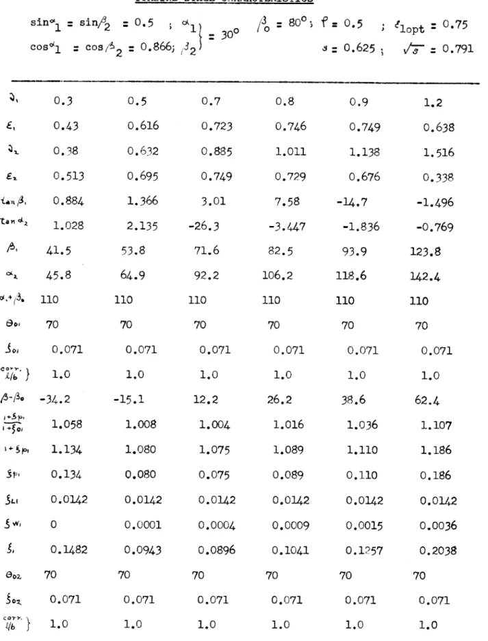
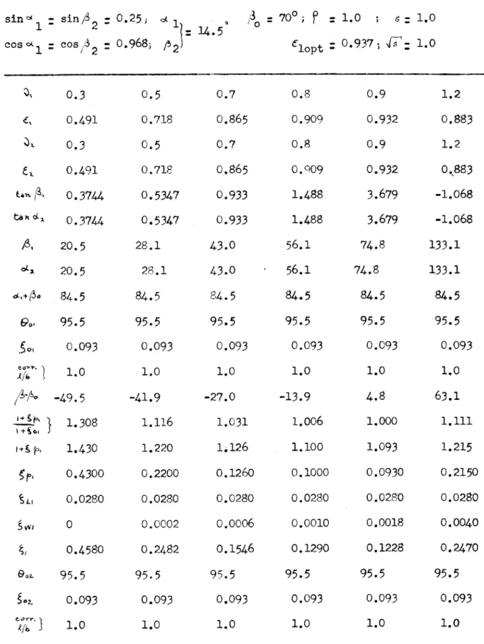
Before going into the determination of the number of stages required, it is necessary to find some characteristics of typical reaction stages, based on dimensionless factors, in order not to commit ourselves to particular dimensions.
A brief exposition of the derivation of the most important formulas to be used in connection with the determination of the stage characteristics follows.
To simplify calculation and derication of the formulas a symmetrical stage will be considered.
By defining stage efficiency as:
= Work output from stage
Work input to stage (19)
and the following concepts, which can be easily understood by observing fig. IX and X:
Stator velocity ratio 1
u u
c 1 1(20) where ul is the peripheral velocity u.
Stator diagram ratio:
e
: 1(2cos 1 (21)Similarly for the rotor:
S- U 2 :u
2 - (22)
v2 '"2
and 2 = 2(2cos 2 2 (23)
It is necessary to define also a factor S, which depends on the degree of reaction
( )
of the blade, and is equal to:s5 - - ( - f ) E 1(24)
The necessity of this factor can be readily seen from fig. VII, where 2: l -(1 - )2
2 2 s.C