Design Methods in the Aerospace Industry: Looking for Evidence of
Set-Based Practices
by
Joshua I. Bernstein
Master of Engineering Aeronautics and Astronautics Massachusetts Institute of Technology, 1997 Bachelor of Science Mechanical Engineering
The Johns Hopkins University, 1996
Submitted to the Technology and Policy Program in partial fulfillment of the requirements for the degree of
MASTER OF SCIENCE at the
MASSACHUSETTS INSTITUTE OF TECHNOLOGY May, 1998
© Massachusetts Institute of Technology, 1998 All Rights Reserved
Author ________________________________________________________________________ Technology and Policy Program May 8, 1998
Certified by ____________________________________________________________________ John Deyst Professor, Departments of Aeronautics and Astronautics
Accepted by ___________________________________________________________________ Richard de Neufville Chairman, Technology and Policy Program
3
Design Methods in the Aerospace Industry: Looking for Evidence of
Set-Based Practices
by
Joshua I. Bernstein
Submitted to the Technology and Policy Program on May 18, 1998 in partial fulfillment of the requirements for the degree of Master of Science in Technology and Policy.
Abstract
A new paradigm in engineering design, known as set-based concurrent engineering (SBCE), has been proposed which seems to offer advantages over more traditional techniques. This research, therefore, had three goals: 1) to develop a clear understanding of the definition of SBCE and to contrast that definition with other theories, 2) to assess the “set-basedness” of the aerospace industry, and 3) based on the assessment, to propose a model for implementing SBCE within an aerospace development project. While set-based concurrent engineering consists of a wide variety of design techniques, the basic notions can be stated in two principles: 1) engineers should consider a large number of design alternatives, i.e., sets of designs, which are gradually narrowed to a final design, and 2) in a multidisciplinary environment, engineering specialists should independently review a design from their own perspectives, generate sets of possible solutions, and then look for regions of overlap between those sets to develop an integrated final solution. This research found that while no company’s design process completely fulfilled both of these criteria, many set-based techniques are used within the aerospace industry. Building on some of the observed industry practices, a design process model is proposed which combines concepts from lean manufacturing, such as “flow” and “pull,” to implement set-based concurrent engineering.
Thesis Supervisor: John Deyst
5
Acknowledgements
Many people have assisted me in the endeavor now represented by this thesis. Without their time, effort, advice, and support I could never have completed this work.
I first owe my gratitude to the Lean Aerospace Initiative, which funded this research. LAI represents a unique opportunity for a graduate student to work directly with members of the aerospace industry, and I consider myself very fortunate to have been able to make a contribution to this effort.
LAI is not simply an abstract organization, however. I owe a great debt to the many people who are LAI. First, I must thank my site visit coordinators and escorts at the companies which I visited. They were willing to take one, two, or even three days off from their busy work schedules to show a wide-eyed graduate student how aerospace systems really are designed and developed. In addition, I thank the many engineers and managers who were willing to spend an hour or two sharing the details of their work. Though these people must remain nameless in this document, I thank them all.
I also must thank my advisors. First, Professor John Deyst. John has advised me now for two years, over the course of two Masters degrees and two theses. I have valued his time and assistance and his genuine concern for my academic experience.
During this work I have also been fortunate to be able to call upon an array of additional advisors. Within LAI, I thank Professor Earll Murman, Professor Stan Weiss, and especially Dr. Joyce Warmkessel and Dr. Eric Rebentisch for their time and advice. I was fortunate enough to meet Dr. Bill Finch, a “kindred spirit” here at MIT in the realm of set-based concurrent engineering. Without his willingness to listen to my ramblings on several late nights, I would not have been able to pull this work together.
I must also thank my “advisors at large,” Professor Al Ward, at the University of Michigan, and Professor Durward Sobek, at the University of Montana. Al and Durward are some
of the original developers of the theory of set-based concurrent engineering, and their advice and input were essential to my work.
Finally, I must thank my family: Mom, Pop, Jesse, and especially my wife, Ritu. Without their support, none of this would have been possible.
7
Table of Contents
A B S T R A C T . . . 3 A C K N O W L E D G E M E N T S . . . 5 TABLE OF CONTENTS . . . 7 L I S T O F F I G U R E S . . . 1 5 LIST OF TABLES . . . 1 9 1 . I N T R O D U C T I O N . . . 2 1 1.1 MOTIVATION AND OBJECTIVES OF THIS RESEARCH...211.2 THESIS OVERVIEW AND OUTLINE...22
2 . P O I N T - B A S E D A P P R O A C H E S A N D C O N C U R R E N T E N G I N E E R I N G . . . 2 3 2.1 CHAPTER INTRODUCTION...23
2.2 POINT-BASED STRATEGIES...23
2.3 POINT-BASED STRATEGIES AND CONCURRENT ENGINEERING...24
2.3.1 Traditional Approaches to Product Development: Over the Wall...24
2.3.2 The Separation and Integration of Knowledge...25
2.3.3 Transitioning to Concurrent Engineering...31
2.3.4 Interteam Communication: An Integration Problem...34
2.3.5 Task Sequencing...35
2.3.6 Establishing Requirements in the Point-Based Approach and Doing It Right the First Time...36
2.5 SUMMARIZING THE CE SOLUTION...39
3 . DEFINING SET-BASED CONCURRENT ENGINEERING . . . 4 1 3.1 CHAPTER INTRODUCTION...41
3.2 THE TRIPLE PROBLEM: FACTORS MOTIVATING THE NEED TO DELAY DECISION-MAKING...41
3.3 THE NEED FOR A PARADIGM SHIFT...47
3.4 SET-BASED CONCURRENT ENGINEERING DEFINED...47
3.4.1 An Introductory Summary...47
3.4.2 Developing Sets of Alternatives...49
3.4.3 Using Sets to Communicate and Guide Development...50
3.4.4 Using Sets to Integrate and Optimize a Design...54
3.4.5 Requirements in the Set-Based Context...55
3.4.6 Managing Set-Based Concurrent Engineering...56
3.5 OTHER METHODS WHICH RECOMMEND CARRYING OPTIONS...57
3.5.1 Two Examples...57
3.5.2 Contrasting These Methods with SBCE: Different but Highly Complimentary...60
3.6 SBCE VERSUS PLATFORM DESIGN...61
3.7 SUMMARIZING SET-BASED CONCURRENT ENGINEERING...62
4 . E X A M P L E O F S B C E F R O M T O Y O T A A N D I T S S U P P L I E R S . . . 6 7 4.1 INTRODUCTION: “THE SECOND TOYOTA PARADOX”...67
4.2 SET-BASED PRACTICES WITHIN TOYOTA...68
4.2.1 Design Organization...68
4.2.2 A Quick Overview of the Process Highlighting the Use of Sets...69
4.2.3 Discussion of the Process: The Relationship between Upstream and Downstream Groups and the Use of Standardized Processes...72
9
5 . ASSESSING THE “SET-BASEDNESS” OF THE AEROSPACE INDUSTRY: SETTING
THE STAGE . . . 7 7
5.1 CHAPTER INTRODUCTION...77
5.2 RESEARCH DESIGN...77
5.3 OVERVIEW OF RESULTS...81
5.4 COMMON THEMES: AN EXAMPLE...82
5.5 DISCUSSION...85
5.5.1 Conceptual Design Processes...85
5.5.2 The Departure of the Conceptual Designers...87
5.5.3 Relationships between Engineers...88
5.5.4 The Impact of the Contracting Environment...89
5.5.5 The Analysis Cycle as a Driver of the Design Process...90
5.5.6 Long Lead Items as Drivers of the Design Process...91
5.6 COMMON THEMES: IN CLOSING…...91
6 . E X A M P L E S O F D E S I G N S T R A T E G I E S . . . 9 3 6.1 CHAPTER INTRODUCTION...93
6.2 EXAMPLE 1: CAPITALIZING ON THE POINT DESIGN...93
6.2.1 Introduction and the Underlying Theme: Speed...93
6.2.2 Approach to Requirements and the Limitation of the Method...94
6.2.3 “Just Do It” Design: The 80/20 Rule, Select an Option Quickly, and Plan for Success...96
6.2.4 Making the Method Work: Robustness, People, and Small Teams...100
6.3 DISCUSSION OF EXAMPLE 1...101
6.4 EXAMPLE 2: DESIGN BY CONSTRAINT...103
6.4.1 Introduction...103
6.4.2 A Multi-Tiered Approach...103
6.4.4 Additional Issues...109
6.5 DISCUSSION OF EXAMPLE 2...111
6.6 EXAMPLE 3: COMBINING PARALLEL CONCEPT DEVELOPMENT WITH CONCEPTUAL ROBUSTNESS...113
6.6.1 Development of Parallel Design Concepts to Explore the Design Space...113
6.6.2 Conceptual Robustness...114
6.7 DISCUSSION OF EXAMPLE 3...115
6.8 EXAMPLE 4: SUBSYSTEM INSTALLATION...116
6.8.1 Overview of the Design Dilemma...116
6.8.2 New Developments...117
6.9 DISCUSSION OF EXAMPLE 4...118
6.10 DESIGN STRATEGIES: POINT-BASED, WITH HINTS OF SETS...119
7 . V I R T U A L P R O D U C T D E V E L O P M E N T T O O L S . . . 1 2 1 7.1 CHAPTER INTRODUCTION...121
7.2 EXAMPLE 5: AN INTEGRATED DESIGN AND ANALYSIS PACKAGE...121
7.3 DISCUSSION OF EXAMPLE 6...124
7.4 EXAMPLE 6: USING COMPUTER TOOLS TO INSTITUTE A PROCESS-BASED DESIGN METHOD...125
7.4.1 Introduction and Overview...125
7.4.2 The Ideal Design Environment...126
7.4.3 Involving Downstream Activities...128
7.4.4 Convergence Range and Decision Gates...128
7.4.5 Database Management...130
7.4.6 Pending Issues...130
7.5 DISCUSSION OF EXAMPLE 6...131
7.6 CONCLUSIONS: THE CHALLENGES IN IMPLEMENTING VIRTUAL PRODUCT DEVELOPMENT TOOLS...132
8 . STANDARD PRODUCTS AND PRACTICES . . . 1 3 5 8.1 C I ...135
11
8.2 EXAMPLE 7: A COMPANY BEGINNING TO IMPLEMENT A PLATFORM STRATEGY...135
8.2.1 Background: Motivation; Basic Advantages and Disadvantages...135
8.2.2 Materials and Processes (M&P): Integrating Standard Materials and Manufacturing Processes into Design 137 8.2.3 Electronics Packaging: Developing Evolving Standards...138
8.2.4 Standard Designs and Decision Making...139
8.2.5 Standardizing the Design Process...143
8.2.6 Standard Designs and Their Effects on Design Organizations...146
8.3 EXAMPLE 8: THE EVOLUTION OF STANDARDIZED PRODUCTS AND PROCESSES...147
8.3.1 The Development of a Gated Process...147
8.3.2 Designing the Design Organization...151
8.3.3 Product Design...151
8.3.4 Taking Advantage of the World Wide Web...153
8.3.5 Influencing Requirements...154
8.4 DISCUSSION OF EXAMPLES 7 AND 8...155
8.5 EXAMPLE 9: DESIGN RE-USE...156
8.6 DISCUSSION OF EXAMPLE 9...158
8.7 SUMMARIZING STANDARDIZED PRODUCTS AND PROCESSES...159
9 . S E T - B A S E D A P P R O A C H E S A N D T H E I N F L U E N C E O F C O S T . . . 1 6 1 9.1 CHAPTER INTRODUCTION...161
9.2 EXAMPLE 10: THE COST OF CONSIDERING ALTERNATIVES...161
9.3 EXAMPLE 11: THE IMPACT OF COST AS AN INDEPENDENT VARIABLE...163
9.3.1 Introduction...163
9.3.2 Implementation...164
1 0 . AN INDUSTRY PERSPECTIVE: CONSTRAINTS, THE ASSESSMENT, AND A SUMMARY . . . 1 7 1
10.1 CHAPTER INTRODUCTION...171
10.2 CONSTRAINTS ON THE DESIGN PROCESS...171
10.2.1 Suppliers...171
10.2.2 The Limits of Parametric Models...173
10.2.3 Communicating with the Customer...174
10.3 HOW SET-BASED IS THE AEROSPACE INDUSTRY?...175
10.3.1 Three Answers...175
10.3.2 Implications of the Answers...176
10.4 LESSONS FROM THE EXAMPLES...177
1 1 . A M O D E L F O R L E A N S E T - B A S E D C O N C U R R E N T E N G I N E E R I N G . . . 1 8 1 11.1 CHAPTER INTRODUCTION...181
11.2 WHEN SHOULD SBCE BE USED?...182
11.3 AN ANALOGY: HOW DESIGN IS LIKE MANUFACTURING...183
11.4 THE MODEL FOR LEAN SET-BASED CONCURRENT ENGINEERING...185
11.4.1 Why is the Concept of Lean Important to SBCE?...186
11.4.2 Definitions: Operations versus Processes...186
11.4.3 Improve Processes, then Operations...187
11.4.4 Start in the Factory...188
11.4.5 Understand Value...189
11.4.6 Eliminate Waste...190
11.4.7 Organize Design Teams to Mirror the Product Architecture...191
11.4.8 Standardize Design Operations...193
11.4.9 “Right-Size” Design Tools...195
13
11.4.11 Educate the Customer...197
11.4.12 The Concept of Flow...197
11.4.13 Controlling Flow with Pull...198
11.4.14 Using Sets to Achieve Flow...199
11.4.15 Using Pull to Control the Flow of Sets...201
11.4.16 Apply the Principles of SBCE to Ensure a Globally Optimal Solution...202
11.4.17 Ensuring that Learning Occurs throughout the Process...203
11.5 SUMMARIZING THE MODEL...204
1 2 . C O N C L U D I N G T H O U G H T S . . . 2 0 5 12.1 POLICY ISSUES AND IMPLICATIONS...205
12.2 FINAL THOUGHTS ON SBCE AND THE AEROSPACE INDUSTRY...207
12.3 RECOMMENDATIONS FOR FURTHER RESEARCH...207
WORKS CITED . . . 2 0 9
15
List of Figures
FIGURE 1: "OVER THE WALL” PRODUCT DEVELOPMENT. TRADITIONAL METHODS OF ENGINEERING DESIGN
EMPLOYED LITTLE COORDINATION BETWEEN UPSTREAM AND DOWNSTREAM TASKS, LEADING TO THE NEED
FOR CONSIDERABLE BACKTRACKING AND REWORK IN THE DEVELOPMENT PROCESS. (ADAPTED FROM WOMACK
AND JONES, P. 107)...25
FIGURE 2: UPSTREAM-BASED DESIGN. DOWNSTREAM DESIGN KNOWLEDGE IS ASSIMILATED BY THE UPSTREAM
DESIGN GROUP, ALLOWING THE UPSTREAM GROUP TO POSSESS ALL OF THE KNOWLEDGE REQUIRED TO SOLVE
THE DESIGN PROBLEM. (ADAPTED FROM VON HIPPEL, 1995)...28
FIGURE 3: DOWNSTREAM-BASED DESIGN. UPSTREAM DESIGN KNOWLEDGE IS ASSIMILATED BY THE DOWNSTREAM
DESIGN GROUP, ALLOWING THE DOWNSTREAM GROUP TO POSSESS ALL OF THE KNOWLEDGE REQUIRED TO
SOLVE THE DESIGN PROBLEM. (ADAPTED FROM VON HIPPEL, 1995)...28
FIGURE 4: ITERATIVE DESIGN. THE UPSTREAM DESIGN GROUP FIRST DEVELOPS A PROTOTYPE WHICH THE
DOWNSTREAM GROUP REVIEWS AND MODIFIES. THE PROCESS CONTINUES UNTIL BOTH GROUPS ARE SATISFIED
WITH THE DESIGN. (ADAPTED FROM VON HIPPEL, 1995)...29
FIGURE 5: SUB-PROBLEM DESIGN. THE DESIGN PROBLEM IS DECOMPOSED INTO SMALLER PROBLEMS WHICH EACH
GROUP CAN SOLVE INDEPENDENTLY. (ADAPTED FROM VON HIPPEL, 1995)...30 FIGURE 6: MODES OF UPSTREAM AND DOWNSTREAM INTERACTION. MODES 1 AND 2 PERMIT LITTLE (IF ANY)
INTERDISCIPLINARY PROBLEM SOLVING BETWEEN UPSTREAM AND DOWNSTREAM GROUPS, WHILE MODES 3
AND 4 ALLOW PROGRESSIVELY GREATER INTERACTION. (ADAPTED FROM WHEELWRIGHT AND CLARK, P.
178)...31
FIGURE 7: DESIGN IN THE CE ENVIRONMENT. IN CONCURRENT ENGINEERING, BOTH UPSTREAM AND
DOWNSTREAM DESIGN GROUPS SIMULTANEOUSLY PARTICIPATE IN THE DEVELOPMENT OF A PRODUCT.
FIGURE 8: LOOKING INSIDE THE BLACK BOX OF CE. LOOKING INSIDE THE BLACK BOX OF CONCURRENT DESIGN
REVEALS THAT TYPICAL CE PRACTICES HAVE SIMPLY MOVED FEEDBACK LOOPS UPSTREAM IN THE
DEVELOPMENT PROCESS, RATHER THAN ALTERING THE NATURE OF THE DESIGN PROCESS...39
FIGURE 9: DESIGNING-IN COSTS. ALTHOUGH THE MAJORITY OF THE COSTS ASSOCIATED WITH A DEVELOPMENT
PROGRAM ARE NOT INCURRED UNTIL LATE IN THE PROJECT, COSTS ARE COMMITTED TO THE PRODUCT’S
LIFECYCLE VERY EARLY. (ADAPTED FROM ANDERSON, P. 132)...43
FIGURE 10: THE DIMINISHING POWER TO MAKE CHANGES. THE FURTHER A DEVELOPMENT PROJECT PROGRESSES,
THE LESS POWER BOTH MANAGERS AND ENGINEERS WILL HAVE TO INFLUENCE ITS FINAL OUTCOME.
(ADAPTED FROM WHEELWRIGHT AND CLARK, P. 33)...44
FIGURE 11: EVOLUTION OF DESIGN KNOWLEDGE. THOUGH IT INCREASES FAIRLY RAPIDLY, DESIGNERS’
KNOWLEDGE ABOUT A NEW PRODUCT IS QUITE LOW EARLY IN THE PRODUCT’S DEVELOPMENT. (ADAPTED
FROM REINERTSEN, P. 15)...45
FIGURE 12: ADVANCING PRODUCT DEVELOPMENT PRACTICES. USEFUL ADVANCES IN PRODUCT DEVELOPMENT
PRACTICES WOULD HELP TO BOTH DELAY THE COMMITMENT OF COSTS TO A PRODUCT AND TO INCREASE MANAGEMENT INFLUENCE LATE IN THE DEVELOPMENT CYCLE...46 FIGURE 13: SET-BASED CONCURRENT ENGINEERING. (1) THREE SPECIALTIES, OR FUNCTIONAL GROUPS, ARE
ILLUSTRATED WITHIN THE DESIGN SPACE (WHICH CONTAINS ALL POSSIBLE SOLUTIONS) FOR A PRODUCT
DEVELOPMENT PROBLEM. (2) FIRST, THE SPECIALTIES EXPAND THE NUMBER OF OPTIONS WHICH THEY
CONSIDER, ESTABLISHING A SMALL REGION OF OVERLAP BETWEEN THEIR DESIGN SOLUTIONS. (3) THEY WORK
TOGETHER TO EXPAND THIS REGION OF OVERLAP, INCREASING THE NUMBER OF SOLUTIONS WHICH WILL
SATISFY ALL OF THE PRODUCT’S REQUIREMENTS. (4) THE SPECIALTIES THEN BEGIN TO ELIMINATE OPTIONS,
AND THE REGION OF OVERLAP SHRINKS. (5) THE SOLUTION SPACE THEN IS NARROWED UNTIL ONLY ONE
DESIGN REMAINS, THAT DESIGN BEING THE FINAL SOLUTION. (ILLUSTRATION CONCEPT DEVELOPED WITH DR.
WILLIAM FINCH.)...49
FIGURE 14: METHOD OF CONTROLLED CONVERGENCE. A NUMBER OF DESIGN CONCEPTS ARE GENERATED AND
THEN REDUCED, SO THAT NUMEROUS DESIGN OPTIONS ARE CONSIDERED, UNTIL ONLY ONE DESIGN REMAINS.
17
FIGURE 15: THE DESIGN-BUILD-TEST CYCLE. PRODUCT AND PROCESS GOALS ARE FIRST ESTABLISHED, LEADING TO
THE DEVELOPMENT OF SEVERAL DESIGN ALTERNATIVES. THE ALTERNATIVES ARE MODELED AND TESTED,
AND THE RESULTS OF THE TESTS ARE USED TO DETERMINE IF A DESIGN MEETS THE GOALS OR IF FURTHER DEVELOPMENT IS REQUIRED...59
FIGURE 16: THE EFFECTS OF SBCE. IN ESSENCE, SBCE PROVIDES A MECHANISM TO ALLOW MANAGERS AND
ENGINEERS TO DELAY DECISIONS WHILE AT THE SAME TIME CONTINUING TO DEVELOP A PRODUCT. THE
EFFECTS OF SBCE, THEREFORE, ARE TO DELAY THE COMMITMENT OF COSTS AND TO INCREASE MANAGEMENT
INFLUENCE LATE IN THE DEVELOPMENT PROCESS...65
FIGURE 17: A SIMPLIFIED OVERVIEW OF THE TOYOTA DEVELOPMENT PROCESS. AS SHOWN, THE DESIGN PROCESS
BEGINS WITH THE CHIEF ENGINEER’S CONCEPT. STYLING THEN DEVELOPS A RANGE OF ALTERNATIVE
DESIGNS, WHICH ARE ANALYZED BY THE ENGINEERING DEPARTMENTS. TWO PROTOTYPE CYCLES ARE USED
TO FINALIZE DESIGN DECISIONS, LEADING TO TWO TRIAL PRODUCTION RUNS. NOTE THAT IN THIS SIMPLIFIED
ILLUSTRATION, ONLY BODY ENGINEERING IS LISTED UNDER PRODUCT ENGINEERING. OTHER PRODUCT
ENGINEERING GROUPS INCLUDE CHASSIS AND POWERTRAIN. (BASED ON MATERIAL IN SOBEK, 1997; SOBEK
ET AL.; AND WARD ET AL.)...69
FIGURE 18: THE SUPPLIER TIMELINE. SUPPLIERS FIRST BECOME INVOLVED IN THE DESIGN PROCESS WHEN THEY
PRESENT THEIR LATEST DEVELOPMENTS TO TOYOTA. ONCE SELECTED FOR A SPECIFIC PROGRAM, TARGET
SPECIFICATIONS ARE FIRST ESTABLISHED, WHICH ARE USED TO GUIDE THE DEVELOPMENT OF A SUBSYSTEM.
TWO PROTOTYPE CYCLES ARE USED TO VALIDATE THE DESIGN, LEADING TO THE FINAL SPECIFICATIONS THAT
DRAWING RELEASE, FOLLOWED SHORTLY THEREAFTER BY PRODUCTION. (BASED ON MATERIAL IN CARBONE;
SOBEK, 1997; SOBEK ET AL.; AND WARD ET. AL.)...74
FIGURE 19: DEMANDING REQUIREMENTS FORCE CHOICES. BY SPECIFYING VERY DEMANDING REQUIREMENTS, A
CUSTOMER MAY FORCE THE DESIGNER TO SELECT ONE OF TWO POSSIBLE HIGH-PERFORMANCE MISSIONS...95
FIGURE 20: LESS DEMANDING REQUIREMENTS ALLOW FULFILLMENT OF MULTIPLE MISSIONS. REDUCING THE
REQUIREMENTS ALLOWS A REDUCTION IN PERFORMANCE RELATIVE TO EACH MISSION, REVEALING AREAS OF
FIGURE 21: THE RISK OF A POINT DESIGN. EVEN THOUGH REQUIREMENTS ARE REDUCED, THE DESIGN STILL CANNOT SATISFY BOTH MISSIONS...96
FIGURE 22: DESIGN PROCESS FLOW. THIS FLOW DIAGRAM ILLUSTRATES THE PRIMARY STEPS AND CONSIDERATIONS
FOR THE CONCEPTUAL DESIGN OF A LEO SPACECRAFT, GIVEN THAT THE DESIGN WAS SUBJECTED TO TIGHT
VOLUME CONSTRAINTS AS A RESULT OF THE CUSTOMER’S LOW COST REQUIREMENT...109 FIGURE 23: CONVERGENCE RANGE. INITIALLY, PARTS ARE ONLY SPECIFIED TO 0.1 INCHES. COMPUTER
SIMULATION IS THEN USED TO REFINE THE DESIGN TO GREATER LEVELS OF FIDELITY...129
FIGURE 24: STANDARD PRODUCT PERFORMANCE ENVELOPE. BY MODIFYING MISSION PARAMETERS, A PROGRAM
CAN TAKE ADVANTAGE OF AN EXISTING STANDARD PRODUCT...142 FIGURE 25: MOVING TO DESIGN RE-USE. IN THE OLD PROCESS, PROGRAMS X, Y, AND Z WERE EACH CONSIDERED
IN ISOLATION. IN THE NEW PROCESS, THE THREE PROGRAMS ARE CONSIDERED TOGETHER, SO THAT COMMON
FEATURES ACROSS THE PROGRAMS MAY BE IDENTIFIED...157
FIGURE 26: THE COST OF CARRYING MULTIPLE DESIGNS IN PARALLEL. WHEN MULTIPLIED BY THE MONTHLY
SALARY OF THE ENGINEERS, THE SHADED AREA REPRESENTS THE APPROXIMATE COST OF CARRYING A SECOND
DESIGN IN PARALLEL WITH THE FIRST...162 FIGURE 27: A CAIV CURVE. THE MINIMUM NEEDS OF THE WARFIGHTER, I.E., THE CUSTOMER, ARE FIRST
INDICATED ON THE GRAPH. THE CAIV CURVE IS THEN DRAWN TO ILLUSTRATE VARIOUS LEVELS OF
PERFORMANCE AND THE COST ASSOCIATED WITH EACH PERFORMANCE LEVEL...165
FIGURE 28: CATEGORIES OF COST PERFORMANCE. THE COST-PERFORMANCE PLANE CAN BE USED TO REPRESENT A
VARIETY OF POTENTIAL TRADES...166
FIGURE 29: USING A CAIV CURVE TO GUIDE DESIGN TRADE STRATEGIES. EACH SEGMENT ON THE CURVE
INDICATES HOW TECHNOLOGIES COULD BE ADDED OR REMOVED FROM A DESIGN TO INCREASE OR DECREASE THE DESIGN’S PERFORMANCE AND COST...167
FIGURE 30: THE LINK BETWEEN PRODUCT ARCHITECTURE AND ORGANIZATION DESIGN. A PRODUCT’S
ARCHITECTURE IS USED TO DECOMPOSE A COMPLEX DESIGN PROBLEM INTO SEVERAL SIMPLER SUB-PROBLEMS.
PROPER ORGANIZATIONAL DESIGN THEN HELPS TO INTEGRATE THE SOLUTIONS TO THESE SUB-PROBLEMS INTO
19
List of Tables
TABLE 1: PRINCIPLES OF SBCE (ADAPTED FROM SOBEK ET AL.)...63
TABLE 2: COMPARISON OF POINT-BASED AND SET-BASED APPROACHES (ADAPTED FROM SOBEK, 1997)...64
TABLE 3: MEASURING THE SCOPE OF THIS INVESTIGATION...78
TABLE 4: INTERVIEW QUESTIONS...80
TABLE 5: A SUMMARY OF THE LESSONS FROM THE INDUSTRY EXAMPLES...178
21
1.
Introduction
1.1 Motivation and Objectives of This Research
A new paradigm in engineering design, known as set-based concurrent engineering, has been proposed which seems to offer advantages over more traditional techniques. Traditional methods of engineering design focus on setting requirements early, converging on a design concept rapidly, and then iterating over the design until it meets all specifications. In contrast, set-based methods delay fixing requirements and suggest that it is better to design a variety of concepts which would meet a range of requirements. Over time, as the customer’s needs are better understood and the design problem itself becomes more clear, the range of designs is gradually narrowed, ultimately leading to one, globally optimal design. Set-based approaches to design seem to offer advantages over other methods in terms of improved design quality, reduced development risk, and shorter cycle times.
This research project, therefore, has several goals. The first is to develop a clear understanding of the definition of set-based design -- what it entails, what benefits it offers, what requirements it places on organizations, etc. Second, based on this definition, the primary aim of this research is to assess the “set-basedness” of design practices in the aerospace industry. Finally, based on the results of the industry assessment, the thesis will propose a model for how aerospace companies might implement a design process incorporating set-based concurrent engineering. Several policy recommendations will also be proposed, including actions that the government could take to facilitate better design practices.
To facilitate these objectives, this research attempts to provide answers to the following key questions about aerospace product development practices:
• Defining Requirements. How are requirements usually specified -- as single values, as ranges,
or as combinations of both? When are requirements set in the design process -- early, late, etc.?
• Number of alternative concepts considered. How many alternatives are considered during the
design process? How do these alternatives differ, i.e., are completely different systems being compared or are comparisons made between “variations on a theme”? Are different alternatives considered at each level of design, i.e., complete systems, subsystems, small parts? How long are the different alternatives considered, and are multiple concepts developed in parallel? What means are used to eliminate designs from consideration?
• Iteration. What are the major causes of iteration in design? Do design schedules include plans
for iteration? In this context, iteration refers to the negotiations which take place between functional specialties during the design process. For example, a warhead size could be made larger or smaller depending upon the accuracy of the targeting system. Are these tradeoffs considered in series (iterated) or in parallel (set-based)?
1.2 Thesis Overview and Outline
This thesis is essentially divided into three parts, each corresponding to one of the three goals outlined above. Chapters 2, 3 and 4 comprise the first part. Chapter 2 presents an overview of “traditional” design methods, while Chapter 3 introduces the primary concepts behind set-based concurrent engineering. Chapter 4 then describes some features of the Toyota development process, which demonstrates many set-based methods. Chapters 5 through 10 present the industry assessment, including twelve examples of current design practices. The final part of the thesis includes Chapter 11, which presents the model for implementing set-based concurrent engineering, and Chapter 12, which discusses several policy recommendations and makes suggestions for further research.
23
2.
Point-Based Approaches and Concurrent Engineering
2.1 Chapter Introduction
In order to understand a new idea, it is often useful to contrast it with an old one. To that end, this chapter briefly reviews some important concepts about traditional approaches to design and concurrent engineering. The discussion of this material will then provide a point of comparison for the introduction of set-based concurrent engineering, which is explained in the next chapter.
This chapter begins with an introduction to point-based design strategies and the communications challenges posed by the separation of knowledge in complex product development. Subsequent sections then discuss concurrent engineering and some of the various tools and methods used to aide in implementing this approach to engineering design. The chapter concludes by setting the stage for the introduction of set-based concurrent engineering.
2.2 Point-Based Strategies
Typical design processes can be characterized as point-based or iterative approaches: They seek to develop and select a single concept, i.e., a single point in the design space, as quickly as possible. In general, point-based strategies consist of five basic steps (Liker et al., p. 167):
1. First, the problem is defined. This step typically means understanding the customer’s needs and establishing product requirements.
2. Once the problem is clearly stated, engineers and designers generate a large number of
alternative design concepts, usually through individual or group brainstorming
3. Engineers then conduct preliminary analyses on the alternatives, leading to the selection of a single concept for further development.
4. The remaining concept is then further analyzed and modified until all of the product’s
goals and requirements are met.
5. If the selected concept fails to meet the stated goals, the process begins again, either
from step 1 or 2, until a solution is found.
The overall aim of these strategies is to identify the “best” solution to a design problem as early in the development process as possible, and to avoid wasting time considering other options. If the selected solution falls short of customer needs in some respect, it is modified as much as possible, or it is simply discarded in favor of a new concept.
2.3 Point-Based Strategies and Concurrent Engineering
Applying point-based strategies in a concurrent engineering framework has a variety of consequences which complicate the design process. The remaining sections will, therefore, first review traditional approaches to engineering design and discuss the problem of knowledge separation in product development. The definition of concurrent engineering will then be reviewed, along with strategies and tools to help implement this design method.
2 . 3 . 1 Traditional Approaches to Product Development: Over the Wall
Traditional models of engineering design processes tended to group engineering specialists together, into functional groups. One functional group would begin to design a new product and would then “throw it over the wall” to another group, with little or no communication. This method led to development delays, often associated with “omitting important design considerations early in the design” (Anderson, p. 26).
25
or rework some aspect of the design. A description of one company’s method based on this process illustrates the major problems:
A considerable amount of rework and backtracking was required to get from the initial concept to a complete production ready design. (The primary cause of the backtracking was that the design didn’t fit the needs of the next specialist in the line -- “there’s not enough room for my control panel,” etcetera -- and was sent back for modification. A frequently employed alternative to sending the design back was to secretly redesign it.) (Womack and Jones, p. 107)
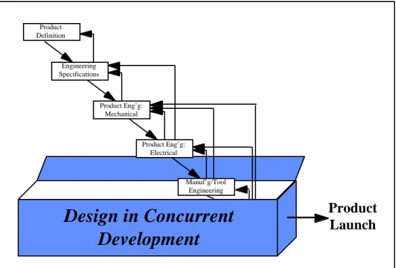
Engineering Specifications Product Eng’g: Mechanical Product Eng’g: Electrical Manuf’g/Tool Engineering Process/Launch Engineering Product Definition
Figure 1: "Over the wall” product development. Traditional methods of engineering design employed little coordination between upstream and downstream tasks, leading to the need for considerable backtracking and rework in the development process. (Adapted from Womack and Jones, p. 107)
2 . 3 . 2 The Separation and Integration of Knowledge
This highly iterative approach to design becomes inefficient for the development of complex systems. To develop such products requires that a wide and diverse set of skills be brought to bare on a problem. These skills tend to be beyond the grasp of any one individual, and, consequently, groups of engineers and designers must bring together their individual knowledge to
collectively solve a problem (Krishnan, 1997, p. 485). A critical issue in new product development, therefore, becomes the effectiveness with which engineers communicate.
As noted above, highly iterative methods tend to be inefficient at achieving such communication. This dilemma is an issue to which a substantial amount of research and literature is dedicated, and it is not the intent of this thesis to review it in detail. To understand set-based approaches, however, it is important to review several concepts in this area.
Gulati and Eppinger define three critical phases of communication: the availability of information, the transfer of that information, and the proper use and application of the information. They suggest, therefore, that not only must engineers exchange information, but that “it is important to assure that the correct information exchange takes place” (p. 14). But, as von Hippel (1990) notes, when problem solving extends beyond a single person, organizational and physical boundaries can degrade cross-boundary communication and coordination, reducing the effectiveness of engineers’ attempts to share their knowledge (p. 409). Thus, in addition to designing a product, a product development team must design its organization to facilitate the proper information flow.
This information flow is complicated, however, by what von Hippel (1995) defines as “sticky information.” Sticky information is typically in the form of tacit knowledge -- rules of thumb or guidelines -- which a person or organization takes for granted and would not necessarily think to communicate to others. Though von Hippel describes this theory in the context of a user or customer working with a manufacturer, the theory can also be applied to multidisciplinary design. In this context, the “user” is a downstream design process, such as production system design, and the “manufacturer” is an upstream process, such as conceptual design. Continuing the analogy, upstream design processes can be viewed as manufacturers of design information, and downstream design processes can be thought of as users of that information. To develop a product, however, requires the combination of both groups’ knowledge.
The difficulty posed by sticky information is that it limits the ability of two groups to effectively communicate, reducing the success of their combined efforts (von Hippel, 1995). The
27
problem is not that the two groups are unwilling to assist one another or that they do not possess the knowledge required for joint problem solving. Instead, the problem is either that one group may not realize that the other group possesses some needed knowledge, or that one group can not effectively communicate some knowledge to the other. The basic issue, therefore, becomes how to best transfer knowledge from one group to another.
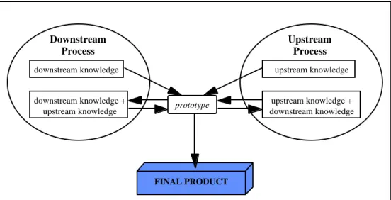
Von Hippel identifies four strategies to cope with the problem of sticky information, and these concepts can be adapted for use in a multidisciplinary engineering environment. The first two, upstream-based design and downstream-based design, are illustrated in Figure 2 and Figure 3, respectively. In upstream-based design, knowledge possessed by the downstream group is transferred to the upstream group. The upstream group then uses this knowledge along with their own to develop a design solution. To achieve this knowledge transfer generally requires that the downstream group (or a portion of it) be co-located with the upstream group, at least temporarily. Once the downstream group’s knowledge has been incorporated by the upstream group, the need for co-location ends. Downstream-based design is essentially the same, except in this case upstream knowledge is assimilated by the downstream process, which then manages the design effort.
Downstream Process downstream knowledge Upstream Process upstream knowledge + downstream knowledge FINAL PRODUCT
Figure 2: Upstream-based design. Downstream design knowledge is assimilated by the upstream design group, allowing the upstream group to possess all of the knowledge required to solve the design problem. (Adapted from von Hippel, 1995)
Downstream Process downstream knowledge + upstream knowledge FINAL PRODUCT Upstream Process upstream knowledge
Figure 3: Downstream-based design. Upstream design knowledge is assimilated by the downstream design group, allowing the downstream group to possess all of the knowledge required to solve the design problem. (Adapted from von Hippel, 1995)
A third strategy is iterative design, shown in Figure 4. In this strategy, the upstream group develops a prototype of a design, which is then sent to the downstream group. The downstream group experiments with the prototype, providing feedback to the upstream group. The upstream
29
group modifies the design and the prototype, which is again reviewed by the downstream group. The process continues until each group is satisfied with the design. Note that in this method, as opposed to the previous two, the location of the development work must switch back and forth between groups. This changing emphasis from one group to the other can result in waste, both in time and money, as design activities are started and then stopped at each group (von Hippel, 1995). Downstream Process downstream knowledge downstream knowledge + upstream knowledge FINAL PRODUCT Upstream Process upstream knowledge upstream knowledge + downstream knowledge prototype
Figure 4: Iterative design. The upstream design group first develops a prototype which the downstream group reviews and modifies. The process continues until both groups are satisfied with the design. (Adapted from von Hippel, 1995)
The final strategy is sub-problem design. Illustrated in Figure 5, this method decomposes the initial design problem into several smaller ones, each of which can be independently handled by either the upstream group or the downstream group. These independent solutions are then combined to form the final solution.
FINAL PRODUCT Downstream Process downstream knowledge Upstream Process upstream knowledge Sub-problem product Sub-problem product
Figure 5: Sub-problem design. The design problem is decomposed into smaller problems which each group can solve independently. (Adapted from von Hippel, 1995)
The decision as to which method to choose for a given project is based primarily on the costs and feasibility of transferring knowledge between the upstream and downstream groups (von Hippel, 1995). If this knowledge transfer is easy, a downstream- or upstream-based approach would most likely work best. When knowledge transfer is difficult, on the other hand, iterative or sub-problem design would provide the best strategy. These methods illustrate that the interactions between two design groups should be based both on the sequence in which their design work must be completed (upstream vs. downstream) and also on the ease or difficulty associated with transferring knowledge between the groups.
In a similar vein, Wheelwright and Clark define four modes in which upstream-downstream interactions might occur, illustrated in Figure 6. In mode 1, the upstream group does not communicate with the downstream group until it has completed its work, and the downstream group does not begin to do any work until it receives this communication. Mode 2 is similar, except in this case the downstream group makes assumptions about the upstream group’s work. The downstream group then begins its design process prior to actually receiving any information from the upstream group. Though this mode could be faster than the first, the downstream group runs a high risk of having to redo a significant amount of work if their assumptions prove
31
incorrect. Modes 3 and 4 increase the intensity of the communication between the upstream and downstream groups, and in mode 4 this communication occurs much earlier than in other modes. This final mode of interaction, mode 4, is the one which best facilitates the incorporation of upstream and downstream knowledge into a product’s design.
Mode 1 Serial/Batch upstream downstream batch communication Mode 2 “Early start in the dark” upstream downstream batch communication Mode 3 Early involvement upstream downstream intensive communication Mode 4 Integrated Problem Solving upstream downstream intensive communication
Figure 6: Modes of upstream and downstream interaction. Modes 1 and 2 permit little (if any) interdisciplinary problem solving between upstream and downstream groups, while modes 3 and 4 allow progressively greater interaction. (Adapted from Wheelwright and Clark, p. 178)
2 . 3 . 3 Transitioning to Concurrent Engineering
Based on these models of communication, it is clear that companies could improve their product development processes by facilitating better interactions between their upstream and downstream design groups. To this end, many companies have moved to implement concurrent engineering (CE) and cross-functional design teams.
Smith (p. 67-68) defines concurrent engineering in terms of four principles:
• an increased role for manufacturing process design in product design decisions;
• formation of cross-functional teams to jointly develop new products and processes;
• the use of lead time as a source of competitive advantage.
Hauptman and Hirji broaden this definition slightly, such that CE intends to address as many downstream issues as possible early in the design process: Concurrent engineering is “the integrated and parallel design of products and their related processes, including manufacturing, test and support” (p. 154). By facilitating such integrated design, concurrent engineering shortens development lead times. Note, however, that this decreased development time is not achieved by reducing the time required to complete design tasks, but rather by executing these tasks simultaneously (Hauptman and Hirji, p. 154). This reduction in lead time can be significant and represents a competitive advantage to those firms which can apply it well.
To facilitate CE, design organizations have moved away from the traditional functional configuration to adopt cross-functional design teams or integrated product teams (IPTs), illustrated in Figure 7. The primary aim of assembling such a cross-functional team is to enable a variety of perspectives to develop a product design concurrently, so that the final product is better integrated, and is developed more quickly and at a lower cost (Anderson; Krishnan, 1992; Pomponi). These interdisciplinary teams typically include engineers from upstream functions (such as design) as well as downstream functions (such as manufacturing). In addition, representatives from support groups such as marketing, test, finance, etc. also participate on the team (Anderson).
33
Team Leader
Design in Concurrent
Development
Marketing Tool Engineering Purchasing Product Engineering Process Enginering Manufacturing Product LaunchFigure 7: Design in the CE environment. In concurrent engineering, both upstream and downstream design groups simultaneously participate in the development of a product. (Adapted from Womack and Jones, p. 120)
Womack and Jones further characterize cross-functional, concurrent engineering and design as lean product development. They note that an ideal design process would operate much like a single-piece flow in a manufacturing system. Such an analogy suggests that in a lean development process, a new product design would move continuously from concept to production, without stopping due to bureaucratic needs and without backflow to correct mistakes (Womack and Jones, p. 119). As discussed earlier, a functional organization, with its strict separation of engineering specialties, often requires such backflow and rework. By allowing for direct communication between specialties, however, concurrent engineering moves closer to this continuous flow model. A product design no longer needs to be passed around to several independent engineering departments, but is instead worked upon by multiple engineers within the same team.
In terms of the communication models described previously, cross-functional teams and IPTs facilitate mode 4 interactions (integrated problem solving), and are a means of implementing upstream-based design (downstream groups are co-located with upstream groups). Many design
organizations also make use of prototypes during product development efforts, enabling cross-functional teams to use iterative design methods in conjunction with the other strategies. These cross-functional teams are, consequently, the key enabler in concurrent engineering: They bring together the individual knowledge of engineers required to develop a single, integrated design solution.
2 . 3 . 4 Interteam Communication: An Integration Problem
Typically, a cross-functional design team might be established to develop both a single product and its manufacturing plan. For more complex systems, the system itself might be decomposed, i.e., broken into several smaller elements, and an IPT assigned to develop each element. In such cases, not only must multiple skills be brought together within an IPT, but multiple skills must be brought together across several IPTs.
Under these conditions, the communication problem can viewed as an integration problem, i.e., how to integrate the knowledge of these multiple individuals or groups. Browning (1997) thus defines integrative mechanisms (IMs) as “strategies and tools for effectively coordinating actions between multiple” design organizations, such as integrated product teams (p. 86). These IMs have two primary purposes: to facilitate information flow and to regulate information flow (Browning, 1997). Examples of IMs include information and communication technologies (such as linked CAD tools and common databases), co-location, face-to-face meetings, manager mediation, and interface contracts and scorecards (Browning, 1997). Note that the goal of all of these methods and tools is the same: to help ensure that the right information is delivered to the right people at the right time and in the proper amount. These IMs are used to supplement the basic structure of the design team so as to further enhance the members’ abilities to share and combine their knowledge.
35 2 . 3 . 5 Task Sequencing
Despite the effort placed on integrated problem solving, concurrent engineering, and the associated design tools and methods, many problems in engineering design are coupled; that is, one design group is dependent upon information from another group (Krishnan et al., 1992). Examples of such coupling abound in the aerospace environment: in aircraft design, for example, engine selection is tied to wing design, while in spacecraft design, solar array sizing is linked to antenna size and power. In such cases, Group A might depend on Group B to provide data on variables x and y. Group B, however, might require information w and z from Group C. But, to provide this data, Group C might require Group A’s results (Browning, 1997, p. 83). Such interdependent, chicken and egg problems are difficult to sort out, because it is “rarely possible to identify an unambiguous sequence for making decisions” (Chang et al., p. 212). The concurrent environment previously described can, therefore, be thrown into disarray, while each engineer waits for information from other engineers.
To cope with these coupled design problems, many firms resort to a sequential decision making strategy (Krishnan et al., 1997, p. 485). Such strategies require that a design problem first be partitioned -- divided up -- into a “number of subtasks that may then be distributed among a number of individuals...[or] firms” (von Hippel, 1990, p. 407). Once a problem is partitioned, a tool such as a design structure matrix can be used to sequence the tasks to minimize the impact of iteration in the design (Browning, 1996). By properly sequencing tasks, the costs of downstream changes to a design can be minimized (von Hippel, 1990 p. 409).
The drawback of such tools, however, is that while they might minimize the extent of the changes which need to be made during an iteration, they may not help engineers determine the best sequence in which to make decisions (Krishnan et al., 1991). As decisions are made in series, choices made by upstream engineers will constrain the design options available to downstream engineers. Depending upon the nature of these constraints, the design quality of the product might suffer or the product might fail to meet requirements associated with downstream issues (Krishnan
to limit the extent of iterations, they should also initially sequence the decisions to limit the loss of design freedom by downstream designers (Krishnan et al., 1997, p. 488). By properly sequencing the steps in a design process, the coupling between problems can be reduced, allowing more effective use of other integrated problem solving techniques, such as the ones noted above.
2 . 3 . 6 Establishing Requirements in the Point-Based Approach and Doing It Right the First Time
To help cope with all of the difficulties associated with both integrating information across design groups and limiting the effects of iteration, conventional practice suggests that it is best to establish firm requirements early in the development process (Ward et al.). Requirements are finalized quickly to impose “as much constraint as possible in order to simplify the interactions among subsystems” and other members of a design team (Sobek, 1997, p. 224). The logic behind this approach is that since one design group does not necessarily know or understand the constraints faced by another group, each group must specify their subsystems in great detail to ensure their functionality and that they interface properly with other systems (Sobek, 1997, p. 224).
Therefore, conventional approaches to design, which rely on iteration to develop a product, lead to goals of freezing requirements and specifications as early as possible and philosophies of “doing it right the first time” (Ward et al., p. 48). This reliance, however, leads to two paradoxes. The first paradox relates directly to the development of requirements: System design methods emphasize establishing requirements early, but iterative methods imply that the requirements will change over the course of successive iterations (Ward, 1990, p. 50). Solving this paradox is not a simple matter. Flexible requirements, for example, run exactly counter to the idea of finalizing requirements early, yet allowing a firm requirement to change could invalidate previous design decisions (Ward, 1990). To facilitate iterative approaches to design, therefore, engineers and
37
managers continuously emphasize the need for firm requirements at the very start of a program, but must also be adaptable as the requirements change over a product’s development.
The second paradox relates to the very reason for initiating a development effort. Reinertsen states that “the purpose of a design process is to generate information” (p. 11). An efficient design process, therefore, is one which generates information cost-effectively. When developing a design, the feasibility and appropriateness of the concept is determined through testing, so to be cost-effective, each test should generate as much information as possible. When conducting tests, more information is contained in the results of a failure than in the results of a success (Reinertsen). A design process, therefore, does not maximize the amount of information which it generates by maximizing test success rates, but by ensuring “an adequate failure rate to generate sufficient information” (Reinertsen, p. 71). A philosophy of “do it right the first time” implies that a design would always successfully complete its development tests. Such outcomes, however, would not necessarily produce information in a cost-effective manner. The second paradox of iterative methods, therefore, is that a “do it right the first time” mentality actually decreases the cost-effectiveness of a design process by degrading the amount of information which the process produces.
These two paradoxes limit the efficiency and effectiveness of iterative design methods. While engineers and managers have developed many tools to aide in coping with these problems, current engineering methods do little to actually eliminate the sources of these paradoxes.
2.4 The Risks and Limitations of the CE Solution
While IPTs, IMs, task sequencing, and early requirements definition help to make CE approaches effective, working in a non-serial, concurrent environment still introduces additional risks to the development process. A CE-approach to product and process development “requires that the downstream phases be able to operate... using early upstream information” (Krishnan et
be finalized (Chang et al.; Krishnan et al., 1996). Changes which are made to this information, therefore, force changes to both the upstream phases providing the information and the downstream phases attempting to make use of it.
The continued reliance on iterative, point-based strategies, therefore, represents a limitation of current CE approaches to design. When multiple views are involved in developing a new product, each group will recommend changes to a proposed solution to better reflect that group’s constraints and requirements (Sobek, 1997, p. 201). This scheme of proposition and change, however, leads to several possible problems. Since each group in the design process does not necessarily understand the limits and needs of every other group, recommended changes can produce conflicts, leading to waste in the development process (Sobek et al., p. 16). Further, “the more tightly parts [of a product] are coupled to other components, the greater the impact changes in one component have on other components, and the more rapidly and pervasively such changes propagate through the system” (Liker et al., p. 170).
There is the potential, therefore, that a change made by one group in a design team could invalidate previous decisions made by other groups (Ward et al., p. 58). This potential for work to become obsolete tends to “deter simultaneous design” because engineers would rather wait to make a decision than have to redo their work (Liker et al., p. 165). Work that could be conducted in parallel then reverts to a truly sequential pattern, and the emphasis in project planning becomes the establishment of the proper sequence in which to make decisions (Liker et al., p. 167). Finally, there exist no guarantees that the iterative, point-to-point approach will ever converge on a final solution (Sobek et al., p. 7). Instead, the iterative loops are never quite closed, and, in the worst case, “problems are resolved when production begins, by selecting whatever last minute compromise is easiest” (Ward, 1990, p. 50).
39
2.5 Summarizing the CE Solution
Although concurrent engineering and IPTs have dramatically changed (and improved) engineering design, they have not significantly altered the nature of the design process. Non-CE methods were typified by one engineering group throwing a design over the wall to another group. What CE and IPTs have done is to “lower the wall:” upstream design groups now receive quick and extensive input and feedback on their design decisions from downstream organizations. But, as illustrated in Figure 8, within the team the nature of the design process has not changed: one group or person establishes requirements, another proposes a design solution, several others make comments about and recommend changes to the solution, etc. (Liker et al., p. 165).
Design in Concurrent
Development
Engineering Specifications Product Eng’g: Mechanical Product Definition Product Eng’g: Electrical Manuf’g/Tool EngineeringProduct
Launch
Figure 8: Looking inside the black box of CE. Looking inside the black box of concurrent design reveals that typical CE practices have simply moved feedback loops upstream in the development process, rather than altering the nature of the design process.
Rather than fundamentally altering the nature of engineering design, the effect of concurrent engineering and IPTs is to move engineering feedback loops upstream in the design process
(Sobek et al., p. 7), and to tighten and shorten these loops (Liker et al., p. 165). By decreasing the amount of time required for changes to circulate through a design team, CE- and IPT-based solutions aim to limit wasted time and effort spent pursuing designs which will not meet downstream requirements (Sobek, 1997, p. 226). The nature of the interaction between upstream and downstream groups, however, has not changed.
41
3.
Defining Set-Based Concurrent Engineering
3.1 Chapter Introduction
Concurrent engineering has improved product development processes significantly, but it has not altered the fundamental nature of the interactions which go on during that process. This chapter introduces the primary concepts of set-based concurrent engineering, and illustrates how set-based concepts have the potential to fundamentally change the manner in which engineers interact.
The chapter begins by introducing several concepts which suggest why making decisions early, a core tenant of point-based methods, is not always the best strategy in product development. The principal concepts of set-based concurrent engineering are then summarized, followed by a more detailed description of those concepts. Other design methods which support the use of sets are then discussed, as well as how these methods, though different, are compatible with set-based concurrent engineering. The chapter concludes by summarizing the principles of set-based concurrent engineering, providing the foundation for the remainder of the thesis: examples of set-based practices and how set-based concurrent engineering could be applied in the aerospace industry.
3.2 The Triple Problem: Factors Motivating the Need to Delay Decision-Making
In addition to the challenges posed by attempting to work in a concurrent environment, design is complicated by three other factors: the evolution of a product’s cost, management’s ability to affect these costs, and the evolution of designers’ knowledge about a design problem. As
will be discussed, these factors all lead to a direct conflict with traditional concepts of design: Rather than making decisions as early as possible, there are advantages to making decisions as late as possible.
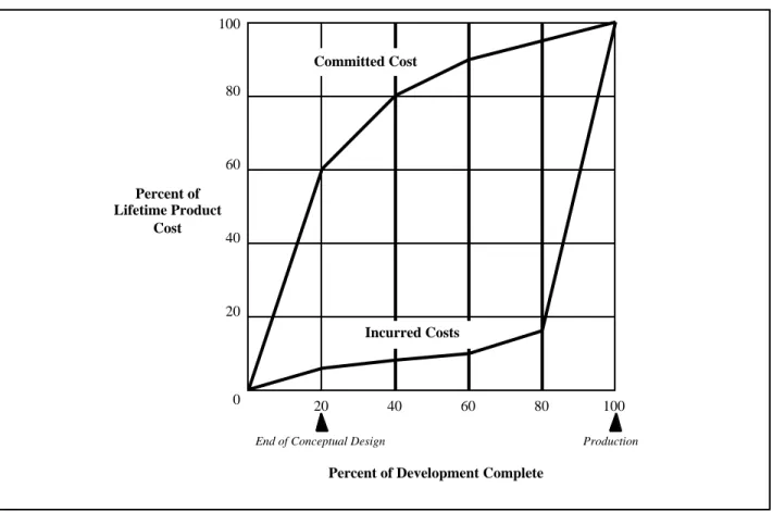
Consider first the issue of a product’s cost. As a new product is designed, engineers will make decisions affecting how much the product will cost: how expensive it will be to manufacture, for how much it will have to be sold in order to earn a profit, how much the product will cost to support and maintain, etc. The difficulty associated with these decisions, however, is that “[t]he earliest decisions about designs have the largest impact on the ultimate quality and cost, but these decisions are made with the least data” (Ward, et al., p. 59). As shown in Figure 9, sixty percent of a product’s total life-cycle costs have been designed into the product by the end of its conceptual development -- even before preliminary or detail design has begun (Anderson, p. 133). Thus, decisions made very early in the product’s development will have long-lasting consequences on the total cost of the system, while decisions made late in its development will have little success in lowering these costs (Anderson, p. 230).
43 100 80 60 40 20 Percent of Lifetime Product Cost Committed Cost Incurred Costs 0
Percent of Development Complete
20 40 60 80 100
End of Conceptual Design Production
Figure 9: Designing-in costs. Although the majority of the costs associated with a development program are not incurred until late in the project, costs are committed to the product’s lifecycle very early. (Adapted from Anderson, p. 132)
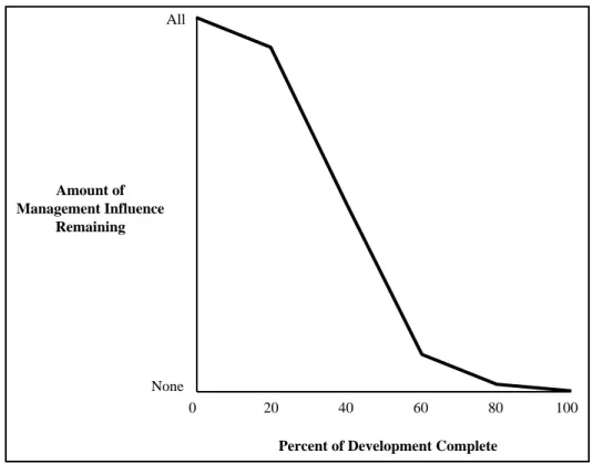
This problem becomes even more difficult when one considers management’s ability to influence a product’s design. As illustrated in Figure 10, management can exert its greatest influence on a product early in the development cycle. As the cycle progresses, however, this power is greatly diminished (Wheelwright and Clark, p. 33). In addition, the costs associated with making any changes to a product’s design rise exponentially during the design process (Reinertsen, p. 14). As Anderson summarizes, “The further one progresses into a design, the
harder it will be to start satisfying additional needs” (p. 229). This trend appears because every
decision made by engineers constrains the options available for future decisions (Anderson; Krishnan et al., 1991). Thus, late in the design process, engineers have already made numerous decisions, severely limiting the alternatives available at that time. As a consequence, not only do
early decisions have long-term effects on a product’s costs, but management’s power to influence these costs declines rapidly as the product develops.
Amount of Management Influence
Remaining
0
Percent of Development Complete
20 All
40 60 80
None
100
Figure 10: The diminishing power to make changes. The further a development project progresses, the less power both managers and engineers will have to influence its final outcome. (Adapted from Wheelwright and Clark, p. 33)
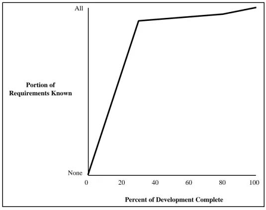
These factors conspire to make early design decisions more powerful than later ones. But they are further complicated by yet a third factor: lack of knowledge. As shown in Figure 11, early in a product’s development (such as during conceptual design), engineers’ and managers’ knowledge about virtually every aspect of the product will be at a minimum (Reinertsen, p. 15). Their early decisions, therefore, will be relatively uninformed. As they “work the problem” and become more familiar with the constraints which they face and better understand the customer’s needs, they will be able to make better design decisions. But, as was just discussed, it is the early decisions which will have the most dramatic effects on the long-term costs of the product.
45
Engineers and managers, therefore, are placed in the awkward position of having to make high-leverage decisions with very little knowledge.
Portion of Requirements Known
0
Percent of Development Complete
20 40 60 80 100
None All
Figure 11: Evolution of design knowledge. Though it increases fairly rapidly, designers’ knowledge about a new product is quite low early in the product’s development. (Adapted from Reinertsen, p. 15)
In summary, early decisions have the greatest effects on a product’s costs, yet these decisions are based on the least information. When engineers and managers have acquired the knowledge to make better informed decisions, however, their ability to significantly affect the product’s costs is severely limited.
As shown in Figure 12, a useful advance in product development practices would either delay the commitment of these costs until greater knowledge was available or would increase managers’ ability to affect the design late in the process. (This proposition assumes, of course, that one cannot know the future, and therefore, cannot increase the rate at which knowledge about the new product becomes available.) In fact, Kalyanarum and Krishnan go so far as to suggest
that an ideal development program would enable designers to adapt a product to current market realities at the time of the product’s launch (p. 277). They note additional benefits of such delayed decision making would include:
• allowing the product to achieve a better balance between what the customer desires and
what is technically feasible;
• allowing for the inclusion of the latest technology; and
• allowing competitive products and changes in customer desires to be better tracked
(Kalyanarum and Krishnan).
While point-based strategies have continuously emphasized making decisions as early as possible, it is clear that there are equally valid reasons to delay decision making.
100 80 60 40 20 Management Influence Committed Costs 0
Percent of Development Complete
20 40 60 80 100
Knowledge (not changeable)
Figure 12: Advancing product development practices. Useful advances in product development practices would help to both delay the commitment of costs to a product and to increase management influence late in the development cycle.
47
3.3 The Need for a Paradigm Shift
The intent of concurrent engineering has been to increase the influence of downstream groups on upstream design decisions and to improve the quality of critical, early design decisions. In an ideal environment, concurrent engineering also intends for downstream groups to work simultaneously with upstream groups. The reliance of point-based methods on iterative techniques, however, increases the risks associated with this parallelism. In addition, iterative methods lead the paradoxical situation of needing to establish requirements early, yet knowing these requirements are likely to change as iterations are completed. They also seek to develop a design “right the first time,” though such an approach is not necessarily cost-effective. Finally, point-based approaches require that decisions be made as early as possible, even though there can be benefits to delaying design decisions. As Liker et al. note, “Full implementation of CE involves a corresponding revolution in the underlying paradigm of design” (p. 165). Set-based concurrent engineering is offered as such a paradigm shift.
3.4 Set-Based Concurrent Engineering Defined
3 . 4 . 1 An Introductory Summary
Sobek (1997) summarizes the definition of set-based concurrent engineering (SBCE) as engineers and product designers “reasoning, developing, and communicating about sets of solutions in parallel and relatively independently” (p. 202). This definition is best understood by analyzing it one piece at a time. The first component of SBCE is to develop sets of designs, i.e., groups of design alternatives, for a given design problem. Rather than trying to identify one solution, engineers should instead develop a variety of design options, and then gradually eliminate alternatives, until only one option remains.
The second component of SBCE involves inter- and intra-team communication for concurrent engineering. Given that a complex design problem will require the involvement of multiple engineers or functional groups, SBCE suggests that these groups should each develop sets of solutions to the problem from their own perspectives. The groups then interact by comparing these sets, looking for regions of overlap in their design alternatives. These regions of overlap are then narrowed in parallel, until one solution remains.
By using sets, therefore, engineers are able to implement a design strategy very nearly akin to von Hippel’s sub-problem design. As was noted during the discussion of von Hippel’s work, sub-problem design is best suited to design problems in which it is difficult to share knowledge between groups. The knowledge possessed by highly specialized engineering functions often has this characteristic, and, therefore, sub-problem design is an appropriate strategy. Independent exploration of design sets enables several engineering specialties to consider a design problem from their own perspective (i.e., to allow each specialty to work on a sub-problem) and then to effectively re-combine those independent alternatives into an integrated final solution. These concepts are illustrated in Figure 13, and the following sections will explore these ideas in greater detail.
49
TIME
Specialty 1 Specialty 2 Specialty 3 Design Space(1)
(2)
(3)
(4)
(5)
Intersection of independent solutionsFigure 13: Set-Based Concurrent Engineering. (1) Three specialties, or functional groups, are illustrated within the design space (which contains all possible solutions) for a product development problem. (2) First, the specialties expand the number of options which they consider, establishing a small region of overlap between their design solutions. (3) They work together to expand this region of overlap, increasing the number of solutions which will satisfy all of the product’s requirements. (4) The specialties then begin to eliminate options, and the region of overlap shrinks. (5) The solution space then is narrowed until only one design remains, that design being the final solution. (Illustration concept developed with Dr. William Finch.)
3 . 4 . 2 Developing Sets of Alternatives
As noted, the first element of SBCE is the development of sets of alternative solutions for a design problem. These sets might include several discrete design options or a range of parameter values (Liker et al., p. 167). For example, a set might consist of one aircraft design based on a