by
JIAZHEN FANG
Bachelor of Professional Studies State University of New York Buffalo, New York
1984
in Architecture at Buffalo
Submitted to the Department of Architecture in Partial Fulfillment of the Requirements of the Degree
Master of Architecture at the
Massachusetts Institute of Technology February 1987
©Jiazhen Fang 1986
The author hereby grants to M.I.T. permission to reproduce and to distribute publicly copies of
this thesis document in whole or in part
of
Signature of the Author...
Jiazhen Fang Department of Architecture December 16, 1986
Certified by...
Assistant Prof
Accepted by... ... ... .. .. z...\
... Frank C. Miller essor, Computer Aided Design Thesis Supervisor(Jtd7.DaDaylon /Mitchell
Chairman
Departmental Committee for Graduate Students
MASSACHUSETTS INSTITUTE OF TECHNOLOGY
FER 2 5 1987
u
I
n
DECISION SUPPORT FOR WINDOW DESIGN:
- A Computer-based Prototype by Jiazhen Fang
Submitted to the Department of Architecture on December 31, 1986, in partial fulfillment
of the requirements for the Degree of Master of Architecture.
ABSTRACT
Several approaches have emerged for the integration of computer aided design support systems and architectural design processes. However, architects have yet to see such a system that is not only useful for producing construction drawing, but also useful in earlier processes of the design, for example, in the preliminary design stage, in the use of architectural referencing, and in evaluation of alternative design solutions.
The design support system that I propose and implement in this thesis, is one that incorporates traditional design tools with computer technology. The system is capable of evaluating designer's decisions and automatically translating his or her decisions to a 3-D model; it provides the designer with an interactive means to access visual images and textual data; it is also, much like the knowledgeable expert, capable of evaluating and manipulating the form, and engaging the designer in constructive discussion about the form until he or she is most satisfied with it.
Acknowledging the challenge of implementing such a system in a complex design environment, this thesis focuses on a small prototype model. The prototype model illustrates all the issues that I have presented and implies a much broader structure that future implementation work can be expanded from. The system is called LWINDOW - a prototype design support system for designing library window. The thesis addresses three major issues, i.e. the idea and rationale behind such a system, the implementation strategies and examples, and lastly, the evaluation and future trends.
This thesis aims to contribute to the development of computer aids for the preliminary phases of design. I hope
that as a result of this prototype design support system, the environment of the integrated design support system for architects will no longer be something the experts talk about, but will become a realistic system that can eventually aid architects in their every day practice.
Thesis supervisor: Frank C. Miller
ACKNOWLEDGMENTS:
To Professor Frank Miller, my friend and thesis advisor, for his ins'piration and help in developing and following my interest. Without his insightful advises, none of the issues in this thesis would have been in focus.
To Mr. Roman Budzianowsky of Project Athena, for always making himself available to help me solve any technical difficulties, offering helpful criticism of my work.
To Professor Patrick Purcell, for introducing me to the medium of videodisc and intriguing me with its complexity and potential.
To Mr. Yoav Etiel of Architecture and Computer Aids Ltd, for mialing Solid Vision available for our research, and several special trips to the lab for instruction and insightful comments on my work.
To all those who cannot be named, for all the favors and extra efforts that make it possible to get things accomplished.
To my family and relatives, for their patience, unquestioning support that help my through the longest process.
TABLE OF CONTENTS ABSTRACT...2 ACKNOWLEDGMENTS... ... ... .. .44... TABLE OF CONTENTS...5 CHAPTER ONE INTRODUCTION. Section Section Section 1. The Design 2. LWINDOW: a 3. Components of LWINDOW Process: A Hypothesis Set of Linked Programs and Configuration
CHAPTER TWO
KNOWLEDGE AND GRAPHICS: Link Between Knowledge Based
System and Computer Aided Design System...14 Section 1. Limitations of Current CAD Systems
Section 2. a Brief Description of Solid Vision Section 3. Implementation of LWINDOW
with Solid Vision and KES CHAPTER THREE
KNOWLEDGE AND VISUAL REFERENCES:
The Use of Visual References by Architects...20 Section 1. Section 2. CHAPTER FOUR KNOWLEDGE BASED Section 1. Section 2. Section 3. CHAPTER FIVE A SAMPLE DESIGN CHAPTER SIX
a Brief Description of INGRES and Optical Videodisc
Implementation of LWINDOW with INGRES and Optical Videodisc
SYSTEM FOR LIBRARY WINDOW DESIGN...24 Knowledge Based Systems
A Brief Description of KES Implementation of LWINDOW with KES
3.1 Attributes 3.2 Rules
3.3 Inference Strategies and Control
SESSION WITH LWINDOW...36
APPENDICES... Appendix Appendix Appendix Appendix Appendix 1 2 3 4 5 ... .. ... . . .. ... 59 LWINDOW Knowledge Base
Kes arcO Arc kes1 Kes arc2 Ing-vid
CHAPTER ONE
INTRODUCTION
Section 1. The Design Process: A Hypothesis
Design processes vary widely between architects as do their buildings. While not attempting to conduct an overview of design theory, I think it may be worthwhile to consider some observations of the design process by some well-respected scholars before describing my own working assumptions.
Let us consider a range of definitions, such as "goal-directed, problem-solving activity" (Archer, 1965); or "conscious effort to impose meaningful order" (Papanek, 1972); or something purely mythical: "The performing of a very complicated act of faith" (Jones, 1966). But as I view it, the design process can seldom be predicted and neither should it be defined in any "generic way". M.L. Minsky warns those theoreticians that: "...design is a notably obscure kind of problem-solving. There is little use to read opinions of the Masters on how they achieved success; their theories are almost as diverse as the psychologists, and almost as inadequate!" (Minsky, 1967) History in the development of design theory suggests
clearly that as soon as someone comes up with a definition about it, it tends to seem static and over constraining. (Christopher Alexander's disapproval of his own early theory of design process is just one of many examples). My thesis proposes a model of a design support system to
aid architects while designing. With this design support system, I am making some assumptions about the design process and presenting a personal view of how a design support system can be structured using currently available technologies. I will also discuss how such a system can acknowledge and respect the creative and unpredictable nature of the design process, and allow for optional decisions by architects in their design process.
My hypothesis about the design process is based on activities which may occur while designing. "The emphasis is on the concept of a 'process': a sequence of many different kinds of activities" (M.L. Manheim, 1976). The design support system is essentially composed of a set of
linked computer programs, to some extent not dissimilar to
traditional design tools, that facilitates those activities in the design process.I will focus on three major categories of activities that frequently occur in the design process. They are:
1. Transformation and manipulation of form sketching, building models, quick renderings, etc.);
(i.e.:
2. referencing visual, formal and textual information (photographs, slides, maps, drawings, site visits or field trips, etc.);
3. expert consultation (i.e.:structural or electrical consultation, user/client need consultation, and so on) We can find a close analogy between the traditional design
tools and computer tools made available in recent years by electronic technologies(see Figure 1.1). Both media can be seen as integral part of and have direct impact on the design process. They may be used in parallel, iteratively,
or to supplement one another.
DESIGN TRADITIONAL COMPUTER
ACTIVITIES: DESIGN TOOLS COUNTERPARTS -Design and manipulation Paper, pencil, Computer aided
of form; cardboard, design (CAD)
etc.
-Referencing visual and Magazine, Visual informa-textual information; slide, book, tion system (VIS)
etc.
-Expert advice and Consultant, Knowledge based
consultation instructor expert system
etc.
Figure 1.1 - Traditional
and computer design media
The integration of these computer tools to form a model for the design support system is demonstrated in a prototype system called LWINDOW. The details of its concept and the implementation strategies will be presented in the following chapters.
Section 2. LWINDOW: a Set of Linked Programs
Library Window Design (LWINDOW) is a interactive set of computer programs to aid architects while designing windows for a library. It is a system developed with special attention to incorporate designer's knowledge and awareness of design process. Moreover, it is a prototype design support system implying a much larger general-purposed integrated design environment.
Primary features of the system include:
- keeping the designer in close contact with the problem solving process as a consultant or a knowledgeable colleague;
- involving and helping the designer to understand his or her decision (telling the designer if he or she breaks the rule, and providing the designer optional ways either to fix it or ignore it);
- most of the program is easily modifiable, adaptable to new needs and even replaceable, partially or in whole, by more suitable program of their kind for unpredictable
future needs.
- it aims to avoid conflict with the traditional design process, and supplement it with more effective and efficient means via "optional paths through a pluralistic media environment" (F.C. Miller, 1986);
- it is a rule-based knowledge engineering system using hierarchical relationships and rules between various attributes to reach one, or several possible alternatives to a design problem;
- all the subprograms in LWINDOW are modulized and linked together, and they ultimately form an integrated design supporting environment.
Section 3. Components and Configuration of LWINDOW:
The working hypothesis about the design process is essentially about finding and solving problems, which requires knowledge, expertise and the interactive tools. With that concern, the entire program of LWINDOW evolved from a intelligent and substantial knowledge base, using a
rule-based expert system shell language KES (refer to Chapter Four for details)
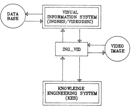
VISUAL INFORMATION SYSTEM (INGRES/VIDEODISC) _I7 KNOWLEDGE ENGINEERING SYSTEM (KES) COMPUTER AIDED DESIGN (SOLID VISION)
Figure 1.2 - Schematic diagram of LWINDOW
A knowledge base can most effectively be constructed by a knowledge engineer in cooperation with the user-designer. It requires not only the programmed knowledge base be able to perform sophisticated problem-finding and problem-solving tasks, but also the program itself be easy enough to understand, create and modified by the designer without much difficulties. KES is exactly a program of that type, both sophisticated in its ability and it comprehensive
KES is also capable of accessing other program(s) in the environment at any time for reasons such as visual representation, historical reference or technical data etc.
Here the need for a Visual Information Systems (VIS) become evident. The VIS facet of LWINDOW contains much visual /textual information about the design of library window design which the designer would select, for whatever reason, to be relevant to one's design.
The data base is linked to KES dynamically, so whenever and wherever the designer is in KES environment, one can access to VIS and DBMS for explanation, clarification or stimulation. It is also able to perform tasks such systematic search, random search and inferred search
(refer to Chapter Three for details).
Designer deals primarily with form, so the environment must include graphic software and hardware that are capable of creating graphics generally better, faster and more precise than its human counterpart, if it is so desired. In the case of LWINDOW, Solid Vision is selected in its implementation (refer to Chapter Two for details). The output of the image data is used to communicate with KES for evaluation and manipulation, which can happen in almost any stage of the process.
Following softwares are used or developed in the LWINDOW: -Knowledge Engineering Systems (KES) version 2.2 by Software Architecture and Engineering, Inc.;
-Interactive Graphics and Retrieval System (INGRES) version 3.0-VAX/UNIX by Relational Technology Inc.;
-SOLID VISION version 2.03 by Architect and Computer Aids Ltd;
-C and UNIX C shell programs by the author (see Figure 1.3).
The hardware utilized in the system includes:
-IBM-AT personal computer networked to VAX 750 running UNIX (version 4.3) operating system;
-Sony videodisc player model LDP-1000A;
-Panasonic color video monitor model CT-1350MG (see Figure 1.4).
Chapter two will explain in great length the graphic subprogram of LWINDOW, which will then lead to the discussion of visual information System and Knowledge based System in the chapters to follow.
CHAPTER TWO
KNOWLEDGE AND GRAPHICS:
Link Between Knowledge Based System
and Computer Aided Design System
Section 1. Limitations of current CAD Systems:
The explosion in the of use of CAD programs makes it conceivable that coming generations of architects will apprentice on computers in addition to drafting tables. This has been made possible by the development of faster, less expensive and more reliable CAD packages. But most of these packages are developed and used for design production or drafting. In order for them to be useful in the earlier phases of the design, they must be developed with an understanding of the designer's decision process, and capable of translating the decisions to visual form. The next logical step in their development is to develop the link between knowledge and the graphical tools. The success of such a link will allow the automatic translation of the designers' knowledge and decision to 3-D form. This thesis presents one model for this type of systems, which is not only capable of understanding designer's decision and generating graphic models automatically, but also evaluating and manipulating graphic model in the process of formulating alternative design decision. How this kind of system can be designed and implemented is explained in this chapter. The full implemented program in action is presented in the last chapter of thesis.
Section 2. a Brief Description of Solid Vision:
The CAD software used for this exploration is version 2.03 of Solid Vision developed by Architecture and Computer Aids Ltd. of Israel. It is viewed as one of the promising and technically superior architectural design computer
systems available on personal computer to date.
Solid Vision is a powerful three-dimensional solid modeling design system capable of drawing, revising and manipulating the graphical model with reasonable speed on an IBM-AT. It can create geometrical model as well as solid and surface models, which enable the system to represent the graphic model in perspective, axonometry, cast shadows, and produce successive views of the model from different positions.
The process of editing the model is essentially in a series commands, command-like macros, or optionally menu-driven user input. The saved drawing is stored in
the form of data base in machine code or ASCII characters if the user specifies so.
While Solid Vision is commercially available, this thesis utilizes a pre-release version which includes some undocumented commands.
Section 3. Implementation of LWINDOW with Solid Vision and KES:
In addition to the superior modeling capability that Solid Vision has, one feature worth mentioning again is the structure of the database extract file or dump file (see Figure 2.1). \ENTITY 30 ENT 2069 ADDR 76 LEN 12886 DATE 1 LYR 1 APP 1 INDI 4 GEOM 0 ADDRE 0 LENE \DATA 0 LTYPE 0 COLOR 0 WIDTH 0 ** Figure 2.1 -Wopen ELEM 1.0001
0
0 0 0 0.3040
0 0 0 1.0001 0 0.80
0.8 1 \endAn example of a dump file of a wall opening and a 3-D model showing four of them in a room
The 3-D model generated by Solid Vision can be both in graphical form or in an ASCII "dump file". The advantage of which is that, with the readable and accessible data structure, the graphical data can be retrieved and made useful for communication with other application programs. Since the data symbolically records the the model in a non-graphical way, the same set of data can be evaluated or modified as if it is the model itself, and the result of evaluation and modification to the data can have automatic impact on the image, when it is regenerated on the screen (see Figure 2.2). By the same token, some external programs, perhaps non-graphic program(s), can create the similar data and send it to the Solid Vision for image generation, as long as the data is conformed to syntax and the data structure of Solid Vision.
My work then is to study the structure of Solid Vision data base, and try to have some understanding of what each numerical data represents. This involves more of lengthy test-and-error kind of scrutiny, back and forth between graphic and text editor than I first expected, because of the shortage on documentations concerning the data convention and data structure. With some helpful suggestions from my colleagues, I find it is much easier and more straight forward to create the graphic data by command-like batch file, or macro, than create Solid Vision-like data and data structure for image generation. That is exactly what I have done for the initial link between KES and Solid Vision (see Figure 2.3).
Figure 2.3 - Generation of a 3-D model via a batch file
Inevitably, a external program must be designed to perform the linking task. It takes the relevant data from one data file according to some predefined criteria and format it as a input file for the other program to read in. The success of the program is determined by how smooth and how fast the data is communicated between the two programs.
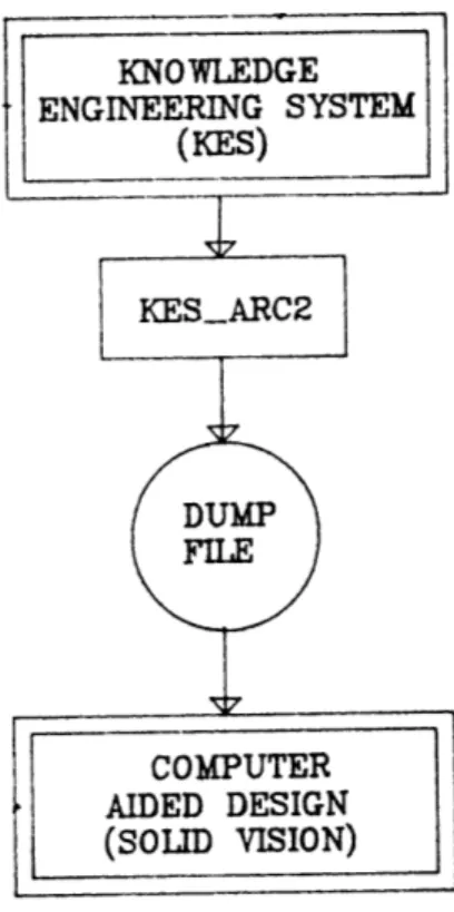
KES generates an output data file according to user's input and its own built-in inference engine, and the data file can then be formatted into a Solid Vision batch file by the external or intermediate program called "KESARCO" (see Appendix 2 for source codes). Solid Vision in turn generates automatically the image on the graphic screen for user's observation and possible modification.
There are two possible activities can happen, one is that the user may like to change the image directly on the screen and send the result of changes back to KES for comments, or the user may want to go back to KES without changing the image, and input another set of data in KES for Solid Vision to generate more image(s). The later case is just as straight forward as it seen, but in order to have the computer to perform the first type of scenario, another piece of link must be developed . What the link program will do is to save all the changes the user made and sort out only those relevant data into a file readable by KES (see Appendix 3 for source codes). Notice the communication between KES and Solid Vision now becomes two-way, and this two-way process can go on as long as, or as short as, the user wants it to be, possibly until the result become satisfactory.
What we have seen now is the process of translating rules about design into the representation of a 3-D model, and with the change of the visible model, it is then tested against the rules for further modification or refinement. This process goes on interactively. The link program makes process as automatic as it can possible be. It also demonstrates to us that, in fact, the automated design CAD system is accomplishable and the realization of process-orientated graphic system is within the reach (see Figure 2.4).
Figure 2.4 - Two-way communication between KES and Solid Vision
CHAPTER THREE
KNOWLEDGE AND VISUAL REFERENCES:
The Use of Visual References by Architects
"'Pictures are worth a thousand words'. The dictum still holds good in the world of computer graphics..." (P.A. Purcell, 1986).
Effective design environments are rich in reference and information. In almost any design process, it is not unusual to see the architects gather together many photographs, plans and sketches for formal referencing and visual stimulation.
But as the number of images grow, the architects need strategies to manage, store and retrieve those images. Typically, the architects have to work with fewer images than they would like due to the cost of maintaining and time of accessing them. With the development of Visual Information Systems and large volume storage devices such as optical videodisc, the number of images that can be make accessible to the architects become virtually limitless, and retrieval speed become almost instantaneous.
There are basically three ways to search visual and textual information:
1.random searches: one has only general ideas as to what is being looked for, and depends on intuition to randomly browse through available sources (like reading newspapers, one generally is not looking for anything special, but rather letting whatever is on the paper inform or stimulate one's thought);
2.Indexing search: one have some initial idea or key word of what one is searching for, and looking through systematically the relevant materials and gradually find the information one wants (kind of like looking through card catalogues in a library);
3.inferred search: in this case, the wanted information is generally not the result of one's direct search, but rather inferred by the results of design processes or other related information which suggests or make references to it.
The visual information system of LWINDOW incorporates all type of searches mentioned above, so it uniquely makes all the information on the disc accessible in whatever mode of search one uses. With the system, all the image are always readily accessible at one's finger tips.
This chapter deals with the VIS facet of LWINDOW. It takes the advantage of the new development of optical videodisc technology and data base management system, and link them with a knowledge based system to form a integrated Visual Information System. This chapter presents how this kind of system can be designed and implemented, and the full implemented program in action will be shown in Chapter Five of the thesis.
Section 1 A Brief Description of INGRES and Optical Videodisc:
The DBMS software used for implementation of LWINDOW is called INGRES. INGRES (Interactive Graphics and Retrieval System) is a relational database system which runs in the UNIX operating system. INGRES is primarily written in C, a high level programming language in which UNIX itself is written.
INGRES offers, in addition to all the advantage provided by the nature of relational data structure, the high degree of data independent, and a high level and entirely procedure-free facility for data definition, retrieval, update, access control, and most of all, dynamic communication with other program and programming languages.
The optical videodisc is an extremely dense and versatile storage medium for picture, text and sound. A single twelve-inch disc can hold approximately fifty-five thousand images (at 80 slides per carousel tray, this is the equivalent of 675 trays of slides), or half hour of video, or almost 800 megabytes of data (that is equivalent of twenty sets of a twenty-volume encyclopedia).
The image stored on the disc can be played on the discplayer to show them individually or in motion. But all of that can only be done manually via a push-button control unit if without some forms of external support. Its content, in fact, can only be fully explored and used most effectively when it is linked to a computer and appropriate data and supporting programs. All items on
the disc then become immediately accessible, in any order or in various combinations with referencing frame numbers. In the process, the computer-linked videodisc becomes an powerful tool capable of handling vast amounts of information in ways and with a speed impossible by and other means. It holds evidently the potential to revolutionize image storage and accessing systems for architectural profession.
Section 2. Implementation of LWINDOW with INGRES and Optical Videodisc:
Visual information system (VIS) of LWINDOW consists of INGRES data base, optical videodisc, and some sort of user interface utilities and image interface routines developed specially for this project.
INGRES is a successful program in terms of handling database management facet of LWINDOW, however the format it presents the output is always in the form of table, and the somewhat cumbersome command, lengthy menu, and limited user interface make it an less desirable environment for the designer. In order to eliminate that restriction and enhance its user interface, I think, an external program must be developed to tailor it down to our special need. So the user may access the INGRES via an intermediate program, in fact the user is not even required to know anything about INGRES syntax, or rigid rules on moving
from tables to table and menu to menu, to run INGRES.
Another task the intermediate program is capable of performing is to provide link between the INGRES database and the optical videodisc, so the image can be displayed automatically upon information given by INGRES or the user (see Figure 3.1).
Each image has information associated with its frame number. And the data is stored in form of INGRES table. The data can be changed directly by the user during the execution of interface program. The advantage of that is the user can record on the data base, in addition to what is already in the data base, one's personal thought about the image for future reference, so as the program is used more and more, the data base grow also and each table contains more complete description of the video image it associates with.
search in the database, if it find any information that is relevant to the query, it will present the data in the table(s) first, and ask weather the user want to see the associated image, if the user specifies yes, the image will be shown on the video screen as well as its selected data on the monitor simultaneously. The user then has the options of either sequentially back and forth viewing the retrieved images, or go into random browsing mode, which practically allows the user to view any 55,000 images on the disc at one's will.
CHAPTER FOUR
KNOWLEDGE BASED SYSTEM FOR LIBRARY WINDOW DESIGN
Since World War II. computer scientists have tried to develop techniques that would allow computers to reason more like humans.
The computer was originally built mainly for numerical processes (i.e. "1+", "-" and ">" as opposed to logical processes, such as "and", "or" and "not"), but computer scientists tried to explore the ability of computers to manipulate non-numerical symbols. Simultaneously, psychologists concerned with human problem solving sought to develop computer programs that would simulate human reasoning. Over the years, individuals concerned with both symbolic processing and human problem solving have formed that interdisciplinary subfield of computer science called artificial intelligence (AI).
In the 1970's, the development of microelectronics technology resulted in a new generation of faster, more powerful, and relatively inexpensive computers. Joining hands with this new technology, the impact of AI on every profession and its contribution to the extension and effectiveness of human capability is never considered possible. Fast, multi-processing, multi-tasking and networked computing environment, combined with significant theoretical advances in AI, has resulted in a technology with increasing potential.
Section l.Knowledge Based systems:
Edward Feigenbaum, one of the leading researchers in expert systems, has defined an expert system as:
... an intelligent computer program that uses knowledge and inference procedures to solve problems that are difficult enough to require significant human expertise for their solution. Knowledge necessary to perform at such a level, plus the inference procedures used, can be thought of as a model of the expertise of the best practitioner of the field.
Knowledge based systems are knowledge-intensive computer programs. They primarily use rule-based techniques, statistical analysis or hypothesis test cycles to reach some sort of decision or alternatives to a given problem. They contain lots of knowledge about their specialty. They use rules to focus on the key aspects of particular problems and to manipulate symbolic descriptions in order to reason about the knowledge they are given. The successful systems can solve difficult problems, within its designed domain, as well as or better than human experts can.
Knowledge-based systems are highly interactive. A user can halt the processing at any time and ask why a particular line of questioning is being pursued or how a particular conclusion was reached. In addition, the knowledge base of an expert system is readable and easy to modifiable by a knowledgeable user, because the system is constructed by
somebody like him, or could very well be by the user with some self-instructive training.
All this is not to suggest that most of today's knowledge-based systems are as good as human experts. The technology is new and the system is commonly confined to well-circumscribed task, for example, it is not able to reason broadly over a field of expertise other than itself.
Section 2.A Brief Description of KES:
The expert system shell used for the implementation of LWINDOW is a rule-based module of Knowledge Engineering System (KES), version 2.2. It is a product of Software Architecture and Engineering. KES is expert system development environment that support the designing of
consultation-style knowledge systems.
Facts in KES are represented as attribute-value pairs with associated confidence factors, or probabilities. Attributes and values can be arranged in hierarchies. Relations among facts are represented as production rules, using statistical pattern classification techniques, or with hypothesis test cycles.
Control is maintained by the inference engine with statements following keyword "actions", which are essentially a series of commands and conditional statements that direct users through the inference
process.
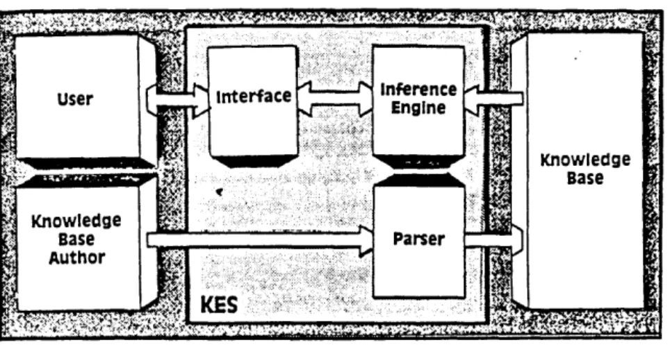
Users communicate with KES through a line-oriented interaction. Multiple-choice questions provide a list of alternatives. Explanation facilities are available to define terms and explain reasoning at users' request.
The major components of KES and their illustrated in Figure 4.1.
interrelations are
Figure 4.1 - Diagrammatic configuration of KES
Section 3.Implementation of LWINDOW with KES.
The LWINDOW knowledge-base program can be divided into two parts, i.e. the knowledge base and the working memory constitute one part of the system, and the inference engine and all the subsystems and interfaces constitute the second part. The knowledge base contains the facts and rules the embody the expert's knowledge, whereas the inference engine contains the inference strategies and controls that an expert uses when he or she manipulates the facts and rules.
Subsection 3.1. Attributes:
Considering the problem of deciding the height of the sill. Sill height is a extremely sensitive dimension the designer may like to consider in the early part of design. There are many consideration and facts have to be taken into account, a brief list of related items are presented bellow:
l.privacy of room;
2.view from inside to outside;
3.view from outside to inside; 4.view position;
5.inside floor level in relationship to outside floor level;
6.outside floor level in relationship to inside floor level;
7.the height of the furniture in the vicinity of the window(s), etc..
After identifying the facts that are related to the height of the sill (they are called attributes in KES), one may want to establish a scale to measure those facts. The scale can be both quantitative or qualitative, or it can be measured in terms of true or false, and they are called attribute type in KES. Let us continue the sill height problem below:
l."privacy of room" can be measured by by one of the followings:
-private;
-semi-private; -semi-public; -public
2."view from inside to outside" can be measured by: -desirable;
-undesirable
3."view from outside to inside":
-desirable; -undesirable 4."view position": -sit; -stand; -sit or stand
5."inside floor level in relationship to outside floor level":
-unit of measurement higher; -unit of measurement lower; -level
6."outside floor level in relationship to inside floor level":
-unit of measurement higher; -unit of measurement lower; -level
7.the height of the furniture in the vicinity of the window(s);
-unit of measurement;
What listed above, in fact, are not that far away from the actual codes one would write for KES. Followings are extracted directly from one version of source codes that
related to the height of sill:
\Sill Height Attribute: Privacy: sgl
(Private,
Semiprivate, Semipublic, Public)
{question:"Level of privatness or",
"publicness about your room:"). view-in: sgl
(Desirable, Undesirable)
{question:"Viewing from outside to inside is:").
view-out: sgl
Undesirable)
{question:"Viewing from inside to outside is:").
view pos: sgl (Sit,
Stand, Both)
{question:"You want to view out when you:").
levelout: real
{question: "Enter the ground elevation", "outside of the window, ",
"assuming that the inside "floor elevation is 0.0:"). topfurn: sgl
(Desirable, Undesirable)
{question: "Top of the horizontal surface", "to be lit by natural light:"}. furn ht:real
{question:"The height of working surface", "to be lit by natural light:"}. sill heightlow:real
[default: 3.0]. sillheightup:real
[default: 3.0]. sillheight:real
[calculation: (sill heightlow +
sillheightup) / 2].
Notice that the last three variables are inferred from the the input, or inferred values as the result of what have been defined in section describing the relationships between them, this section constitutes what is called "rules" in KES.
In early design process, the designer normally would like to consider a range of possible values than work with a particular given number, the values called "sill height low" and "sill heightup" suggesting an array of possibilities that allow the designer to experiment with his or her idea without feeling an immediate limitation, and still indicate honestly an reasonable boundary.
Subsection 3.2.Rules:
The "rules" section in LWINDOW has structured to represent to the KES inference engine the relationships between the attributes or facts have been defined or declared. Rules can be simple or quite complex. The basic structure is generally taken the format of "conditional clause" and "conclusion", each clauses can, optionally, in itself contain other conditional expression or conclusion. In order for the inference engine to reach convincingly the most appropriate value based on the relational and factual knowledge, one may very likely generate more rules than one might have first expected. In the case of generating output for the height of sill, the number of rule turn out
to be more than fifty!
Suppose in the process of designing a space in a library, the designer may like to have some initial ideas about space. In terms of deciding the height of the sill, some questions need to be answered, such as:
-what is the outside grade level? weather it is higher or lower than the inside level? -what type of space is it? public atrium and
read room can be a world of difference.
-what kind of visibility the space requires from outside to inside? book storage room and conference area certainly do have much to do with each other. -is outside view worth to be look at, if there is a
so called "view"?
-is there any working surface needed to be lit
by the natural light? if yes, what is its height? etc. To be translated to KES readable codes, the typical format of LWINDOW looks like these:
name of rule: \beginning of rule; if level out gt or le 0.0 \conditional clause;
and Privacy =
and view in =
and view out =
and viewpos =
and topfurn =
then sill heightlow= . \conclusion; sillheightup=
endif. \end of rule.
In one instance, say in entrance area, the actual codes may read as:
rulenamel:
if level out le 0.0 and Privacy = Public and view in = Desirable and view out = Desirable and view_pos = Sit
and top furn = Desirable then sill heightlow=0.5 .
sillheight_up=furnht endif.
Or in the other instance, the notations may look like: rulename2:
if level out gt 0.0
and view in = Undesirable and view out = Desirable
then sill heightlow=4.5 +level out. sillheight_up=5.5 +levelout. endif.
In the program execution time, as soon as a rule is invoked, the system checks to see if the value in each of the conditional clauses is true, if any one of them is false, the system simply stops processing the rule. if they are all true, then the conclusion clauses are assume the designated values and the values is obtained, in this instance, the values of "sillheightlow" and "sill height up" are determined.
Subsection 3.3 Inference Strategies and Controls
In the last section we considered how the knowledge base, which contains the facts and rules that embody the expert's knowledge, constitutes one part of LWINDOW. In this section we consider the other part of LWINDOW, i.e. inference process and ways to manipulate the facts and rules. Strategies used to draw inferences and control the reasoning process in LWINDOW will also be examed.
The inference engine of the system essentially stands between the user and the knowledge base. It performs two major tasks. First, it exams existing facts and rules, and adds new facts when possible. Second, it decides the order in which inferences are made. In doing so, the inference engine conducts the consultation with the designer.
The design process, as we observed early, is vary from person to person, project to project, and circumstance to circumstance. When a designer interfaces with a program, one may be in the early part of the design, or in the later stage of the creative process, his or her expectation of what the program should run may be different accordingly. Also one designer may have more knowledge about the problem than other, or vice versa, one should necessary goes through the same inference process as the other.
The typical solution to it is to provide many on-line helps that user can optionally access to to get additional information or clarification on certain issues. It is certainly useful to have, but clearly it is not enough. The more responsive approaches is to provide multiple options, and alternative means for the user to move around the process freely, which means giving maximum control to the user. It should also be suggested that the means by which information may be presented should also be different, it may be visual information or textual one, it may be specific, or more general and associative one.
There are some primary problems or difficulties raised by this approach. First, the system should have some way to decide where to start reasoning process that is resembled certain design approach and still giving the user enough option to go back and forth any time one chooses to. Secondly, how it can achieve balance between getting just enough input to produce a convincing conclusion, which means rely as much inferred value as possible, and without running into an unexpected running-time "infinite" loop. Thirdly, since the system is only designed to process the knowledge, other system must be introduced to the environment, such as visual information system and graphic system, in order to present idea and solution to the user more naturally, simultaneously and effectively. Lastly, since there are so many programs and so many processes run at the same time, the environment within which the inference process knowledge and present result should be as coherently and smoothly as possible.
I will try to use some examples late in this section to illustrate how these problems get resolved.
that the first time user has no idea what value he or she should give, in order to avoid "unknown" result for some related inferred values at end, he or she may feel obliged to give a value, which could result in "foolish" output. The ways to avoid that is suggested in "new-default-help" format as expressed below:
input value attribute name: 1.new input;
2.default; 3.help
user enters option.
if attribute name = 1 then ask for new input. if attribute name = 2
then input = default value. if attribute name = 3
then execute the same loop again with some help messages.
The other strategy to avoid unnecessary confusing over what one's input should be is to give user interpretation of data instead of data itself, which seldom make sense. The following two examples are two very different way to
ask user's input for daylight factor.
Example one: daylighting factor: 1.0.01; 2.0.02 3.0.022 4.0.025 5.0.03; 6.0.032; user enters option. Example two: Room Function: l.stack area; 2.meeting room; 3.circulation desk; 4.circulation area; 5 .office; 6.reading area user enters option.
(the inference engine then assign appropriate value to the input without puzzling the user with any data at all).
In some instances the user may not agree with the final output given by the inference engine even after it gives full account of explanation and justification. Before the system allow the user to overwrite the inferred value, it should be able to explain to the user the consequence or trade-off. The following example deals with that:
glazing area = inferred value.
Dose the amount of glazing area look reasonable to you? 1.too large;
2.too small; 3.OK
user enters option. if input = 1
then warning user the number of extra artificial lights may be necessary.
if input = 2
then warning user the extra heat loss and heat gain.
if input = 3 then precede.
The system should capable of deciding where to start reasoning process and still giving the user enough option to go back and forth any time one chooses to. Some examples are extracted from LWINDOW to address that issue. Followings are some options that user has to start the system:
topmenu:
l.window design and evaluation; 2.visual reference on windows;
3.technical criteria about windows; 4.exit
user enters option.
It informs the user not only what kind of taskes the system capable of performing and optional paths one can take in the system, but also presents some generic problem solving features about qualitative versus quantitative, design versus evaluation, reference versus criteria in a design process. The user, then, can decide where he or she is in the process and which relevant path to take.
Suppose the user chooses "window design and evaluation", the system will present the one with another set of options:
menu_1:
l.start a new window design;
2.work on previous window design; 2.return to top-menu
The structure of the system is so set up that one can start a new design process, which means to clear the previous stored database, or retrieve the previously stored data for new examination or correction. It is very much analogous to start a new idea on a blank sheet or do some erasing or manipulation on an existing drawing in the design process.
Concerning the question of how the system can achieve balance between getting the least possible input to produce a convincing conclusion and not running into an unexpected running-time "infinite" loop, the answer to that is not simple. It primarily requires the system to keep in track of all the inputs have been give by the user and rely as much inferred value as possible. The "actual" process to accomplish that is first to decide which is the value can be both input or inferred value, and assign two identical memory spaces for it. During the process, the system simply check if its input memory is occupied with a "known" value, or it is always inferred from another early inferred value, if either of two is true, assign it to the inferred value. Since the present version of KES is incapable of dealing with that complication, the idea is not implemented at the moment.
Since the system is only designed to process the knowledge, some data or information would not be processed effectively. Other systems must be called upon to resolve that. Such systems, in my case, are visual information system and graphic system, each of them is uniquely different from its knowledge-based counterpart, and capable of handling or presenting information in very different fashion.
Previous two chapters address these systems in great details. The problem of data communication and physical links between the systems are also considered.
The following chapter will actually take one through the LWINDOW in its run time, hopefully it will speak for itself its strength and limitation.
CHAPTER FIVE
A SAMPLE DESIGN SESSION WITH LWINDOW
This chapter is devoted entirely to the LWINDOW at its execution time. What really matters, after all, is how all the ideas can be put to work, and the intelligence and the usefulness the program will demonstrate itself in the
running session.
All the user inputs are underscored in order to differentiate them from the system messages, and all the
author's comments are appeared in curly brackets.
%kesr LWINDOW.pkb {command to start LWINDOW} Knowledge Engineering System (KES), Release 2.3.
Copyright (C) 1986, Software Architecture & Engineering Loading the knowledge base "LWINDOW.pkb".
* *
* LWINDOW *
* *
* THIS KNOWLEDGE BASED SYSTEM IS PROGRAMMED TO HELP YOU * * IN THE PROCESS OF DESIGN WINDOWS FOR A LIBRARY *
* *
* By Jiazhen Fang *
* 1986 *
* *
* *
* When you are ready to continue, type 'c' <CR> *
* Ready for command: c *
* *
top_menu
1. Window design and evaluation, 2. Visual reference on window,
3. Technical criteria about windows, 4. Exit.
* *
* THIS IS A PROGRAM WRITTEN TO INTERFACE BETWEEN *
* INGRES AND OPTICAL VIDEO DISC *
* *
* (Visual Reference on Library Window Design) *
* *
* Press <RETURN> to continue or 'Q' to quit... *
*** ** ***************** *********************************
Loading the database... 1.Type 'E' to exit
2.Type 'H' to get help 3.Type 'Q' to query
4.Type 'L' to list data according to your specification 5.Type 'S' to show all content in the database
6.Type 'V' to view image
7.Type 'A' to append, modify or query in the database enter your choice: g
QUERY :city = exeter architect = louis kahn l.city =" exeter"
There are 3 image(s) in the database. 1.Type 'E' to exit
2.Type 'H' to get help 3.Type 'Q' to query
4.Type 'L' to list data according to your specification 5.Type '5' to show all content in the database
6.Type 'V' to view image
7.Type 'A' to append, modify or query in the database enter your choice: s
7608
the information about no.1 image:
name of the library = phillips exeter academy library architect = louis kahn
the year of completion = 1972
7609
the information about no.2 image:
name of the library = phillips exeter academy library architect = louis kahn
7611
the information about no.3 image:
name of the library = phillips exeter academy library architect = louis kahn
the year of completion = 1972
l.Type 'E' to exit 2.Type 'H' to get help 3.Type 'Q' to query
4.Type 'L' to list data according to your specification 5.Type 'S' to show all content in the database
6.Type 'V' to view image
7.Type 'A' to append, modify or query in the database enter your choice: v
l.Type 'N' to view the next image 2.Type 'P' to view the previous image
3.Type 'V' followed by an number to view that image 4.Type 'F' followed by an number to view that frame 5.Type 'H' to get help
6.Type 'E' to end enter your choice: n
* ******** ************* ******* ***** ******************
7608
the information about no.1 image:
name of the library = phillips exeter academy library architect = louis kahn
7608
the information about no.1 image:
name of the library = phillips exeter academy library architect = louis kahn
the year of completion = 1972
***********************.* ******************************
7609
the information about no.2 image:
name of the library = phillips exeter academy library architect = louis kahn
Query Target Name is library TABLE IS library2
frameno:
libname: library
country: city:
architect: louis kahn yearcomplet:
constrtype: style:
collecttype: libtype:
description: comments:
{Here INGRES presents to user a blank table, the use specifies his or her input)
Query Target Name is library TABLE IS library2
frameno: 7608
libname: phillips exeter academy library
country: usa city: exeter
architect: louis kahn yearcomplet: 1972 constrtype: masonry concrete style: modern collecttype: general libtype: public description: site plan
comments: main stair
{Here are the data in the data base pertain to the users's input)
Help Delete Next(control F) Query Write End: e Help Append Retrieve Update Exit: e
End Query Execution Phase... QBF Exit
1.Type 'E' to exit 2.Type 'H' to get help 3.Type 'Q' to query
4.Type 'L' to list data according to your specification 5.Type 'S' to show all content in the database
6.Type 'V' to view image
7.Type 'A' to append, modify or query in the database enter your choice: e
top-menu
1. Window design and evaluation, 2. Visual reference on window,
3. Technical criteria about windows, 4. Exit.
=? 1
Menu_1
1. Start a new window design,
2. Work on previous window design, 3. Return to top-menu.
Building type: 1. Stack area, 2. Meeting room, 3. Circulation, 4. Circulation area, 5. Office, 6. Reading area. =? 2 Window orientation: 1. East, 2. West, 3. South, 4. North. =? 2 Room area: (Enter a number) =? 300
Glass area (square-feet) should be no less than: 30
Does the amount of glass looked reasonable to you
1. It is too large. 2. It is too small. 3. It is OK.
=? 1
Enter a value,
'+' for increase, '-' for reduce (Enter a number) =? -10 Room-function: 1. Reading, 2. Office tasks, 3. Stack area, 4. Corridor or stairway, 5. Circulation. =? 1
Please notice that each one square-foot reduction you will need 2
extra number(s) of 40 watt florescent fixture(s); or
1 extra number(s) of 100 watt incandescent fixture(s). The width of the wall:
(Enter a number)
=? 20
(Enter a number) =? 10 Sill usage: 1. Display items, 2. Extension of working surface, 3. Box in mechanical equipment,
4. Not for any particular purpose.
=? 1
Level of privatness or
publicness about your room: 1. Private
2. Semi private 3. Semi-public 4. Public
=? 2
Enter the ground elevation outside of the window, assuming that the inside floor elevation is 0.0:
(Enter a number)
=? -3
Viewing from outside to inside is:
1. Desirable 2. Undesirable
=? 2
Viewing from inside to outside is:
1. Desirable 2. Undesirable =? 1
You want to view out when you: 1. Sit
2. Stand 3. Both
=? 3
Top of the horizontal surface to be lit by natural light:
1. Desirable 2. Undesirable =? 1
to be lit by natural light:
(Enter a number)
=? 3
Natural light is to be used mainly for:
1. Ambient light 2. Task light
=? 2
The position of
the horizontal surface is:
1. parallel to the window
2. perpendicular to the window
=? 2 Number of horizontal surface(s) (Enter a number) =? 4 Length of horizontal surface(s) (Enter a number) =? 4 The width of horizontal surface(s) (Enter a number) =? 3
Where in the room you want the most natural light:
1. most natural light
desired near the window, 2. most natural light
desired in the middle of the room, 3. most natural light
desired as far back into the room as possible. =? 1
You have now provided necessary information to generate or evaluate design for window(s), your options are as follows:
1. Display the design data, 2. Print the design data,
3. Generate a CAD image of the design, 4. Have KES evaluate the
5. Generate a CAD image of
the Kes evaluated and Kes revised design, 6. Return to menu one.
=? 1 area = 300. wall width =20. wall height =10. window width = 3. window height = 4.7000003. window no = 4. level out = -3. sill depth = 0.60000002. sill height = 3.4000001. sill height low = 3. sill heightup = 3.8.
%
When you are ready to continue, type 'c' <CR> Ready for command: c
You have now provided necessary information to generate or evaluate design for window(s), your options are as follows:
1. Display the design data, 2. Print the design data,
3. Generate a CAD image of the design, 4. Have KES evaluate the
revised CAD design, 5. Generate a CAD image of
the Kes evaluated and Kes revised design, 6. Return to menu one.
=? 3
Enter the address of the ARC+ graphic terminal: 18.80.0.128
The 3-model is ready for you to view on the graphic terminal, simply type '\batch new'.
{The user type "batch new" on the graphic terminal and will see the image, see Figure 5.2(a) and Figure 5.2(b)}
I
Figure 5.2(a) - Several views of the initial 3-D model generated by KES
Figure 5.2(b) - Several views of the initial 3-D model generated by KES
(The user may not be entirely satisfied with the model, he or she may revise the model, see Figure 5.3 for some changes he or she may make. Notice that the user does not need to adjust the sill length and the sill height, KES is intelligent enough to adjust them}
Figure 5.3 - Views of the same model after user's modification on the graphic terminal
You have now provided necessary information
to generate or evaluate design for window(s), your
options are as follows:
1. Display the design data, 2. Print the design data,
3. Generate a CAD image of the design, 4. Have KES evaluate the
revised CAD design, 5. Generate a CAD image of
the Kes evaluated and Kes revised design, 6. Return to menu one.
=? 4
{Here the user askes the KES to evaluate his modification to the model}
Enter the name of the dump file: test tftp get test.dmp 18.80.0.128 c:test.dmp Read transfer started, mode netascii Transfer successful
11139 bytes in 6 seconds, 14852 baud file name = "test".
window nol = 4. window widthl = 1.999488. window height1 = 3.999304. sill depthl = 0.600000. sill height1 = 2.399648. window width2 = 3.000216. window height2 = 4.700240. sill depth2 = 0.600000. sill height2 = 3.399392. window width3 = 3.000216. window height3 = 4.700240. sill depth3 = 0.600000. sill height3 = 3.399392. window width4 = 1.999488. window height4 = 3.999304. sill depth4 = 0.600000. sill height4 2.399648. window width5 = 0. window height5 = 0. sill depth5 = 0. sill height5 = 0. window width6 = 0. window height6 = 0. sill depth6 = 0. sill height6 = 0. window width7 = 0. window height7 = 0. sill depth7 = 0.
sill height7 = 0. window width8 = 0. window height8 = 0. sill depth8 = 0. sill height8 = 0. window width9 =0. window height9 0. sill depth9 = 0. sill height9 = 0.
end of data processing
{KES starts its evaluation below}
Your revised window width for
window number one = 1.999488
KES recommended value and the reason for its decision are:
window width = 3
Reasons for belief: rule: window w2
Would you like to see the supporting
knowledge sources? (y/n) y
Name: window w2 Is: Production Rule
if nlit-ta = Task light
and furnpos = perpendicular to the window
and topnfurn = Desirable and furndno # 0
then window width = furnwidth. windowno = furnno.
endif.
Enter (RETURN> to continue: c menu evaluation
1. change the design to meet the rule 2. input a new value
3. keep your value as it is
=? 2
window width new (Enter a number)
=? 2.5
Your revised window height for window number one = 3.9993041
KES recommended value and the reason for its decision are:
window height = 4.7000003 Reasons for belief:
Value assigned by default.
Would you like to see the supporting knowledge sources? (y/n) n
Enter <RETURN> to continue: menu evaluation
1. change the design to meet the rule 2. input a new value
3. keep your value as it is
=? 3
Your revised sill height for window number one = 2.399648
KES recommended value and the reason for its decision are:
sill height = 3.4000001 Reasons for belief:
Value assigned by default.
Would you like to see the supporting knowledge sources? (y/n) y
Default: (sill heightlow + sill height_up)
/
2 Enter <RETURN> to continue:menu evaluation
1. change the design to meet the rule 2. input a new value
3. keep your value as it is =? 1
Your revised window width for window number four = 1.999488
KES recommended value and the reason for its decision are:
window width = 3 Reasons for belief:
rule: windoww2
Would you like to see the supporting knowledge sources? (y/n) n
menu evaluation
1. change the design to meet the rule 2. input a new value
=? 1
Your revised window height for window number four = 3.9993041
KES recommended value and the reason for its decision are:
window height = 4.7000003 Reasons for belief:
Value assigned by default.
Would you like to see the supporting knowledge sources? (y/n) n
menu evaluation
1. change the design to meet the rule 2. input a new value
3. keep your value as it is
=? 3
Your revised sill height for window number four = 2.399648
KES recommended value and the reason for its decision are:
sill height = 3.4000001 Reasons for belief:
Value assigned by default.
Would you like to see the supporting knowledge sources? (y/n) n
menu evaluation
1. change the design to meet the rule 2. input a new value
3. keep your value as it is =? 1
You have now provided necessary information to generate or evaluate design for window(s), your options are as follows:
1. Display the design data, 2. Print the design data,
3. Generate a CAD image of the design, 4. Have KES evaluate the
revised CAD design, 5. Generate a CAD image of
the Kes evaluated and Kes revised design, 6. Return to menu one.
=? 5