HAL Id: cea-02431822
https://hal-cea.archives-ouvertes.fr/cea-02431822
Submitted on 8 Jan 2020HAL is a multi-disciplinary open access archive for the deposit and dissemination of sci-entific research documents, whether they are pub-lished or not. The documents may come from teaching and research institutions in France or abroad, or from public or private research centers.
L’archive ouverte pluridisciplinaire HAL, est destinée au dépôt et à la diffusion de documents scientifiques de niveau recherche, publiés ou non, émanant des établissements d’enseignement et de recherche français ou étrangers, des laboratoires publics ou privés.
CABRI facility upgrade, refurbishment,
recommissioning and experimental capacities
J.-P. Hudelot, E. Fontanay, C. Molin, A. Moreau, L. Pantera, J. Lecerf, Y.
Garnier, B. Duc
To cite this version:
J.-P. Hudelot, E. Fontanay, C. Molin, A. Moreau, L. Pantera, et al.. CABRI facility upgrade, re-furbishment, recommissioning and experimental capacities. PHYSOR 2016: The Physics of Reactors conference, American Nuclear Society, May 2016, Sun Valley, United States. pp.ISBN: 978-0-89448-726-2. �cea-02431822�
CABRI FACILITY: UPGRADE, REFURBISHMENT, RECOMMISSIONING
AND EXPERIMENTAL CAPACITIES
JP. Hudelot, E. Fontanay, C. Molin, A. Moreau, L. Pantera, J. Lecerf, Y. Garnier, B. Duc CEA, DEN, DER/SRES, Cadarache, F-13108 Saint Paul les Durance, France
ABSTRACT
This paper describes the recent upgrade, the refurbishment, the safety reassessment and the recommissioning of the CABRI facility. It also presents the organization of the commission-ing tests and in particular the neutronics and power tests that will be performed in 2015 and 2016 in order to demonstrate the ability of the CABRI core to provide complete, appropriate and improved testing conditions and safety margins while controlling the associated uncer-tainties in the best possible way. It finally details the experimental techniques that will be used and the targeted experimental uncertainties.
The first divergence of CABRI in the pressurized water loop configuration was achieved in October 2015. The neutronics and power commissioning tests of CABRI, including a total of around 300 experiments, are under progress.
Key Words: CABRI, refurbishment, recommissioning, RIA transient tests
1. INTRODUCTION
CABRI is an experimental pulsed reactor operated by CEA at the Cadarache research center. Since 1978 the experimental programs in CABRI have been aimed at studying the fuel behavior under Reactivity Initiated Accident (RIA) conditions. The purpose of the transient tests performed as part of these programs was to improve the safety of reactors in nominal and accidental operating situa-tions, at validating the multi-physics calculation codes and at designing and testing innovating types of fuels (e.g. accidents tolerant fuels). For past FBR’s fuel studies, a sodium experimental loop was designed and implemented at the center of the CABRI driver core, in order to accommodate the instrumented test device that contains the fuel rod to be tested, and to cool this fuel rod into the re-quired thermal-hydraulic conditions.
In order to study the PWR high burn up fuel behavior, the facility was modified to have a water loop able to provide thermal-hydraulic conditions representative of the nominal operating PWR’s ones (155 bar, 300°C). This project which began in 2003 was driven within a broader scope includ-ing an overall facility refurbishment and a safety review. The global modification is conducted by CEA. The experiments take place in the framework of the OECD/NEA Project CIP (CABRI Inter-national Program) which is conducted by IRSN (Institut de Radioprotection et de Sûreté Nucléaire). IRSN finances the refurbishment and the operation of the CABRI reactor that is currently put at disposal of the IRSN for investigations into the safety of fuel.
This paper first focuses on the upgrade, the refurbishment and the safety reassessment. Then it ad-dresses the recommissioning of the CABRI facility and in particular the neutronics and power
commissioning tests that have been designed to demonstrate the ability of the CABRI core to pro-vide appropriate testing conditions and safety margins while controlling the associated uncertainties in the best possible way. Another goal is to validate the preliminary neutronics calculations per-formed for the design of the safety and of the performances of the CABRI core. One details how those commissioning tests were prepared, the experimental techniques and the targeted experi-mental uncertainties.
2. GENERAL PRESENTATION OF CABRI
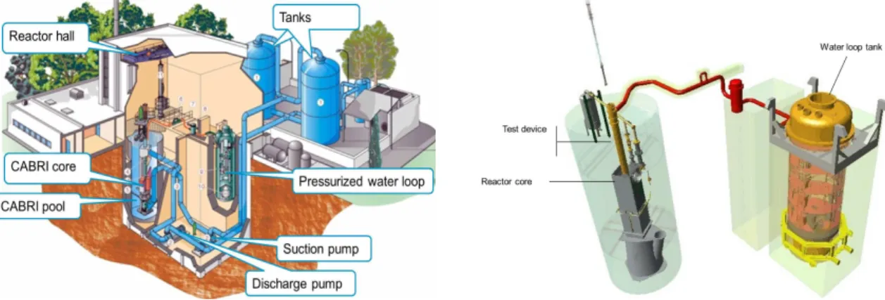
The CABRI facility (see Fig. 1) is made of the CABRI core and of 3 main systems (pressurized water loop, transient rods and primary cooling system) allowing to perform transient tests (RIA, LOCA) with a high level of representativeness, accuracy and safety. Those different components of the facility are described in the following sections.
Figure 1. Overall view of the CABRI facility (left) and of the pressurized water loop (right)
2.1. CABRI Core
CABRI is a pool-type reactor, with a core made of 1487 stainless steel clad fuel rods with 6% 235U enrichment. The reactor is able to reach a 23.7MW steady state power level. The reactivity is con-trolled via a system of 6 control and safety rods made of 23 hafnium pins for each (see Fig. 2).
2.2. Pressurized Water Loop
The new test loop allows reproducing the thermal hydraulics conditions of a pressurized water re-actor (300°C, 155bar, up to 6m3/h flowrate). It is composed (see Fig. 1 and Fig. 4) of an in-pile part connected to the experimental device and of an outside tank containing the main components (pres-surizer, pump, regulation valves…).
2.3. Transient Rods Circuit
The key feature of the CABRI reactor is its reactivity injection system [1]. This device (cf. Fig. 3) allows the very fast depressurization into a discharge tank of the 3He (strong neutron absorber) pre-viously introduced inside 96 tubes (so called “transient rods”) located among the fuel rods (see Fig. 2). The rapid absorber depressurization translates into an equivalent reactivity injection possi-bly reaching 4$ within a few 10ms. The power consequently bursts from 100kW up to ~20GW (cf. Fig. 4) in a few milliseconds and decreases just as fast due to the Doppler effect and other delayed reactivity feedbacks. The total energy deposit in the tested rod is adjusted by dropping the control and safety rods after the power transient.
Figure 3. Global view of the transient rods system (left) and of the typical CABRI 3He Pressure and core power shapes during a RIA transient (right)
2.4. Primary Cooling System
The primary cooling system [2] is illustrated in Fig. 1. A steady water flowrate (up to 3215m3/h) is needed to cool the fuel pins of the reactor driver core so as to respect the safety margins about the temperature of the claddings and of the oxide fuel during the power steady states and transients. The two tanks (250m3 each) feeding the cooling system are visible in the background. Water is sucked by two lines at the bottom of the tanks that join and merge into a single line of 600mm diameter. The suction and discharge pumps of the circuit are located at 11m below ground. Water thus passes initially by the suction pump, and then passes in the driver core of the reactor located in the pool and finally water is sent back to the top of the tanks through the discharge pump, which engages in order to regulate a stable level in the pool.
Transient rods Fast-opening
valves
Discharge tank
3. UPGRADE AND REFURBISHMENT OF THE CABRI FACILITY
Since 2003, the CABRI facility has been deeply upgraded and refurbished in order to be able to provide an improved experimental capacity with a pressurized water loop and to fit with ageing and safety issues. The description of the upgrades and of the refurbishment is given below.
3.1. Upgrade of the CABRI Facility
3.1.1. For experimental needs
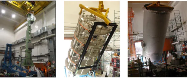
The new pressurized water loop (cf. Fig. 4) for CABRI has been manufactured and set up. Before the set up, it has been necessary to dismantle the previous sodium loop and to disassemble some internal structures of the pool.
Besides, a dedicated handling cask (cf. Fig. 4) was manufactured to be able to transfer or ship the test devices loaded with the irradiated test fuel pins inside and outside of the reactor building. Fi-nally, the radiography, imaging and spectrometry unit (IRIS) and the reactivity injection system have been upgraded and improved in terms of operability and of experimental capability and accu-racy.
Figure 4. Handling cask inside the reactor (left), support structures for the new CABRI water loop (center) and pressurized water loop vessel (right)
3.1.2. For regulatory needs
Heavy works were done on several systems and components of the CABRI facility in order to fit with the regulatory requirements. Most of them are related to the implementation of the new pres-surized water loop, to seismic reinforcements and to fire protection.
A non-exhaustive list of the main works is given below: - Replacement of the core vessel (see Fig. 2),
- Design and fabrication of high activity effluents circuits, - Upgrade of the overhead crane,
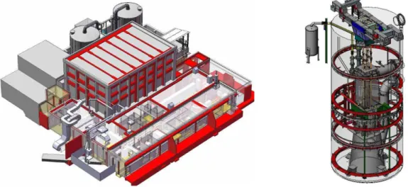
- Seismic reinforcements (cf. Fig. 5) of equipment (reactor vessel, circuits, tanks, doors, chimney…) and of the reactor and auxiliary buildings,
- Fire protection: division into fire areas, separation of the neutronic channels, revision of the ventilation,
- Creation of an ultimate emergency system, of an emergency shutdown panel, of an auxiliary building for storing sodium wastes, of a changing room and of a new public road network.
Figure 5. View (in red lines) of seismic reinforcements of the facility building (at left) and of the reactor vessel (at right)
3.2. Refurbishment of the CABRI Facility
The main refurbishment operations have been achieved. They mainly concerned the power and in-strumentation & control systems, the reactor building roof, the soil of the pump hall, the primary cooling system, the ventilation and the gasoil tank.
4. CABRI SAFETY REASSESSMENT
The authorizations for divergence and for realizing start-up transient tests (without test fuel pin in the center of the reactor) are delivered by the French regulator. We describe hereafter the main stag-es of the instruction of safety and the main safety studistag-es that were made at this date.
4.1. The Main Stages of the Instruction of Safety
Two permanent groups of experts were organized in 2004 and 2008 by the French regulator. They have issued opinions and recommendations that enable to take position on measures envisaged by the CEA for the restart of the CABRI reactor with a pressurized water loop.
In parallel, a huge work has been carried out to update and complete the organizational and safety documents. Concerning safety, the CABRI safety report has been updated to take into account all
the modifications of the facility and to address the new safety rules and recommendations emitted by the French regulators. The main rules of operation and the operation procedures were also up-dated. Reflex files were also created in case of crisis management.
In the continuity of the permanent groups, after realization of different safety studies (see section 4.2) and modification of the safety report of CABRI, the authorization of divergence of CABRI was obtained in September 2015. The final authorization for the CIP experimental tests is expected for 2017.
4.2. The Main Safety Studies
The update of the safety report needed numerous safety studies. Linked to the pressurized water loop implementation, studies were made about the pressure inside the loop due to the interaction between the fuel and the pressurized water in case of failure of the test fuel pin during RIA transi-ents, about decontamination of the loop after failure of the test fuel pin and about the behavior of heterogeneous connections between zircaloy and stainless steel tubes.
Neutronic studies (power peaks, reactivity effects, Doppler coefficient) [4] [5] were also performed, as well as studies on the thermomechanical behavior of the fuel pins of the CABRI core during RIA transients, on the siphon breaking system implemented on the primary cooling system, on the im-pact of sticking of the primary pumps, on criticality and on radiation and protection.
Reliability studies were also achieved dealing with the digital and analogic set of command of the transient rods and with the safety channel.
5. GENERAL ORGANIZATION AND STATUS OF THE RECOMMISSIONING
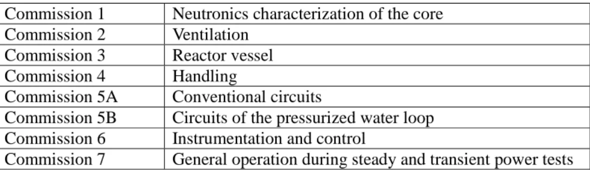
In the framework of the reactor restart, commissioning tests are realized for all equipment, systems and circuits of the reactor. Those tests are organized as presented in Table 1. Commission 1 tests [3] [6] started in October 2015. Commission 5B tests will be continued and finished in 2016, as well as commission 7 tests [6]. All the other commissioning tests have already been achieved.
Table 1. Organization of the CABRI commission tests
Commission 1 Neutronics characterization of the core Commission 2 Ventilation
Commission 3 Reactor vessel Commission 4 Handling
Commission 5A Conventional circuits
Commission 5B Circuits of the pressurized water loop Commission 6 Instrumentation and control
6. NEUTRONICS CHARACTERIZATION OF THE CORE
The neutronics commission tests aim at precisely characterizing the neutronics parameters of the CABRI core [3]: reactivity effects, power distributions and kinetic parameters. They will be carried out in 2015 and 2016, at low power (< 100kW), in natural convection and at ambient temperature. The different neutronics parameters and corresponding experimental techniques are given below.
6.1. Critical Position of the Control Rods
A standard method of subcritical approach is used to assess the critical position of the control rods for several realistic situations of operation depending on the below parameters. The critical position of the control rods in CABRI can depend on the following parameters: temperature of the moderator (water), pressure of 3He inside the transient rods, core stacking and content of the test cell.
6.2. Differential Reactivity Worth of the Control Rods
The first step of the measurement is to determine the excess of reactivity of supercritical situations using the classical asymptotic period method [7] [8] and the inhour equation of the CABRI reactor. The differential reactivity worth of the control rods (all control rods or single control rod) is then obtained by dividing the excess of reactivity of a supercritical situation by the difference of height of the control rods between their supercritical position and their critical position. As in section 6.1, this measurement is performed for several realistic situations of operation.
6.3. Integral Reactivity Worth of the Control Rods
The integral reactivity worth of the control rods will be assessed using two complementary tech-niques: the ASM/MSM technique [7] [9] and the rod drop technique [7] [8].
6.3.1. Worth curve of the control rods by the ASM/MSM technique
The amplified source method (ASM) is a type of subcritical measurement based on the point kinet-ics equations. It is based on the fact that the counting rate of fission chambers (R) is inversely pro-portional to the reactivity (ρ) of a steady-state subcritical level, see Equation (1):
R Seff
ε
ρ =− (1)
whereεis the detection efficiency of the chamber and Seff is the intrinsic source term.
In order to be able to accurately compare the reactivity worth of very different subcritical levels, a so-called MSM (Modified Source Modification) correction has to be considered for taking into ac-count the potential variation of detection efficiency and of intrinsic source between the states. Be-tween two states 0 and 1, the relation can be written as Equation (2):
4 4 3 4 4 2 1 correction MSM eff eff S S R R 0 , 0 1 , 1 0 1 0 1 ε ε ρ ρ =− × (2)
The MSM correction has to be calculated, for instance in the case of CABRI, using the French sto-chastic TRIPOLI4 code [10] in a subcritical mode. This method will also allow determining the « S » worth curve of the control rods (individually or all rods) from their fully inserted position to their critical position. This curve can be normalized to absolute reactivity worth either by using dif-ferential reactivity worth around the critical position or by using the integral reactivity worth meas-ured by rod drop technique.
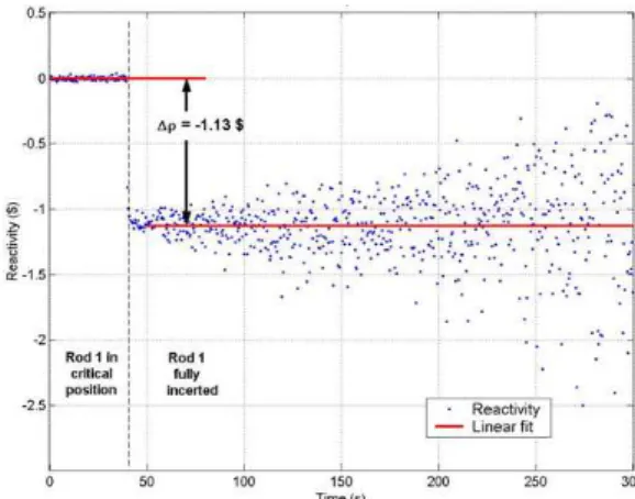
6.3.2. Integral worth by the rod drop technique
Rod drop experiments are based on kinetics equations in the point model. Practically, the counting of low power fission chambers is recorded during the drop (individual or all rods) of the control rods from their critical position. Two methods of treatment will be tested, for measuring the integral reactivity worth of control rods between their critical position and their fully inserted position:
• The method of linear or non-linear adjustment of flux [11], consisting in assessing simulta-neously the reactivity and the countings by adjustment of a transient model on the measured countings,
• The method of inversion of the point kinetics equations [11] in which the intrinsic source term and the mean reactivity of the final state (all rods inserted) is obtained by adjustment of the ρ(t) reactivity vs. time function (see Fig. 6).
Figure 6. Example of reactivity worth determination using the rod drop technique
The reactivity worth
ρ
obtained using the rod drop technique has to be corrected using the MSM correction defined in section 3.3.1. The estimation of the real reactivity worthρ
~ is obtained using Equation (3): − × − =β
ρ
β
ρ
1 1 ~ correction MSM (3)6.4. Isothermal Temperature Coefficient
The isothermal temperature coefficient is measured between two critical states of CABRI corre-sponding to two different temperatures of the moderator (pool water). Practically, a first critical state will be characterized for the ambient temperature of water (~20°C). Then water temperature will be increased of around 5 to 10°C after a heating phase during several hours of operation of the cooling system in forced convection (heating comes from the primary pumps operation).
The isothermal temperature coefficient is then deduced throughout Equation (4):
j i j j i i j i T T T T T − − = ∆ ∆ ( ) ( ) , ρ ρ ρ (4)
where Ti and Tj are the water temperatures corresponding to the two different critical states, and ∆ρ
is the variation of reactivity between the two states.
6.5. Reactivity Effects
The reactivity worth of core stacking, of the 3He transient rods (for different levels of pressuriza-tion) and of void effects in the water loop will be determined by difference of critical states, i.e. measuring the critical positions of the 6 control rods in the different operating situations.
6.6. Axial Distributions of Thermal and Epithermal Flux
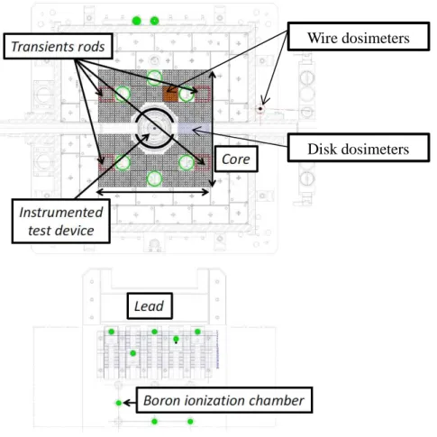
The axial distribution of thermal and epithermal flux will be measured using cobalt and gold dosim-eters (disks and wires) at different positions [6], inside the CABRI driver core and inside the central cell in which the test fuel pin is inserted (see Fig. 7 and Fig. 8).
After shipment to the MADERE platform [12] of CEA Cadarache, gamma-spectrometry measure-ments will be performed on all dosimeters.
Figure 7. Cobalt wire dosimeter (under quartz) and of cobalt and gold disk dosimeters (left); Inser-tion of the disk dosimeter aluminum holder inside the CABRI core upon the hodoscope device (center); Dummy assembly (also see Fig. 8) with 2 CFUL01 fission chambers and 4 dosimetry tubes
6.7. Kinetics Parameters
Kinetics parameters (β = effective fraction of delayed neutrons and Λ = prompt neutron generation time) are crucial parameters for the control of the reactor. They allow determining the Nordheim curve of a reactor. Cross power spectral density measurements [7] [11] [13] will be achieved during the neutronics commissioning tests. β and Λ will be inferred using equations (5) and (6):
2 $ 02 01 2 ) 1 ( 1 2 ρ β + = CPSD V V F D (5) and c f
π
β
2 = Λ (6)Where CPSD is the cross power spectral density between V01 and V02 (signals of the two fission
chambers positioned inside the dummy assembly), D is the Diven factor, ρ$ is the core reactivity in
dollars, fc is the break frequency of CPSD and F is the total number of fissions in the core per unit
of time. The determination of F will be performed using the measured activities of cobalt and gold wires placed at each corner of the dummy assembly (see Fig. 7) and knowing (by neutronics calcu-lations) their radiative capture rate per unit of flux.
6.8. Synthesis of the Measurement and of Target Uncertainties
Tab. 2 gives the synthesis of the measurement techniques that will be used during the neutronics commissioning tests, with the associated target uncertainties. A total of more than 200 measure-ments will be performed during about 4 months.
Table 2. Neutronics parameters, measurement techniques and target uncertainties for neutronics commissioning tests
7. CORE POWER AND ENERGY DEPOSIT DETERMINATION
The accurate measurement of the absolute power and hence of the total energy deposit during tran-sients is crucial. The power commissioning tests of CABRI will be performed in 2016.
The measurement of the core power is carried out using a heat balance method [14]. During steady states of power, this method consists in measuring the primary coolant heating for an accurate mon-itored flowrate. In the end the current delivered by experimental boron neutron detectors is cali-brated vs. the power measured by heat balance. However this calibration is only possible up to a 23.7MW power that is the maximum deliverable power level that can be obtained for a steady state operation of CABRI. An uncertainty around 4% (2σ) is expected.
Figure 4. Position of experimental boron neutron detectors (bottom, in green dots); Position of wire and disk dosimeters inside the CABRI core (control rods in green, dummy assembly in orange)
In order to check that this calibration is still reliable during power transient (up to 25GW), and hence that the linearity of experimental neutron detectors* (see Fig. 8) is good between 23.7MW and 25GW, we will compare the activities of 59Co and 197Au dosimeters generated during heat
* Note that 5 identical boron neutron detectors are positioned at 5 different distances from the core (see Fig. 4) in order
to be able to record the whole power profile during RIA transients, i.e. from 100kW to ~20GW
Wire dosimeters
ance measurements and during start up power transients (without test fuel pin in the center of the reactor).
This will be carried out during power commissioning tests, using a same position of wire dosimeters (outside of the graphite reflector surrounding the core (see Fig. 8) and targeting a same injected en-ergy in the driver core (270MJ) for both measurements [6]. In the end this will help to minimize the experimental uncertainty on absolute power measurements and to strengthen the estimation of the uncertainty on the energy deposit during power transients.
8. CONCLUSIONS
The upgrade and refurbishment of the CABRI facility have been successfully achieved. Those ac-tions, linked to the CABRI safety reassessment activities, led to the first divergence of CABRI in the pressurized water loop configuration in October 2015.
A global experimental program was built to process to neutronics and power commissioning tests of CABRI. It is based on an optimized (in terms of feasibility in the CABRI reactor and of target un-certainties) and complementary set of experimental techniques. A total of around 300 experiments will be performed during those tests in late 2015 and 2016 to demonstrate in the end the ability of CABRI to start the RIA CIP experimental program in 2017.
REFERENCES
[1] B. Duc, B. Biard, P. Debias, L. Pantera, JP. Hudelot, F. Rodiac, “Renovation, improvement and experimental validation of the Helium-3 transient rods system for the reactivity injection in the CABRI reactor,” IGORR2014 conference, 17-21 November 2014, Bariloche, Argentina
[2] JP. Hudelot, Y. Garnier, J. Lecerf, M. Fournier, S. Magnetto, E. Gohier, “CABRI reactor com-missioning: results and analysis of the tests on the primary cooling system and on the control and safety rods,” IGORR2014 conference, 17-21 November 2014, Bariloche, Argentina
[3] G. Ritter, O. Guéton, F. Mellier, and D. Beretz, “Neutron Commissioning in the New CABRI Water Loop Facility,” IEEE Transactions on Nuclear Science, Vol. 57, n°5, October 2010 [4] O. Guéton et al., “Neutronics computations in support of the CABRI core safety analysis,”
IGORR12 Conference, Beijin (China), October 28-30, 2009.
[5] J.P. Hudelot, A.C. Colombier, C. D’Aletto, J. Di Salvo, L. Gaubert, O. Guéton, O. Leray, P. Siréta, C. Vaglio-Gaudard, M. Valentini, “Development, validation and qualification of neu-tronics calculation tools for small reactors – application to the JHR, CABRI and OSIRIS reac-tors,” RRFM2012 Conference, Prague (Czech Republic), 18 - 22 March 2012
[6] JP. Hudelot, J. Lecerf, Y. Garnier, G. Ritter, O. Guéton, AC. Colombier, F. Rodiac, C. Domergue, “A complete dosimetry experimental program in support of the core characteriza-tion and of the power calibracharacteriza-tion of the CABRI reactor”, ANIMMA2015 Conference, Lisbon (Portugal), 2015
[7] G. Bignan, P. Fougeras, P. Blaise, JP. Hudelot, F. Mellier, “Handbook of Nuclear Engineering,” ISBN 978-0-387-98130-7 – Volume 3 - Reactor Physics Experiments on Zero Power Reactors – pp. 2053-2184
[8] JP. Hudelot, R.T. Klann, B. Micklich, M. Antony, G. Perret, N. Thiollay, JM. Girard, V. Laval, P. Leconte, “MINERVE Reactor Characterization in Support of the OSMOSE Program: Safety parameters”, PHYSOR 2004 conference, Chicago (US), 2004
[9] P. Blaise, F. Mellier P. Fougeras, “Application of the Modified Source Multiplication (MSM) Technique to Subcritical Reactivity Worth Measurements in Thermal and Fast Reactor Systems,” ANIMMA International Conference, 7-10 June 2009, Marseille, France
[10]E. Brun, E. Dumonteil, F. X. Hugot, N. Huot, C. Jouanne, Y. K. Lee, F. Malvagi, A. Mazzolo, O. Petit, J. C. Trama, and A. Zoia, “Overview of TRIPOLI-4 version 7 continuous-energy Monte Carlo transport code,” presented at the Int. Conf. ICAPP, Nice, France, May 2011
[11]G. Perret, “amélioration et développement des méthodes de détermination de la réactivité – Maîtrise des incertitudes associées“, PhD thesis, Orsay, 2003
[12]JM. Girard, H. Philibert, S. Testanière, Ch. Domergue and D. Beretz, “The MADERE Ra-dio-activity Measurement Platform: Developments for a Better Addressing to the Experimental Needs”, 978-1-4244-5208-8/09/ ©2009 IEEE
[13]I. Pazsit, C. Demazière, “Handbook of Nuclear Engineering,” ISBN 978-0-387-98130-7 – Volume 3 – Noise Techniques in Nuclear Systems – pp. 1629-1737
[14]F. Jeury, L. Pantera, Y. Garnier, “CABRI experimental reactor: experimental reassessment of CABRI core power and measurement uncertainties,” IGORR2013 conference, Daejeon (Korea), October 13-18, 2013