Publisher’s version / Version de l'éditeur:
Vous avez des questions? Nous pouvons vous aider. Pour communiquer directement avec un auteur, consultez la
première page de la revue dans laquelle son article a été publié afin de trouver ses coordonnées. Si vous n’arrivez pas à les repérer, communiquez avec nous à [email protected].
Questions? Contact the NRC Publications Archive team at
[email protected]. If you wish to email the authors directly, please see the first page of the publication for their contact information.
https://publications-cnrc.canada.ca/fra/droits
L’accès à ce site Web et l’utilisation de son contenu sont assujettis aux conditions présentées dans le site
LISEZ CES CONDITIONS ATTENTIVEMENT AVANT D’UTILISER CE SITE WEB.
Proceedings of the 5th International Conference Structures in Fire: 28 May 2008, Singapore, pp. 644-655, 2008-05-28
READ THESE TERMS AND CONDITIONS CAREFULLY BEFORE USING THIS WEBSITE.
https://nrc-publications.canada.ca/eng/copyright
NRC Publications Archive Record / Notice des Archives des publications du CNRC :
https://nrc-publications.canada.ca/eng/view/object/?id=90ddc348-81e9-4b91-8d7d-b12d487271cd https://publications-cnrc.canada.ca/fra/voir/objet/?id=90ddc348-81e9-4b91-8d7d-b12d487271cd
NRC Publications Archive
Archives des publications du CNRC
This publication could be one of several versions: author’s original, accepted manuscript or the publisher’s version. / La version de cette publication peut être l’une des suivantes : la version prépublication de l’auteur, la version acceptée du manuscrit ou la version de l’éditeur.
Access and use of this website and the material on it are subject to the Terms and Conditions set forth at
Fall-off of gypsum plasterboard in fire
http://irc.nrc-cnrc.gc.ca
F a l l - o f f o f g y p s u m p l a s t e r b o a r d i n f i r e
N R C C - 5 0 0 9 8
S u l t a n , M . A .
A version of this document is published in / Une version de ce document se trouve dans: Proceedings of the 5th International Conference Structures in Fire (SiF 2008),
Singapore, May 28-30, 2008, pp. 644-655
The material in this document is covered by the provisions of the Copyright Act, by Canadian laws, policies, regulations and international agreements. Such provisions serve to identify the information source and, in specific instances, to prohibit reproduction of materials without written permission. For more information visit http://laws.justice.gc.ca/en/showtdm/cs/C-42
Les renseignements dans ce document sont protégés par la Loi sur le droit d'auteur, par les lois, les politiques et les règlements du Canada et des accords internationaux. Ces dispositions permettent d'identifier la source de l'information et, dans certains cas, d'interdire la copie de documents sans permission écrite. Pour obtenir de plus amples renseignements : http://lois.justice.gc.ca/fr/showtdm/cs/C-42
FALL-OFF OF GYPSUM PLASTERBOARD IN FIRE
MOHAMED A. SULTAN1
ABSTRACT
This paper presents and discusses the results of an attempt that was made to determine the gypsum board fall-off temperature criterion from 80 full-scale fire resistance tests conducted at the National Research Council of Canada in accordance with ULC-S101/ASTM E119 standard fire exposure using floor assemblies constructed with wood joist, wood-I joist, steel C-joist and wood truss; protected with either one or two layers of Type X gypsum board and with and without insulation in the floor cavity. The proposed temperature criterion is based on the sudden temperature rise on the back side of the fire exposed gypsum board that is caused by either the board fall-off or board sagging. Statistical analysis of the gypsum board fall-off temperature is presented. A comparison of the fall-off time based on the temperature criterion and observed board fall-off from fire resistance tests is also presented.
1. INTRODUCTION
With the advent of performance-based codes and performance-based fire safety design options, the development of fire resistance models becomes an important tool to aid their implementation. Currently, major fire safety research efforts are being invested globally into developing numerical models that can be used by designers to facilitate the move to performance-based options. Development of such models faces several challenges such as the availability of reliable thermal and mechanical properties of materials, as well as information on the performance of building materials at elevated temperatures. In lightweight frame construction, one important limitation of the existing models is the prediction of gypsum board fall-off, which significantly impacts the prediction of fire resistance of an assembly. Studies1,2 showed that the gypsum board provides significant fire resistance protection, owing in major part to its high water content.
1
Dr. Sultan is a Senior Research Officer and Group Leader of the Fire Resistance and Risk Management
Subprogram, Fire Research Program, Institute for Research in Construction, National Research Council of Canada [email protected]
Fire resistance models typically consist of a thermal model and a structural model. The thermal model calculates the temperature history of the assembly’s components and feeds those temperatures to the structural model for determining the thermal and structural properties at a given time, which are used for calculating the response of the assembly. To calculate the temperature history, it is essential to determine how long the gypsum board ceiling will stay in place to protect the assembly’s frame. This can be defined either by the observed time of gypsum board fall-off or, alternatively, by the temperature at which the gypsum board will likely fall-off when exposed to heat. Due to the difficulty in predicting gypsum board fall-off times for assemblies with configurations that have not previously been tested, a time failure criterion is impractical for use in numerical modelling.
The National Research Council’s Institute for Research in Construction (NRC-IRC), in collaboration with industry and government partners, has carried out two major experimental research studies (Floors-I1 and Floors-II2) to measure the fire resistance and acoustic performance of full-scale floor assemblies with different framing types. Details on the assemblies’ construction and fire resistance results of these studies can be found in References 1 and 2. In these studies, gypsum board fall-off times were determined from test observations and video-recordings of the fire-exposed gypsum board surfaces in a floor furnace operating with premixed flame. Sultan, et al3, carried out a study on the gypsum board fall-off using 4 different approaches for characterizing the board fall-off when exposed to heat in standard fire tests. The first approach was based on the average temperature recorded at the time of fall-off, during fire resistance tests, of the first piece and at the time of fall-off of the last piece of each gypsum board layer. The second approach used the average of the first and last piece fall-off temperature criteria determined in the first approach. The gypsum board temperature at the time corresponding to the average of the first and last piece fall-off times was used to estimate the average fall-off temperature in the third approach. The last approach dealt with individual temperature histories and looked at the sudden increase in temperature caused by gypsum board fall-off. The purpose of this paper is to present in depth the last and recommended approach and to establish a temperature criterion for the gypsum board fall-off that can be used by the modelers to improve the accuracy of their fire resistance models for lightweight floor assemblies.
2. EXPERIMENTAL INVESTIGATION
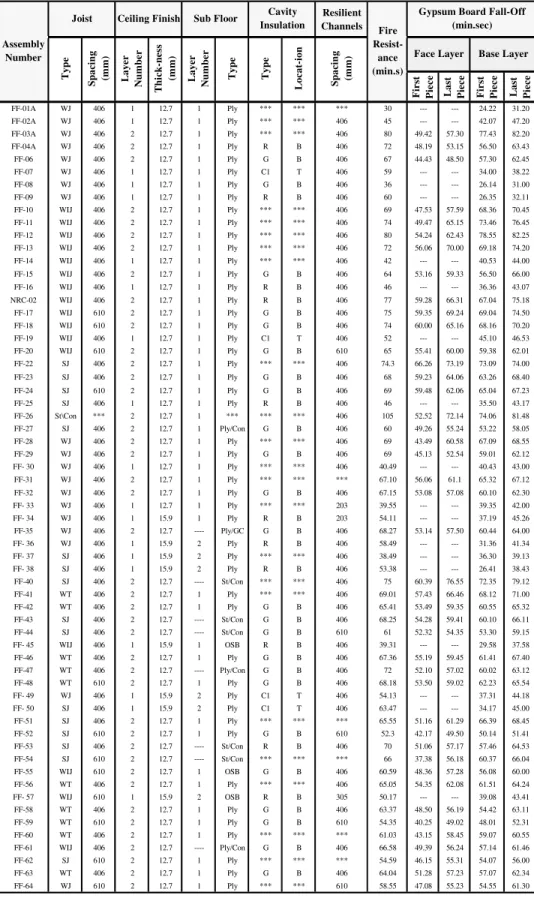
Eighty floor assemblies, 4.8 m long by 3.9 m wide, were constructed in accordance with CAN/CSA-A82.31-M914 to investigate the effect of different parameters on the fire resistance performance of floor assemblies consisting of solid wood, wood I- joists, steel C- joists and wood trusses. In 72 floor assemblies (see Table 1) resilient channels, spaced either 203 mm o.c. or 406 mm o.c., or 610 mm o.c., were used for sound reduction purposes and attached perpendicular to either the joists or trusses to support the gypsum board ceiling finish. Additional resilient channels were also installed to support gypsum board ends (board short dimension). The resilient channels, 14 mm deep by 58 mm wide, were fabricated from 0.6 mm thick galvanized steel sheets. The channels had a 34 mm wide web, designed to support the gypsum board connection, and one 18 mm wide flattened flange lip connected to the bottom of the joists or trusses. Three types of insulation were used: glass and rock fibre batts, and cellulose fibre insulation either sprayed wet on the underside of the sub-floor and on the side of the joists and allowed to dry to achieve an 11% moisture content or dry blown and supported at the bottom of the joists or trusses with a steel mesh.
Resilient Channels Fi rs t Piece La st Piece Fi rs t Piece La st Piece FF-01A WJ 406 1 12.7 1 Ply *** *** *** 30 --- --- 24.22 31.20 FF-02A WJ 406 1 12.7 1 Ply *** *** 406 45 --- --- 42.07 47.20 FF-03A WJ 406 2 12.7 1 Ply *** *** 406 80 49.42 57.30 77.43 82.20 FF-04A WJ 406 2 12.7 1 Ply R B 406 72 48.19 53.15 56.50 63.43 FF-06 WJ 406 2 12.7 1 Ply G B 406 67 44.43 48.50 57.30 62.45 FF-07 WJ 406 1 12.7 1 Ply C1 T 406 59 --- --- 34.00 38.22 FF-08 WJ 406 1 12.7 1 Ply G B 406 36 --- --- 26.14 31.00 FF-09 WJ 406 1 12.7 1 Ply R B 406 60 --- --- 26.35 32.11 FF-10 WIJ 406 2 12.7 1 Ply *** *** 406 69 47.53 57.59 68.36 70.45 FF-11 WIJ 406 2 12.7 1 Ply *** *** 406 74 49.47 65.15 73.46 76.45 FF-12 WIJ 406 2 12.7 1 Ply *** *** 406 80 54.24 62.43 78.55 82.25 FF-13 WIJ 406 2 12.7 1 Ply *** *** 406 72 56.06 70.00 69.18 74.20 FF-14 WIJ 406 1 12.7 1 Ply *** *** 406 42 --- --- 40.53 44.00 FF-15 WIJ 406 2 12.7 1 Ply G B 406 64 53.16 59.33 56.50 66.00 FF-16 WIJ 406 1 12.7 1 Ply R B 406 46 --- --- 36.36 43.07 NRC-02 WIJ 406 2 12.7 1 Ply R B 406 77 59.28 66.31 67.04 75.18 FF-17 WIJ 610 2 12.7 1 Ply G B 406 75 59.35 69.24 69.04 74.50 FF-18 WIJ 610 2 12.7 1 Ply G B 406 74 60.00 65.16 68.16 70.20 FF-19 WIJ 406 1 12.7 1 Ply C1 T 406 52 --- --- 45.10 46.53 FF-20 WIJ 610 2 12.7 1 Ply G B 610 65 55.41 60.00 59.38 62.01 FF-22 SJ 406 2 12.7 1 Ply *** *** 406 74.3 66.26 73.19 73.09 74.00 FF-23 SJ 406 2 12.7 1 Ply G B 406 68 59.23 64.06 63.26 68.40 FF-24 SJ 610 2 12.7 1 Ply G B 406 69 59.48 62.06 65.04 67.23 FF-25 SJ 406 1 12.7 1 Ply R B 406 46 --- --- 35.50 43.17 FF-26 St\Con *** 2 12.7 1 *** *** *** 406 105 52.52 72.14 74.06 81.48 FF-27 SJ 406 2 12.7 1 Ply/Con G B 406 60 49.26 55.24 53.22 58.05 FF-28 WJ 406 2 12.7 1 Ply *** *** 406 69 43.49 60.58 67.09 68.55 FF-29 WJ 406 2 12.7 1 Ply G B 406 69 45.13 52.54 59.01 62.12 FF- 30 WJ 406 1 12.7 1 Ply *** *** 406 40.49 --- --- 40.43 43.00 FF-31 WJ 406 2 12.7 1 Ply *** *** *** 67.10 56.06 61.1 65.32 67.12 FF-32 WJ 406 2 12.7 1 Ply G B 406 67.15 53.08 57.08 60.10 62.30 FF- 33 WJ 406 1 12.7 1 Ply *** *** 203 39.55 --- --- 39.35 42.00 FF- 34 WJ 406 1 15.9 1 Ply R B 203 54.11 --- --- 37.19 45.26 FF-35 WJ 406 2 12.7 ---- Ply/GC G B 406 68.27 53.14 57.50 60.44 64.00 FF- 36 WJ 406 1 15.9 2 Ply R B 406 58.49 --- --- 31.36 41.34 FF- 37 SJ 406 1 15.9 2 Ply *** *** 406 38.49 --- --- 36.30 39.13 FF- 38 SJ 406 1 15.9 2 Ply R B 406 53.38 --- --- 26.41 38.43 FF-40 SJ 406 2 12.7 ---- St/Con *** *** 406 75 60.39 76.55 72.35 79.12 FF-41 WT 406 2 12.7 1 Ply *** *** 406 69.01 57.43 66.46 68.12 71.00 FF-42 WT 406 2 12.7 1 Ply G B 406 65.41 53.49 59.35 60.55 65.32 FF-43 SJ 406 2 12.7 ---- St/Con G B 406 68.25 54.28 59.41 60.10 66.11 FF-44 SJ 406 2 12.7 ---- St/Con G B 610 61 52.32 54.35 53.30 59.15 FF- 45 WIJ 406 1 15.9 1 OSB R B 406 39.31 --- --- 29.58 37.58 FF-46 WT 406 2 12.7 1 Ply G B 406 67.36 55.19 59.45 61.41 67.40 FF-47 WT 406 2 12.7 ---- Ply/Con G B 406 72 52.10 57.02 60.02 63.12 FF-48 WT 610 2 12.7 1 Ply G B 406 68.18 53.50 59.02 62.23 65.54 FF- 49 WJ 406 1 15.9 2 Ply C1 T 406 54.13 --- --- 37.31 44.18 FF- 50 SJ 406 1 15.9 2 Ply C1 T 406 63.47 --- --- 34.17 45.00 FF-51 SJ 406 2 12.7 1 Ply *** *** *** 65.55 51.16 61.29 66.39 68.45 FF-52 SJ 610 2 12.7 1 Ply G B 610 52.3 42.17 49.50 50.14 51.41 FF-53 SJ 406 2 12.7 ---- St/Con R B 406 70 51.06 57.17 57.46 64.53 FF-54 SJ 610 2 12.7 ---- St/Con *** *** *** 66 37.38 56.18 60.37 66.04 FF-55 WIJ 610 2 12.7 1 OSB G B 406 60.59 48.36 57.28 56.08 60.00 FF-56 WT 406 2 12.7 1 Ply *** *** 406 65.05 54.35 62.08 61.51 64.24 FF- 57 WIJ 610 1 15.9 2 OSB R B 305 50.17 --- --- 39.08 43.41 FF-58 WT 406 2 12.7 1 Ply G B 406 63.37 48.50 56.19 54.42 63.11 FF-59 WT 610 2 12.7 1 Ply G B 610 54.35 40.25 49.02 48.01 52.31 FF-60 WT 406 2 12.7 1 Ply *** *** *** 61.03 43.15 58.45 59.07 60.55 FF-61 WIJ 406 2 12.7 ---- Ply/Con G B 406 66.58 49.39 56.24 57.14 61.46 FF-62 SJ 610 2 12.7 1 Ply *** *** *** 54.59 46.15 55.31 54.07 56.00 FF-63 WT 406 2 12.7 1 Ply G B 406 64.04 51.28 57.23 57.07 62.34 FF-64 WJ 610 2 12.7 1 Ply *** *** 610 58.55 47.08 55.23 54.55 61.30 Assembly Number
Joist Ceiling Finish
Type Spa c in g (mm) La y e r Nu m b e r Cavity Insulation Base Layer Fire Resist-ance (min.s)
Gypsum Board Fall-Off (min.sec) Face Layer Type L o c a t-io n Spa c in g (mm) Sub Floor La y e r Nu m b e r Thi c k-ne ss (mm) Type
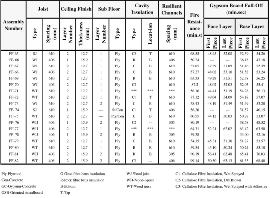
Resilient Channels Fi rs t P iece Last P iece Firs t P iece Last P iece FF-65 SJ 610 2 12.7 1 Ply C3 T 610 68.55 48.45 52.08 52.39 54.26 FF- 66 WJ 406 1 15.9 1 Ply R B 406 50.24 --- --- 36.18 43.18 FF-67 WJ 610 2 12.7 1 Ply G B 610 57.05 47.29 51.09 51.46 52.39 FF-68 WJ 406 2 12.7 1 Ply G B 610 57.27 48.02 53.10 51.58 53.24 FF-69 WJ 610 2 12.7 1 Ply R B 610 63.33 49.29 51.51 52.38 56.25 FF-70 WJ 406 2 12.7 1 Ply C2 --- 610 87.2 48.02 52.03 52.03 55.41 FF-71 WT 610 2 12.7 1 Ply *** *** *** 56.16 44.41 51.19 54.28 56.13 FF-72 WT 610 2 12.7 1 Ply C1 T 610 77.12 49.04 54.09 54.18 57.07 FF-73 WJ 610 2 12.7 2 Ply G B 610 58.43 48.19 51.49 51.49 53.20 FF- 74 SJ 610 1 15.9 ---- St/Con C1 T 406 56.20 --- --- 31.57 40.15 FF-75 WT 610 2 12.7 ---- Ply/Con G B 610 60.55 44.12 50.03 50.28 53.07 FF- 76 WIJ 406 1 15.9 2 Ply C2 --- 305 80.19 --- --- 38.58 48.32 FF-77 WIJ 406 2 12.7 1 Ply *** *** *** 64.31 52.21 62.02 63.42 63.50 FF- 78 WIJ 406 1 15.9 2 Ply R B 305 59.38 --- --- 33.00 42.16 FF-79 WT 610 2 12.7 1 Ply G B 610 54.35 45.31 51.30 51.27 53.57 FF-80 WT 610 2 12.7 1 Ply R B 610 59.34 45.10 50.24 50.24 53.10 FF-81 WIJ 406 2 15.9 2 Ply R B 305 90.19 56.41 62.48 65.41 76.03 FF-82 WT 406 2 15.9 2 Ply C2 --- 406 99.14 50.50 63.13 61.33 68.40 Ply-Plywood G-Glass fibre batts insulation WJ-Wood joist
Con-Concrete R-Rock fibre batts insulation WIJ-Wood-I-joist
GC-Gypsum-Concrete B-Bottom WT-Wood truss C3- Cellulose Fibre Insulation, Wet Sprayed with Adhesive OSB-Oriented strandboard T-Top
C1- Cellulose Fibre Insulation, Wet Sprayed C2- Cellulose Fibre Insulation, Dry Blown
Assembly Number
Joist Ceiling Finish Sub Floor
Ty p e Ty p e Spaci ng (m m) La ye r Nu m b e r T hi c k-nes s (m m) Face Layer
Gypsum Board Fall-Off (min.sec) La ye r Nu m b e r Cavity Insulation Base Layer Fire Resist-ance (min.s) Ty p e Lo c a t-io n Spaci ng (m m)
Table 1: Design Details and Gypsum Board Fall-Off Time (continue)
The glass, rock and cellulose insulation satisfied CSA A101-M835, CAN/ULC S702-M976 and CGSB 51.60-M907, respectively. The sub-floor types used in the assemblies were either Canadian Softwood Plywood (CSP) or steel deck with concrete topping. The ceiling finish used in the assemblies was Type X gypsum board, 12.7 mm and 15.9 mm thick, and had Firecode C designation and met the requirements of Type X gypsum board8,9. The gypsum boards had an average surface density of 9.85 kg/m2 for a nominal 12.7 mm thick board and 10.5 kg/m2 for a nominal 15.9 mm thick board. They were attached perpendicular either to resilient channels in 72 assemblies or directly to the framing in 8 assemblies. Table 1 summarizes the main variable parameters of the assemblies studied. Complete construction details can be found in References 1 and 2.
2.1 Instrumentation and Test Conditions
In addition to the standard instrumentation specified in CAN/ULC-S101-M8910, numerous thermocouples (over 100) were placed within each floor assembly in order to obtain temperature histories at various locations during fire tests for further use beyond the scope of the above-mentioned studies. Type K (20 gauge) chromel-alumel thermocouples, with a thickness of 0.91 mm, were used for measuring the temperatures of the sub-floor surface and gypsum board surface facing the floor cavity as well as the interface surface between the gypsum board for assemblies with two layers of gypsum board and between the gypsum board and insulation at the floor cavity side. Temperature readings were recorded every minute across the floor assemblies. Details on the locations of the thermocouples can be found in References 1 and 2. All floor assemblies were tested with a superimposed load depending on the components of the assembly. Assemblies FF-01A to FF-09 were tested using a restricted load of 75% of maximum
design load; while assemblies FF-10 to FF-82 were tested on a maximum design load. Two video cameras were used to record the fire-exposed gypsum board performance.
The assembly’s gypsum board ceiling finish was exposed to heat in a propane-fired horizontal furnace in accordance with CAN/ULC-S101-M8910, “Standard Methods of Fire Endurance Tests of Building Construction and Materials”. The furnace temperature was measured by nine (20 gauge) shielded thermocouples and the average of these thermocouples was used to control the furnace temperature in such a way that it followed, as closely as possible, the CAN/ULC-S101-M89 standard temperature-time curve. Subsequently, the time of fall-off of the first and last pieces of each gypsum board layer for all assemblies was determined from test observations and through viewing of the video recordings of the experiments.
3. RESULTS AND DISCUSSION
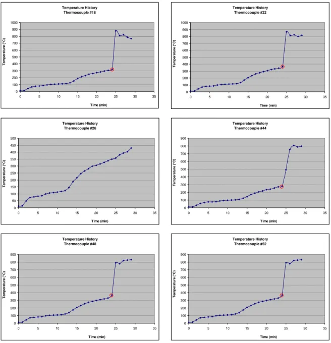
The results of the 80 full-scale fire resistance floor tests, including the time of fall-off of gypsum board layers, are summarised in Table 1 above. The temperature rise on the back face of gypsum board layers (six for each layer) was recorded for all experiments. As an example for the reader, a set of these temperature histories, from floor assembly FF-01A, is provided in Figure 1. An important characteristic identified in these temperature history graphs was a sudden and significant increase in temperature over a period of a few minutes only (often an increase of more than 300°C over a period of a minute). The sudden temperature rises observed seem to correspond to the increase in temperature caused by the fall-off of the gypsum board layer at the location of the thermocouple; the fallen board piece allowing heat to penetrate rapidly into the next layer of the assembly. Some graphs did not display this expected sudden increase in temperature. A variety of factors can explain this phenomenon. An important one to consider is a malfunction of the thermocouple studied. Another factor could be that only cracking or a partial gypsum board fall-off occurred at the location of the thermocouple, which would cause the temperature to increase over a longer period of time. Finally, it is possible that the gypsum board did not fall-off at that thermocouple location.
It is interesting to note that, for assembly FF-01A, no sudden increase in temperature is seen for thermocouple #26, which recorded a maximum temperature of 430°C before the recording instrument was turned off due to the termination of the test. All other thermocouples registered temperatures over 800°C after the 24th
minute. This observation suggests that gypsum board remained in place at the location of thermocouple #26, protecting the latter from a rapid temperature increase until data recording was ended.
The temperature at which gypsum board falls off for each thermocouple was thus established as the last temperature recorded before the sudden temperature rise in the layer. Circles were drawn around the selected values in Figure 1 for more clarity. In cases where the step in temperature was not as clearly defined as the ones seen in Figure 1, the average of the two recordings bracketing the base of this sudden temperature rise was taken as the fall-off temperature. Temperature histories with no such sudden temperature increase or multiple temperature steps of the same magnitude were ignored when fall-off temperatures were calculated. The fall-off temperature of each gypsum board layer was then computed as the average of the fall-off temperatures found for each layer. Certain subjectivity was used at this stage to ignore data points that seemed erroneous, most probably due to a dysfunction of the thermocouple.
Figure 1 Temperature Histories at the Unexposed Face of the Gypsum Board Layer (Assembly FF-01A) Temperature History Thermocouple #18 0 100 200 300 400 500 600 700 800 900 1000 0 5 10 15 20 25 30 35 Time (min) Te m pe ra tur e ( °C ) Temperature History Thermocouple #22 0 100 200 300 400 500 600 700 800 900 1000 0 5 10 15 20 25 30 35 Time (min) Te m p e rat ur e ( °C ) Temperature History Thermocouple #26 0 50 100 150 200 250 300 350 400 450 500 0 5 10 15 20 25 30 35 Time (min) T emp er at u re ( °C ) Temperature History Thermocouple #44 0 100 200 300 400 500 600 700 800 900 0 5 10 15 20 25 30 35 Time (min) T emp er at u re ( °C ) Temperature History Thermocouple #48 0 100 200 300 400 500 600 700 800 900 0 5 10 15 20 25 30 35 Time (min) Te m p e rat ur e ( °C ) Temperature History Thermocouple #52 0 100 200 300 400 500 600 700 800 900 0 5 10 15 20 25 30 35 Time (min) Te m p e rat ur e ( °C )
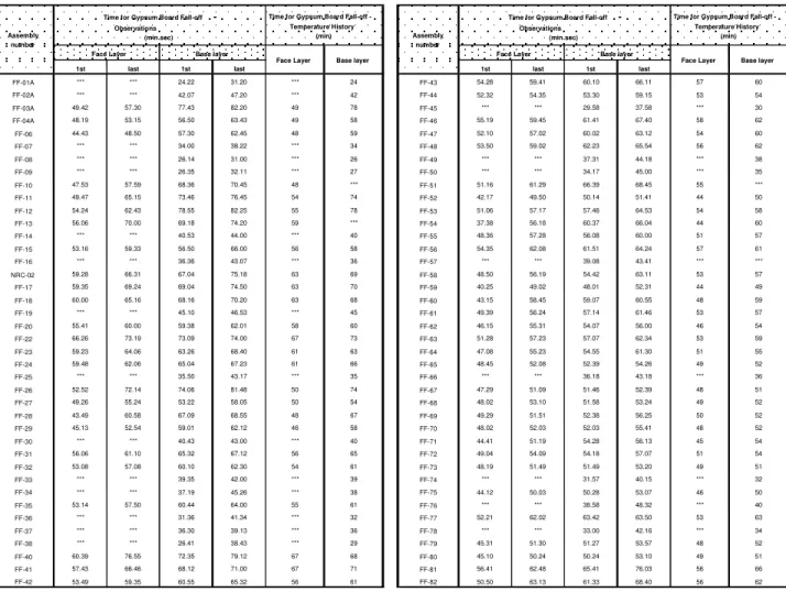
To ensure that this method gave results that were consistent with observations made during the experiments, the time corresponding to the temperature of fall-off selected was recorded for each thermocouple. Those times were then compared to the fall-off times reported in Table 2. It was seen that temperature increases often occurred up to a minute before the first piece of fall-off was reported. This could be due to cracking in the gypsum board leading to gypsum board fall-off within a short period of time. The time range for fall-off was thus extended by a minute before the first piece of fall-off. Temperatures from the thermocouples with fall-off times outside the expanded time range were discarded. Only 21 points out of 822 temperatures were disregarded due to this reason, which corresponds to 2.6% of the readings. The mean values of fall-off times corresponding to the temperatures selected with this approach are reported in Table 2 for comparison with the fall-off times observed during fire tests. The fall-off temperatures were determined using the procedure described above to ensure that the
temperature increase caused by the fall-off of a piece would not be accounted for in the determination of the temperature causing the piece to fall off.
Figures 2 through 4 show the statistical analysis of the fall-off temperatures found for single layer assemblies without insulation, with glass or rock fibre insulation at the bottom of the cavity and with cellulose fibre insulation and at the top of the cavity and framing sides using resilient channels (RC) spaced at 406 mm o.c., respectively. An important temperature difference is seen between non-insulated and insulated assemblies. This could be due to the added thermal resistance caused by the insulation installation in the floor cavity. The highest temperature is found for assemblies with insulation at the bottom of the cavity above the gypsum board and the lowest is for non-insulated assemblies.
Figures 5 to 14 show the statistical analysis of temperatures found with this method for double gypsum board layer assemblies. Figures 5 through 8 (assemblies with no insulation in the floor cavity) and 9 through 12 (assemblies with insulation in the floor cavity) show the impact of resilient channels spacing (i.e. lower the spacing the more screws) on both face and base layer. Once again, gypsum board fall-off temperatures are highest in assemblies insulated at the bottom of the cavity and lowest in non-insulated assemblies. The base layer fall-off temperatures are found to be significantly lower than face layer fall-off temperatures. Reasons that could explain this phenomenon will be proposed in a later section. As in previous cases, fall-off temperatures are lower with assemblies using wider resilient channels pacing (less number of screws). This difference seems to be more significant for base layer temperatures. This method shows the largest difference in temperature from one category to another or between base and face layers. On the other hand, all standard deviations reported for double layer assemblies, excluding Figures 5 and 6, are below 50°C.
This approach accounts for the fact that the gypsum board layers fall in separate pieces at unevenly distributed intervals to determine the temperature of fall-off. By considering each thermocouple separately, this ensures that the temperature selected represents gypsum board fall-off as closely as the temperatures recorded allow it. The temperature obtained is thus really the temperature at the time of gypsum board fall-off, not the temperature of the gypsum board at the location of the thermocouple at the time of fall-off of a piece of gypsum of a different location.
The only principal drawback of this method of determining temperature criteria for gypsum board is its subjectivity and limited number of thermocouples. Indeed, the location of the sudden temperature rise on the temperature history graphs was not always clearly defined and a fair amount of subjectivity was necessary to select the appropriate temperature. Also, when determining the fall-off temperature of each assembly, data points that did not follow the trend established by other points were sometimes ignored.
The temperature histories studied for this analysis not only present what seems to be the most realistic estimate of the Type X gypsum board fall-off temperatures, but also provides precious information that is key for understanding the behaviour of the different components comprised in floor assemblies.
Interesting observations were derived from the results of the previous analyses. Firstly, the presence and the location of the insulation within the floor assembly were identified as the major factors influencing the temperature of fall-off of gypsum board layers.
It was observed that fall-off temperatures were lowest for non-insulated assemblies, and highest when the insulation was applied directly against the gypsum board layers. This suggests
Temperature Criteria For Sudden Temperature Rise At Single Layer Fall-Off 0 100 200 300 400 500 600 FF-01A FF-02A FF-14 FF-30 FF-37 Assembly number T em p er at u re ( °C ) Average: 439 Standard deviation: 58
Temperature Criteria For Sudden Temperature Rise At Single Layer Fall-Off
0 100 200 300 400 500 600 700 800 900 FF-08 FF-09 FF-16 FF-25 FF-36 FF-38 FF-45 FF-66 Assembly number T em p er at u re ( °C ) Average: 680 Standard deviation: 53
Figure 2 Assembly with single layer of Gypsum Board Figure 3 Assembly with single layer of Gypsum Board and and no Insulation in Floor Cavity Glass or Rock Fibre Insulation in Floor Cavity
1st last 1st last FF-43 54.28 59.41 60.10 66.11 57 60 FF-44 52.32 54.35 53.30 59.15 53 54 FF-45 *** *** 29.58 37.58 *** 30 FF-46 55.19 59.45 61.41 67.40 58 62 FF-47 52.10 57.02 60.02 63.12 54 60 FF-48 53.50 59.02 62.23 65.54 56 62 FF-49 *** *** 37.31 44.18 *** 38 FF-50 *** *** 34.17 45.00 *** 35 FF-51 51.16 61.29 66.39 68.45 55 *** FF-52 42.17 49.50 50.14 51.41 44 50 FF-53 51.06 57.17 57.46 64.53 54 58 FF-54 37.38 56.18 60.37 66.04 44 60 FF-55 48.36 57.28 56.08 60.00 51 57 FF-56 54.35 62.08 61.51 64.24 57 61 FF-57 *** *** 39.08 43.41 *** *** FF-58 48.50 56.19 54.42 63.11 53 57 FF-59 40.25 49.02 48.01 52.31 44 49 FF-60 43.15 58.45 59.07 60.55 48 59 FF-61 49.39 56.24 57.14 61.46 53 57 FF-62 46.15 55.31 54.07 56.00 46 54 FF-63 51.28 57.23 57.07 62.34 53 59 FF-64 47.08 55.23 54.55 61.30 51 55 FF-65 48.45 52.08 52.39 54.26 49 52 FF-66 *** *** 36.18 43.18 *** 36 FF-67 47.29 51.09 51.46 52.39 48 51 FF-68 48.02 53.10 51.58 53.24 49 52 FF-69 49.29 51.51 52.38 56.25 50 52 FF-70 48.02 52.03 52.03 55.41 48 52 FF-71 44.41 51.19 54.28 56.13 45 54 FF-72 49.04 54.09 54.18 57.07 51 54 FF-73 48.19 51.49 51.49 53.20 49 51 FF-74 *** *** 31.57 40.15 *** 32 FF-75 44.12 50.03 50.28 53.07 46 50 FF-76 *** *** 38.58 48.32 *** 40 FF-77 52.21 62.02 63.42 63.50 53 63 FF-78 *** *** 33.00 42.16 *** 34 FF-79 45.31 51.30 51.27 53.57 48 52 FF-80 45.10 50.24 50.24 53.10 49 51 FF-81 56.41 62.48 65.41 76.03 56 66 FF-82 50.50 63.13 61.33 68.40 56 62 Assembly number
Time for Gypsum Board Fall-off - Observations
(min.sec)
Time for Gypsum Board Fall-off - Temperature History
(min) Face Layer Base layer
Face Layer Base layer 1st last 1st last FF-01A *** *** 24.22 31.20 *** 24 FF-02A *** *** 42.07 47.20 *** 42 FF-03A 49.42 57.30 77.43 82.20 49 78 FF-04A 48.19 53.15 56.50 63.43 49 58 FF-06 44.43 48.50 57.30 62.45 48 59 FF-07 *** *** 34.00 38.22 *** 34 FF-08 *** *** 26.14 31.00 *** 26 FF-09 *** *** 26.35 32.11 *** 27 FF-10 47.53 57.59 68.36 70.45 48 *** FF-11 49.47 65.15 73.46 76.45 54 74 FF-12 54.24 62.43 78.55 82.25 55 78 FF-13 56.06 70.00 69.18 74.20 59 *** FF-14 *** *** 40.53 44.00 *** 40 FF-15 53.16 59.33 56.50 66.00 56 58 FF-16 *** *** 36.36 43.07 *** 36 NRC-02 59.28 66.31 67.04 75.18 63 69 FF-17 59.35 69.24 69.04 74.50 63 70 FF-18 60.00 65.16 68.16 70.20 63 68 FF-19 *** *** 45.10 46.53 *** 45 FF-20 55.41 60.00 59.38 62.01 58 60 FF-22 66.26 73.19 73.09 74.00 67 73 FF-23 59.23 64.06 63.26 68.40 61 63 FF-24 59.48 62.06 65.04 67.23 61 66 FF-25 *** *** 35.50 43.17 *** 35 FF-26 52.52 72.14 74.06 81.48 50 74 FF-27 49.26 55.24 53.22 58.05 50 54 FF-28 43.49 60.58 67.09 68.55 48 67 FF-29 45.13 52.54 59.01 62.12 46 58 FF-30 *** *** 40.43 43.00 *** 40 FF-31 56.06 61.10 65.32 67.12 56 65 FF-32 53.08 57.08 60.10 62.30 54 61 FF-33 *** *** 39.35 42.00 *** 39 FF-34 *** *** 37.19 45.26 *** 38 FF-35 53.14 57.50 60.44 64.00 55 61 FF-36 *** *** 31.36 41.34 *** 32 FF-37 *** *** 36.30 39.13 *** 36 FF-38 *** *** 26.41 38.43 *** 29 FF-40 60.39 76.55 72.35 79.12 67 68 FF-41 57.43 66.46 68.12 71.00 67 71 FF-42 53.49 59.35 60.55 65.32 56 61 Base layer Assembly number
Time for Gypsum Board Fall-off - Observations
(min.sec) Face Layer Base layer
Time for Gypsum Board Fall-off - Temperature History
(min) Face Layer
Table 2 Comparison of Observed Fall-Off and Time of Sudden Temperature Rise
that gypsum fall-off temperature depends on the rate at which heat accumulates in the board. Severity of fire exposure using time and temperature relationships could potentially provide more generic fall-off criteria for numerical modelling. This would require calculating the cumulative board temperature between the beginning of the fire test and the time of fall-off of the assembly.
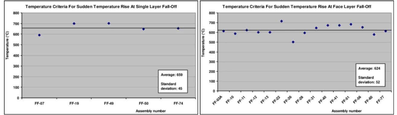
Temperature Criteria For Sudden Temperature Rise At Single Layer Fall-Off 0 100 200 300 400 500 600 700 800 FF-07 FF-19 FF-49 FF-50 FF-74 Assembly number T em p er at u re ( °C ) Average: 659 Standard deviation: 45
T emperature Criteria For Sudden Temperature Rise At Face Layer Fall-Off
0 100 200 300 400 500 600 700 800 FF-0 3A FF-10 FF-11 FF-1 2 FF-13 FF-22 FF-26 FF-28 FF-31 FF-4 0 FF-41 FF-5 1 FF-56 FF-60 FF-7 7 Assembly number T em p er at u re ( °C ) Average: 624 Standard deviation: 52
Figure 4 Assembly with single layer of Gypsum Board Figure 5 Assembly with Two layers (Face Layer) of Gypsum And Cellulose Spray-on Fibre Insulation Board and no Insulation and RC at 406 mm o.c.
Temperature Criteria For Sudden Temperature Rise At Base Layer Fall-Off
0 100 200 300 400 500 600 700 FF-0 3A FF-10 FF-11 FF-1 2 FF-13 FF-22 FF-26 FF-28 FF-31 FF-4 0 FF-41 FF-5 1 FF-56 FF-60 FF-7 7 Assembly number T em p er at u re ( °C ) Average: 428 Standard deviation: 88
Temperature Criteria For Sudden Temperature Rise At Face Layer Fall-Off
0 100 200 300 400 500 600 FF-54 FF-62 FF-64 FF-71 Assembly number T em p er at u re ( °C ) Average: 514 Standard deviation: 48
Figure 6 Assembly with Two layers (Base Layer) of Figure 7 Assembly with Two layers (Face Layer) of Gypsum Gypsum Board, Cellulose and RC at 406 mm o.c. Board, no Insulation and RC at 610 mm o.c.
Temperature Criteria For Sudden Temperature Rise At Base Layer Fall-Off
0 50 100 150 200 250 300 350 400 FF-54 FF-62 FF-64 FF-71 Assembly number T em p er at u re ( °C ) Average: 332 Standard deviation: 42
T emperature Criteria For Sudden Temperature Rise At Face Layer Fall-Off
0 100 200 300 400 500 600 700 800 FF-04A FF-0 6 FF-1 5 NRC -02 FF-1 7 FF-1 8 FF-2 3 FF-2 4 FF-27FF-2 9 FF-3 2 FF-3 5 FF-4 2 FF-4 3 FF-4 6 FF-4 7 FF-4 8 FF-5 3 FF-5 5 FF-5 8 FF-6 1 FF-6 3 Assembly number T em p e rat u re ( °C ) Average: 684 Standard deviation: 38
Figure 8 Assembly with Two layers (Base Layer) of Figure 9 Assembly with Two layers (Face Layer) of Gypsum Gypsum Board, no Insulation and RC at 610 mm o.c. Board, Glass or Rock Insulation and RC at 406 mm o.c.
Resilient channels spacing dictates the number of screws and spacing used in the attachment of the gypsum board, and thus the loading on each screw. Screw spacing, i.e. loading per screw on a gypsum board sheet, appears to influence the temperature of fall-off of gypsum board. The temperature of fall-off was noted to be lower for assemblies with wider screw spacing. The larger loading per screw on assemblies with wider screw spacing causes larger stresses in the board at the screw locations. This could reduce the capacity of the board to sustain additional stress and cracking could also be induced more quickly at points under high stress in the board. These factors combined would explain why gypsum board falls off at a lower temperature for assemblies using wider resilient channels spacing. It was also seen that, in the
case of double layer gypsum board assemblies, the fall-off temperature of the face layer of gypsum board tends to be higher than the fall-off temperature of single gypsum board layer assemblies, while the base layer fall-off temperatures are usually significantly lower than face layer fall-off temperatures. Face layer temperatures are expected to be higher in double layer gypsum board assemblies than in single layer assemblies, since the second gypsum layer acts as an additional insulation layer. The low temperatures associated with the fall-off of gypsum board base layer, on the other hand, are most likely caused by thermal shock as the result of sudden fall-off of the face gypsum board layer which could lead to cracking and eventually fall off of the base layer faster.
Temperature Criteria For Sudden Temperature Rise At Base Layer Fall-Off
0 100 200 300 400 500 600 700 800 FF-04 A FF-0 6 FF-1 5 NRC -02 FF-1 7 FF-1 8 FF-2 3 FF-2 4 FF-27FF-2 9 FF-3 2 FF-3 5 FF-4 2 FF-4 3 FF-4 6 FF-4 7 FF-4 8 FF-5 3 FF-5 5 FF-5 8 FF-6 1 FF-6 3 Assembly number T em p e rat u re ( °C ) Average: 623 Standard deviation: 44
T emperature Criteria For Sudden Temperature Rise At Face Layer Fall-Off
0 100 200 300 400 500 600 700 800 FF-6 7 FF-6 8 FF-6 9 FF-7 3 FF-7 5 FF-7 9 FF-8 0 FF-5 9 FF-52 FF-4 4 FF-2 0 Assembly number T em p er at u re ( °C ) Average: 636 Standard deviation: 44
Figure 10 Assembly with Two layers (Base) of Gypsum Figure 11 Assembly with Two layers (Face Layer) of Gypsum Board, Glass or Rock Insulation and RC at 406 mm o.c. Board, Glass or Rock Insulation and RC at 610 mm o.c.
Temperature Criteria For Sudden Temperature Rise At Base Layer Fall-Off
0 100 200 300 400 500 600 FF-2 0 FF-4 4 FF-5 2 FF-5 9 FF-6 7 FF-6 8 FF-6 9 FF-7 3 FF-75 FF-7 9 FF-8 0 Assembly number T em p er at u re ( °C ) Average: 478 Standard deviation: 42
T emperature Criteria For Sudden Temperature Rise At Face Layer Fall-Off
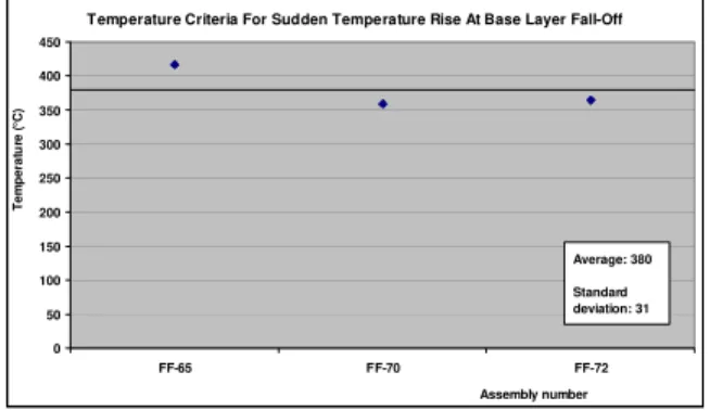
0 100 200 300 400 500 600 700 FF-65 FF-70 FF-72 Assembly number T em p e rat u re ( °C ) Average: 604 Standard deviation: 42
Figure 12 Assembly with Two layers (Base) of Gypsum Figure 13 Assembly with Two layers (Face Layer) of Gypsum Board Board, Glass or Rock Insulation and RC at 610 mm o.c. Board and Cellulose Insulation and RC at 610 mm o.c.
Temperature Criteria For Sudden Temperature Rise At Base Layer Fall-Off
0 50 100 150 200 250 300 350 400 450 FF-65 FF-70 FF-72 Assembly number T em p e rat u re ( °C ) Average: 380 Standard deviation: 31
Figure 14 Assembly with Two layers (Base Layer) of Gypsum Board, Cellulose Insulation and RC at 610 mm o.c.
4. TEMPERATURE CRITERIA
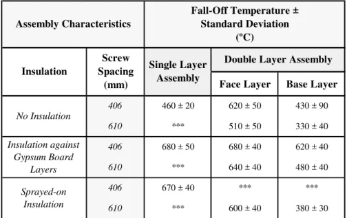
The sudden rise in temperature criteria is based on the fact that the fall-off temperatures are determined in a manner that ensures the temperature increase caused by the fall-off of a gypsum piece is not accounted for in the determination of the temperature causing gypsum board to fall off. Table 3 shows the gypsum board fall-off temperature criteria. The values found in this table are taken at the back face of each gypsum board and are based on assemblies constructed with resilient channels. The installation of resilient channels in double layer floor assemblies did not impact the fall-off temperature of gypsum board face layers, which do not come directly in contact with them. In contrast, the recorded fall-off temperatures for base layers, as well as gypsum boards in single layer assemblies, were significantly reduced (by approximately 100°C) in assemblies built without resilient channels. The temperatures found in Table 3 are intended for use with, 12.7 mm thick, Type X gypsum boards. On average, the temperatures were found to be higher for thicker gypsum boards, but it was not possible to establish a clear relationship between board thickness and fall-off temperature due to the limited number of assemblies built with 15.9 mm thick Type X gypsum boards. No single gypsum board layer assembly with 610 mm screw spacing was tested. Only one double layer assembly with sprayed-on insulation and screw spacing at 406 mm was tested and experimental results were not sufficiently consistent for a judgment to be made on the fall-off temperature to use.
Face Layer Base Layer
Insulation against Gypsum Board Layers Sprayed-on Insulation 406 610 406 610 406 610 Insulation Assembly Characteristics Fall-Off Temperature ± Standard Deviation (ºC) No Insulation
Double Layer Assembly Single Layer Assembly Screw Spacing (mm) 460 ± 20 *** 620 ± 50 680 ± 50 *** 670 ± 40 *** 430 ± 90 330 ± 40 620 ± 40 510 ± 50 680 ± 40 640 ± 40 *** 600 ± 40 480 ± 40 *** 380 ± 30
Table 3 Type X Gypsum Board Fall-off Temperature Criteria
5. SUMMARY
In this paper, an attempt was made to establish temperature failure criteria for gypsum board. Key findings are as follows:
1. The installation of insulation within the floor assembly was identified as the major factors influencing the temperature of fall-off of gypsum board layers.
2. Fall-off temperatures were lowest for non-insulated assemblies, and highest when the insulation was applied directly against the gypsum board layers.
3. The temperature of fall-off was lower for assemblies with wider resilient channels spacing (less number of screws).
4. A second layer of gypsum board increased the fall-off time for the gypsum board layer exposed to the fire (face layer) compared to an assembly with only one layer of gypsum board, even though the base layer fell off relatively quickly compared to the face layer due to a thermal shock caused by board exposure to heat once the face layer had dropped off.
6. REFERENCES
1. Sultan, M.A., Séguin,Y.P., Leroux, “Results of Fire Resistance Tests on Full-Scale Floor Assemblies”, Internal Report No. 764, Institute for Research in Construction, National Research Council of Canada, Ottawa, ON, 1998.
2. Sultan, M.A, Latour, J.C., Leroux, P., Monette, R.C., Séguin, Y.P. and Henrie, J. “Results of Fire Resistance Tests on Full-scale Floor Assemblies – Phase II”, Research Report 184, Institute for Research in Construction, National Research Council Canada, Ottawa, Ontario, 2005.
3. Sultan, M.A. and Roy-Poirier “Gypsum board fall-off temperature in floor assemblies exposed to standard fires," Interflam 2007, Proceedings of the 11th International Conference on Fire Science and Engineering (London, UK, September 03, 2007), pp. 979-991, September 03, 2007
4. " CAN/CSA-A82.31-M91, Gypsum Board Application, Canadian Standards Association, Rexdale, ON, 1991.
5. CSA A101-M83, Thermal Insulation, Canadian Standards Association, Rexdale, Ontario, 1983.
6. CAN/ULC-S702-M97, Standard for Mineral Fibre Thermal Insulation for Buildings, Underwriters’ Laboratories of Canada, Scarborough, Ontario, 1997.
7. CAN/CGSB 51.60-M90, Cellulose Fibre Loose Fill Thermal Insulation, Canadian Standards Board, Ottawa, Ontario, 1990.
8. CAN/CSA-82.27-M91, Gypsum Board, Canadian Standards Association, Etobicoke, Ontario, Canada, 1991.
9. ASTM C36-97, Standard Specification for Gypsum Wallboard, American Society for Testing and Materials, West Conshohocken, PA, June 1997.
10. CAN/ULC-S101-M89, Standard Methods of Fire Endurance Tests of Building Construction and Materials. Underwriters' Laboratories of Canada, Scarborough, ON, 1989.