Publisher’s version / Version de l'éditeur:
MATERIALS PROCESSING AND DESIGN; Modeling, Simulation and
Applications; NUMIFORM '07; Proceedings of the 9th International Conference on
Numerical Methods in Industrial Forming Processes, pp. 793-798, 2007-05-17
READ THESE TERMS AND CONDITIONS CAREFULLY BEFORE USING THIS WEBSITE. https://nrc-publications.canada.ca/eng/copyright
Vous avez des questions? Nous pouvons vous aider. Pour communiquer directement avec un auteur, consultez la
première page de la revue dans laquelle son article a été publié afin de trouver ses coordonnées. Si vous n’arrivez pas à les repérer, communiquez avec nous à PublicationsArchive-ArchivesPublications@nrc-cnrc.gc.ca.
Questions? Contact the NRC Publications Archive team at
PublicationsArchive-ArchivesPublications@nrc-cnrc.gc.ca. If you wish to email the authors directly, please see the first page of the publication for their contact information.
NRC Publications Archive
Archives des publications du CNRC
This publication could be one of several versions: author’s original, accepted manuscript or the publisher’s version. / La version de cette publication peut être l’une des suivantes : la version prépublication de l’auteur, la version acceptée du manuscrit ou la version de l’éditeur.
For the publisher’s version, please access the DOI link below./ Pour consulter la version de l’éditeur, utilisez le lien DOI ci-dessous.
https://doi.org/10.1063/1.2740907
Access and use of this website and the material on it are subject to the Terms and Conditions set forth at
Crashworthiness of aluminium tubes; Part 2: improvement of
hydroforming operation to increase absorption energy
D'Amours, Guillaume; Rahem, Ahmed; Mayer, Robert; Williams, Bruce;
Worswick, Michael
https://publications-cnrc.canada.ca/fra/droits
L’accès à ce site Web et l’utilisation de son contenu sont assujettis aux conditions présentées dans le site LISEZ CES CONDITIONS ATTENTIVEMENT AVANT D’UTILISER CE SITE WEB.
NRC Publications Record / Notice d'Archives des publications de CNRC:
https://nrc-publications.canada.ca/eng/view/object/?id=a17b66e7-31b8-4be3-becd-822011debbea https://publications-cnrc.canada.ca/fra/voir/objet/?id=a17b66e7-31b8-4be3-becd-822011debbeaCrashworthiness of Aluminium Tubes; Part 2: Improvement
of Hydroforming Operation to Increase Absorption Energy
Guillaume D'Amours
*, Ahmed Rahem
*, Robert Mayer
**, Bruce Williams
***and
Michael Worswick
****
National Research Council Canada, Aluminium Technology Centre, 501 University Blvd. East, Chicoutimi, Quebec, Canada, G7H 8C3
**
General Motors Technical Centre, 6250 Chicago Road, Warren, MI, USA
***
University of Waterloo, 200 University Avenue West, Waterloo, Ontario, Canada, N2L 3G1
Abstract
. The motivation to reduce overall vehicle weight within the automotive sector drives the substitution of lightweight materials such as aluminium alloys for structural components. Such a substitution requires a significant amount of development to manufacture structurally parts such that the energy absorption characteristics are not sacrificed in the event of crash. The effects of the manufacturing processes on the crash performance of automotive structural components must be better understood to ensure improved crashworthiness. This paper presents results of an experimental and numerical investigation of the crash response and energy absorption properties of impacted hydroformed aluminium alloy tubes. Crash experiments on hydroformed tubes were performed using a deceleration sled test at the General Motors Technical Center. Results from axial crush testing showed that an important parameter that influences the energy absorption characteristics during crash was the thickness reduction caused by circumferential expansion of the tube during hydroforming. It was found that that the energy absorption decreased as the corner radius decreased, which results because of increased thinning. Sensitivity studies of end feeding parameters, such as end feed level and profile, were carried out to evaluate their impact on the energy absorption of the aluminium tubes.Keywords: crashworthiness, absorption energy, crush force, hydroforming, aluminium, end feed, finite element simulation, wall thickness reduction
INTRODUCTION
The use of aluminium is actually increasing for the manufacture of automotive frame structures in order to reduce their weight and their fuel consumption. Moreover, the forming methods are also developing in order to reduce the number of manufacturing steps and their associated costs. According to Asnafi et al. [1], the weight of the body structure can be reduced by up to 50 % by using aluminium and new forming and joining techniques. Some automotive manufacturers are now using the hydroforming process to manufacture specific structural frame components such as the side members. According to Mortimer [2], the growing use of hydroformed parts is attributed to increased strength and rigidity, weight and parts reduction and improvement of crashworthiness. In a larger project involving General Motors, the University of Waterloo, Queens University and the Aluminium Technology Centre, the crashworthiness of
hydroformed straight and S-rail aluminium tubes is studied.
The determination of the absorption energy of hydroformed tubes during a crash event can be obtained by both experimental tests and finite element simulations. De Kanter [3] analyzed the crashworthiness of straight tubes experimentally and by using analytical and numerical methods. The numerical results agreed well with experimental ones but the analytical formulas gave limited accuracy. Grantab et al. [4], Oliveira et al. [5] and Zheng et al. [6] have used successfully the finite element method to evaluate the crashworthiness of bent tubes. To obtain accurate finite element solutions for crash events, crash models should account for the forming history of hydroformed tubes. Kirby et al. [7] observed an increase of about 9 % of the absorption energy of a hydroformed part during a crash simulation when the forming results were mapped.
793
CP908, NUMIFORM ‘07, Materials Processing and Design: Modeling, Simulation and Applications edited by J. M. A. César de Sá and A. D. Santos
D'Amours et al. [8] compared predicted results of tube wall thickness reductions to measured ones. They showed that finite element simulation results are generally comparable to those measured when using solid elements for the hydroforming simulations. As observed by D'Amours et al. [8], the tube wall thinning at the half length of the hydroformed tubes is firstly a function of the maximum end feed level applied during the hydroforming operation. However, the profile of the end feed load curve can also affect the tube wall thinning. As these tubes will be used as automotive frame components, it is indispensable to know the effect of these variations of tube wall thickness reductions on their absorption energy.
Williams et al. [9] evaluated the absorption energy of hydroformed tubes without end feed. In the case of a low pressure hydroforming process, a decrease of the absorption energy was observed with sharper corner fillet radii for tubes formed. This paper will allow observing the variations of absorption energies of tubes hydroformed with different insert sets for high pressure hydroforming and end feed loading. In order to improve the absorption energy of hydroformed tubes, sensibility studies will be realized to identify the end feed load curves that maximize absorption energy. Similar numerical sensitivity studies of bending process parameters on crashworthiness of bent tubes were done by Oliveira et al. [5].
VALIDATION OF NUMERICAL
MODELS
Measure of Crush Forces
Crash tests have been performed by General Motors on aluminium tubes previously hydroformed at the Aluminium Technology Centre. A horizontal sled was used to simultaneously crash two identical tubes during each test. To easily initiate a first fold of the tube wall at the beginning of the crash, crash beads (fold initiators) were incorporated on two opposing flat sides of the tube. Tube ends were cut to length and clamps attached to the ends. Figure 1 shows tubes and fixtures used to clamp the tubes for horizontal sled impact.
Load cells measured the crush force transmitted to each of the two tubes during each test. From measured crush distance, it was possible to continuously evaluate the absorption energy. The mean crush force is finally computed during the crash event as the ratio of the absorption energy with the crush distance. Results of some measured mean crush forces from differently hydroformed tubes are shown in figure 2. As anticipated, the mean crush force is widely
influenced by the hydroforming process. In figure 2, at the same crush distance of 200 mm and for the same end feed level of 44 mm, the tube hydroformed up to corner fillet radii of 12 mm absorbed more energy relative to the one that were hydroformed up to radii of 6 mm. For the same 6 mm corner-fill radii, the tube hydroformed with the high end feed of 64 mm is the one that absorbed the highest energy relative to the one hydroformed with a final end feed of 44 mm.
FIGURE 1. Clamping fixtures for hydroformed tubes
FIGURE 2. Measured crush forces of some differently
hydroformed tubes
Successive Finite Element Simulations
To obtain realistic absorption energies during simulations of the crash events, it is important to incorporate the results from the hydroforming simulations into the crash models. The method that is generally used with the commercial finite element code LS-DYNA is related to a file called ``dynain'' which possesses the tube mesh and the finite element solutions at each integration point. Between the simulation of the hydroforming operation and the crash event, other simulations such as the springback of the tube during the opening of the die, the creation
of the crash beads and finally the tube trimming was performed. Each one of the successive simulations include the deformed mesh and the finite element results of the previous ones with the corresponding ``dynain'' file.
Shell elements of size 4x4 mm were used in the hydroforming simulations in order to save computational time. A conventional piecewise linear plasticity material model was used to reproduce the behavior of the aluminium AA5754. The explicit solver of LS-DYNA was used to perform the simulation of the hydroforming operation. The simulation of the tube springback was then realized with the implicit solver of LS-DYNA. For the creation of crash beads on two opposite surfaces of the hydroformed tube, a specific finite element model was developed for the tools used to create the beads. Figure 3 shows the hydroformed tube after the creation of the two beads of 5 mm depth. Also shown in figure 3, both circular ends of the tube were trimmed to reduce the number of elements for the crash simulation.
FIGURE 3. Crash beads created
After performing the finite element simulations for a specific insert set and end feed level and preserving the finite element solutions in the dynain files, the crash simulation is executed. A rigid wall moving in the axial direction of the tube, crush its free end. The nodes of the other tube end are constraints in translation and rotation during the crash. To calculate the accumulated energy of the horizontal sled prior the crash event, the parameters defined in table 1 are used for the rigid wall.
TABLE 1.Parameters used for the rigid wall. Mass
(gram)
Initial velocity (mm/msec)
560.0E+3 7.0
During the crash simulation, the contact force between the rigid wall and the free tube end is automatically computed by LS-DYNA. The evolution of the mean crush force as function of the crush distance is the computed from these data. The experimental crash tests corresponding to the three different hydroforming cases and for which the results are shown in figure 2, were simulated numerically. The predicted results are shown in figure 4.
FIGURE 4. Predicted mean crush forces
The predicted curves were generally similar to the experimental ones except for the first peak loads which are all under-predicted. These variations can be attributed to the presence and the behavior of the beads used during the crash. Predicted mean crush forces at a crush distance of 200 mm are compared to the experimental ones by varying both the corner fillet radii and the end feed levels. Results are shown in figures 5 and 6.
FIGURE 5. Mean crush forces for different radii
Both figures show that the predicted values under-predict lightly the experimental ones. However, they follow almost the same increasing tendency with
respect to the corner fillet radius and end feed level. These results confirm that the finite element method is an adequate tool to predict the crashworthiness of differently hydroformed tubes.
FIGURE 6. Mean crush forces for different end feed levels
CRASHWORTHINESS
IMPROVEMENT
Influence of Corner Fillet Radii and End
Feed Level
The previous section confirmed that the corner-fill radii, and the maximum end feed level used during hydroforming operation, can increase the crashworthiness of the aluminium tubes during a crash event. It was important to determine which combination of corner fillet radii and end feed level lead to the highest crush force and improved the crashworthiness of the aluminium tubes. Sensitivity studies will be performed and one parameter will be varied at a time and all the successive finite element calculations will be performed in order to evaluate the corresponding mean crush force.
For the first sensitivity analysis, the 6 mm insert set was used for the hydroforming simulation and the maximum level of the end feed loading was varied from 4.1 mm (end feed used during the sealing operation of the tube) to 94.1 mm, by increments of 10 mm. For each different maximum end feed level, the shape of the normalized end feed load curve was preserved but scaled by the maximum level. Successive simulations from the hydroforming up to the crash are performed for each different end feed load curve. Figure 7 shows the predicted mean crush forces at 200 mm crush distance.
FIGURE 7. Predicted mean crush forces for the insert set of 6 mm and different end feed levels
Results show that there is always an increase of the absorption energy of the aluminium tube when the maximum end feed level increased during the hydroforming operation. From the first load case with the maximum end feed of 4.1 and the last one of 94.1 mm, the mean crush force is passed from 39 to 67 kN, which corresponds to an increase of 72 % for the 6 mm insert set. This increase of absorption energy can be attributable to the increase of tube wall thickness due to the increasing maximum end feed level used during the hydroforming operation.
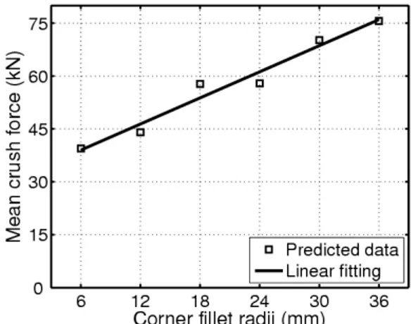
A second sensitivity analysis was performed by varying the corner-fill radii of the aluminium tubes during the hydroforming operation while maintaining the same end feed level. Six different corner-fill radii from 6 mm to 36 mm by increment of 6 mm were analyzed and the maximum end feed level was fixed to 4.1 mm. Results are shown in figure 8.
FIGURE 8. Predicted mean crush forces for different insert sets and the minimum end feed
The absorption energy of the aluminium tubes decreases when the corner-fill radius of the hydroformed tubes becomes smaller. From the insert set with 36 mm radius to the 6 mm one, there is a reduction of 48 % of the mean crush force for the hydroformed tubes.
Influence of the End Feed Load Curve Shape
Raising Time Variation
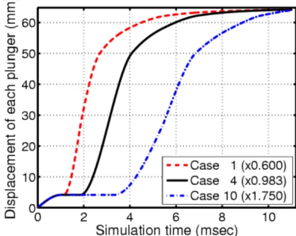
Previous analysis showed that the final amplitude of the end feed load curve used during the hydroforming operation has an influence on the absorption energy of the tubes. The shape of the end feed load curve used for the hydroforming operation will be now investigated. For the present analysis, the raising time of the end feed following the sealing operation of the tube will be reduced and then increased by the use of ten different end feed curves. This raising time represents the moment corresponding to the beginning of the end feed during the hydroforming operation. Ten different raising times will be defined for the analysis and the original end feed load curve with the maximum level of 64 mm will be modified to create the new ones.
Figure 9 shows three different curves with different raising times. The original end feed load curve has a raising time of about 0.189 msec. The case 4 of the new end feed curves is the one which is the most similar to the original one. In figure 9, case 1 and case 10 represent the raising times that are the most distant from the case 4.
FIGURE 9. New end feed load curves with different
raising times
One hydroforming simulation was performed for each of the ten different end feed load curves. The 6 mm insert set was used for the simulations.
Springback, creation of crash beads, trimming and crash of the resulting tube have been successively performed for each case. The resulting mean crush forces are shown in figure 10. The variation of the mean crush force corresponding to the ten different cases is about 3 %, which is negligible. Thus, mean crush force of the differently hydroformed tubes was almost insensitive to different raising times used to define the end feed load curves.
FIGURE 10. Predicted mean crush forces Variation of the End Feed Load Curve Slope
Always hoping to increase the absorption energy of the hydroformed tubes, the shape of the end feed load curve was once again investigated. The raising time of the curve is now fixed at 0.189 msec and the slope of the curve following this time is modified. Ten different slopes were used for this sensitivity analysis and the one (case 3) that is the most similar to the original end feed curve is shown in figure 11. The two extreme cases with lower and higher slopes are also shown in figure 11.
FIGURE 11. End feed load curves with different
slopes
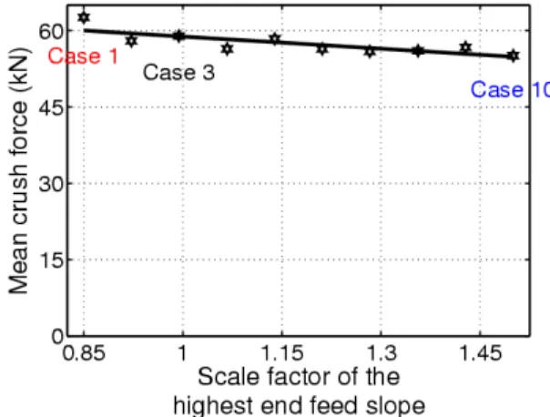
Tubes are once again hydroformed up to corner-fill radius of 6 mm for the ten different end feed load curves. All the successive finite element simulations leading the crash event for each hydroformed tube have been performed. The computed mean crush forces obtained for the ten different slope cases are shown in figure 12.
FIGURE 12. Predicted mean crush forces
Results show that there is a small decrease of the mean crush force when the scale factor of the slope of the end feed curve increases. The linear fitting allows predicting a reduction of 9 % of the mean crush force between the case 1 and the case 10. This process parameter plays a more important role on the absorption energy of the aluminium tubes than the raising time of the end feed load curve. Nevertheless, the observed variation of the mean crush force is not enough to consider this parameter an important factor when hydroforming aluminium tubes.
CONCLUSION
Aluminium straight tubes were hydroformed at the Aluminium Technology Centre with different insert sets and end feed levels. The hydroformed tubes have been thereafter crash tested at General Motors Technical Center in order to evaluate their absorption energy. As expected, the different tube shapes with different wall thickness reductions led to different amounts absorption energy. Finite element models were developed to simulate these crash events. The solutions obtained from the finite element simulations allowed to obtain mean crush forces similar to the experimental ones.
With the developed and validated finite element models, it was possible to analyze the influence of some process parameters related to the hydroforming operation on the absorption energy of aluminium tubes. Sensibility studies of the corner-fill radii, the
maximum end feed level and the shape of the end feed load curve were performed. The parameter that has the highest influence on the absorption energy is the corner-fill radius of the hydroformed tubes. However, when the corner-fill radius of the hydroformed has to be kept small, it is possible to increase considerably the absorption energy of the tubes by increasing the maximum end feed level applied during the hydroforming operation.
ACKNOWLEDGMENTS
General Motors of Canada, the Natural Sciences and Engineering Research Council of Canada and the National Research Council of Canada are gratefully acknowledged for supporting this work. The authors would like to express their gratitude to General Motors, the Aluminium Technology Centre and the University of Waterloo for their involvement in this project.
REFERENCES
1. N. Asnafi, T. Nilsson, and G. Lassl, Materials
Science and Engineering (2003).
2. J. Mortimer, Assembly automation 21, 317–321 (2001).
3. J. de Kanter, Energy absorption of monolithic and
fibre reinforced aluminium cylinders, Ph.D. thesis,
Delft University of Technology (2006).
4. R. Grantab, D. Oliveira, B. Williams, M. Worswick, and R. Mayer, International journal of
crashworthiness 11, 165–175 (2006).
5. D. Oliveira, M. Worswick, R.Grantab, B. Williams, and R. Mayer, International journal of impact
engineering 32, 826–846 (2006).
6. L. Zheng, and T. Wierzbicki, International journal
of crashworthiness 9, 155–173 (2004).
7. D. Kirby, S. Roy, and R. Kunju, “Optimization of tube hydroforming with consideration of manufacturing effects on structural performance,” in Numisheet 2005, edited by L. Smith, F. Pourboghrat, J. Yoon, and T. Stoughton, 2005, pp. 585–590.
8. G. D’Amours, A. Rahem, B. Williams, M. Worswick, and R. Mayer, “Crashworthiness of aluminium tubes; Part 1 :hydroforming at different corner-fill radii and end feeding levels,” in
Numiform 2007, edited by josé César de Sá, 2007.
9. B. Williams, D. Oliveira, M. Worswick, and R. Mayer, SAE International (2004).
10. P. Du Bois, C. Chou, B. Fileta, T. Khalil, A. King, H. Mahmood, H. Mertz, and J. Wismans, Vehicle