Publisher’s version / Version de l'éditeur:
Vous avez des questions? Nous pouvons vous aider. Pour communiquer directement avec un auteur, consultez la première page de la revue dans laquelle son article a été publié afin de trouver ses coordonnées. Si vous n’arrivez pas à les repérer, communiquez avec nous à [email protected].
Questions? Contact the NRC Publications Archive team at
[email protected]. If you wish to email the authors directly, please see the first page of the publication for their contact information.
https://publications-cnrc.canada.ca/fra/droits
L’accès à ce site Web et l’utilisation de son contenu sont assujettis aux conditions présentées dans le site LISEZ CES CONDITIONS ATTENTIVEMENT AVANT D’UTILISER CE SITE WEB.
Technical Proceedings of the 2007 NSTI Nanotechnology Conference and Trade
Show, 1, pp. 320-323, 2007-05-24
READ THESE TERMS AND CONDITIONS CAREFULLY BEFORE USING THIS WEBSITE. https://nrc-publications.canada.ca/eng/copyright
NRC Publications Archive Record / Notice des Archives des publications du CNRC : https://nrc-publications.canada.ca/eng/view/object/?id=f520d05b-8ab4-49fe-a7a9-1c41ed8e1c00 https://publications-cnrc.canada.ca/fra/voir/objet/?id=f520d05b-8ab4-49fe-a7a9-1c41ed8e1c00
NRC Publications Archive
Archives des publications du CNRC
This publication could be one of several versions: author’s original, accepted manuscript or the publisher’s version. / La version de cette publication peut être l’une des suivantes : la version prépublication de l’auteur, la version acceptée du manuscrit ou la version de l’éditeur.
Access and use of this website and the material on it are subject to the Terms and Conditions set forth at
Optical and structural characterization of nanostructured Alq
₃ with
negative in-plane birefringence
Szeto, Bryan; Hrudey, Peter C. P.; Gospodyn, James; Sit, Jeremy C.; Brett,
Michael J.
Optical and structural characterization of nanostructured Alq
3with negative
in-plane birefringence
Bryan Szeto, Peter C. P. Hrudey, James Gospodyn, Jeremy C. Sit, and Michael J. Brett
Dept. of Electrical and Computer Engineering, University of Alberta
2
ndFloor ECERF, University of Alberta, Edmonton, Alberta, Canada, T6G 2V4
[email protected]
ABSTRACT
In this study, we investigate the optical and structural properties of tilted columnar thin films composed of Alq3 in
order to better understand the nature of the in-plane birefringence exhibited by such films. Alq3 films have
demonstrated a notable absence of column broadening and secondary structural anisotropy that are commonly observed in inorganic films and also exhibit larger column tilt angles. These structural properties gave rise to optical anisotropy leading to negative values of in-plane birefringence of the films that increase with deposition angle, whereas in inorganic thin films the peak values of positive in-plane birefringence occur at deposition angles 60° < α < 70°. Variable angle spectroscopic ellipsometry, scanning electron microscopy, and the Bruggeman effective medium approximation description were used to characterize the films.
Keywords: glancing angle deposition, nanostructured
materials, birefringence, Alq3, ellipsometry
1
INTRODUCTION
The optical properties of organic tris (8-hydroxyquinoline) aluminum (Alq3) chiral thin films
deposited at glancing angles have been a focus of interest recently due to the precise chiral (helical) architectures that may be fabricated [1, 2]. These studies have demonstrated a notable absence of column broadening and secondary structural anisotropy (asymmetric fanning of columns) commonly observed in inorganic films. In addition, strong chiral optical behaviour is observed in Alq3 helical films,
with a dependence on the deposition angle. Previous studies have shown that the magnitude of circular Bragg reflection (preferential reflection of one handedness of circular polarized light) of chiral thin films is related to the in-plane birefringence [3]. This suggests that the in-plane birefringence of tilted columnar Alq3 films drives the chiral
optical behaviour and that the birefringence should increase with the deposition angle. Such a trend is contrary to the one observed in tilted columnar inorganic thin films which tend to exhibit peak values of in-plane birefringence at deposition angles 60° < α < 70° [4].
In this study, we investigate the optical and structural properties of tilted columnar thin films composed of Alq3 in
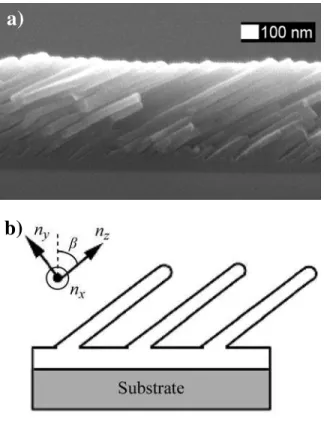
order to better understand the source of the in-plane birefringence for films deposited using the glancing angle deposition (GLAD) technique [5]. An example of a tilted columnar film deposited at 71° is shown in Fig. 1(a). Our investigations include the use of variable angle spectroscopic ellipsometry (VASE), scanning electron microscopy (SEM), and the Bruggeman effective medium approximation (BEMA) description to determine the principal indices of refraction of tilted columnar Alq3 films
(Fig. 1(b)), as well as structural parameters such as the column tilt angle, β, and the relative film density which are used to calculate the plane birefringence, ∆n. The in-plane birefringence is defined as:
p
x
n
n
n
=
−
∆
(1) The index of refraction in the deposition plane parallel to the substrate, np, is given by:2 1 2 y 2 2 z 2 p n β cos n β sin n − ⎟ ⎟ ⎠ ⎞ ⎜ ⎜ ⎝ ⎛ + = (2)
where nx is the index in the substrate plane perpendicular to
the deposition plane, ny is in the deposition plane and
perpendicular to the column posts, and nz is aligned in the
direction of the posts.
Knowledge of the optical parameters of Alq3 is critical
to designing and modeling of proposed nanostructured devices incorporating chiral or porous architectures such as square-spiral photonic crystals, rugate filters, and polarized light emitting devices [1, 6, 7].
2
FILM DEPOSITION
Alq3 powder purchased from Gelest Inc. (>99% purity)
was baked at 150°C for several hours under rough vacuum to remove water vapor and potential solvents. Alq3 thin
films were deposited by thermal evaporation onto silicon (100) wafers at base pressures of < 8 x 10⁻⁵ Pa. The deposition rate during the evaporations was monitored using a quartz crystal microbalance (QCM). Slanted columnar thin films were fabricated at various incident angles 65° ≤ α ≤ 87°.
Figure 1: (a) Cross-sectional SEM image of a slanted columnar Alq3 thin film deposited at α = 71° and (b) an
illustration of the corresponding principal indices of refraction.
3
OPTICAL CHARACTERIZATION
A commercial variable angle spectroscopic ellipsometer (V-VASE, J. A. Woollam Co., Inc.) was used to optically characterize the films. Optical modelling was performed using the software package supplied with the ellipsometer (WVASE32 version 3.517, J. A. Woollam Co., Inc.). The normalized Mueller matrices [8] of the films were measured over the wavelength range of 400 to 1300 nm using the V-VASE in reflection mode at light angles of incidence from 40° to 60° with respect to substrate normal.
The obliquely deposited Alq3 films were modeled
using three layers on top of a silicon substrate. The first layer represented the solid layer of Alq3 that forms prior to
the growth of individual structures [1, 9]. The second layer used the BEMA to describe the biaxial slanted posts, where the two constituent media consisted of Alq3 and void (i.e.
nvoid = 1, kvoid = 0). Since the effective medium mixture was
anisotropic, we used a BEMA that can account for the for cylindrically shaped inclusions [10], as was done in a similar study [11, 12]. The third layer consisted of a surface roughness layer in order to compensate for slight variations in column heights between individual posts. The modelling parameters consisting of the three layer thicknesses, the film density in the tilted column layer, the screening parameters describing the cylindrical inclusions, and the Euler angles θ (which in our case is synonymous
with β) and φ which describe the column orientation with respect to the lab coordinate system were simultaneously fit using the modeling software. The Euler angle, φ, is the azimuthal angle that describes the orientation of the columns in the substrate plane. All of our fit results in the software were given an error bar corresponding to the 90% confidence limit, which was used to compute any error bars that appear in figures presented throughout this work.
a)
4
RESULTS
4.1
Column Angle
The column angle values given by the BEMA modeled results are shown in Fig. 2 and are comparable to the measured values obtained from cross-sectional SEM images. The discrepancies are attributed to the accuracy of the positioning the SEM to be exactly parallel to deposition plane. The experimental values for the column angle increase with deposition angle, which is similar to the trend predicted by an expression given by Tait [13], however with a larger magnitude. This discrepancy is likely due to the fact that Tait’s rule (shown in Fig. 2 for comparison) is a geometry based guideline that does not account for material specific behaviour including bulk diffusion, surface diffusion, and chemical interactions. These results contrast to the column tilt angles of most inorganic tilted columnar thin films which tend to be lower than the values predicted by Tait’s rule [14]. This may suggest that the roles of diffusion and chemical interactions during the growth of tilted columnar Alq3 are significantly different
from the roles of such effects during inorganic oblique angle film growth, and are currently under investigation.
b)
Figure 2: BEMA model and SEM measured column tilt β as a function of the deposition angle α. Tait’s rule is
4.2
Density and indices
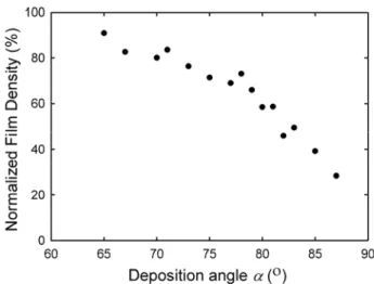
Figure 3 shows the normalized density (density compared to films grown at α = 0°) of the biaxial post layer as a function of deposition angle measured by the optical model. As expected the film density decreases as the deposition angle is increased. This is due to increased self-shadowing that occurs at higher deposition angles, thus increasing the average spacing between nucleation sites. The result is an increase in the ratio of void to film, which decreases the effective index of refraction of the tilted column layer. The computed values for the three principal indices at a wavelength of λ = 525 nm are given in Fig. 4, and as expected, the values of the principal indices of refraction decrease with deposition angle.
Figure 3: Normalized film density of the biaxial layer as a function of the deposition angle α.
Figure 4: The principal indices of refraction for the biaxial layer of Alq3 at a wavelength of 525 nm.
4.3
Birefringence
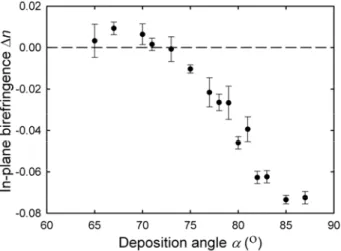
Figure 5 shows the calculated ∆n as a function of deposition angle. A larger index of refraction in the direction parallel to the deposition plane is measured than perpendicular to the deposition plane (np > nx) at deposition
angles α > 70°. This negative in-plane birefringence is opposite to the values previously seen in biaxial film studies of inorganic thin films [4, 15, 16]. A generally increasing magnitude is observed as the deposition angle α is increased, with a maximum negative birefringence of −0.073 ± 0.002 obtained for the film deposited at 85°. The negative value of the in-plane birefringence is due largely to the predominantly circular cross-section of individual Alq3 columns in the direction of column growth, illustrated
in Figure 6(a). The Alq3 columns have diameters in the
approximate range of 40 to 70 nm which remain constant throughout the thickness of the biaxial film layer and do not exhibit the common broadening effects that are present in inorganic GLAD films.
The in-plane anisotropy varies due to the form birefringence of the column cross-sections, which due to the circular nature of the post cross-sections, cause the variation of the column cross-sectional geometry in the substrate plane to vary as a function of the column tilt angle
β. A greater column tilt causes an increase in the length of
the major elliptical axis of the columns in the substrate plane whereas the length of the minor elliptical axis perpendicular to the deposition plane remains unchanged and equal to the post diameter.
The individual post morphology deteriorated at lower deposition angles as the individual posts began to chain together and coalesce, causing the circular cross-sections to merge and a secondary anisotropy to occur in the film perpendicular to the deposition plane as seen in Figure 6(b). This phenomenon caused a change in the form birefringence similar to column broadening seen in inorganic GLAD films, resulting in a decrease in voids between columns and thus an increase in the refractive index perpendicular to the deposition plane. This leads to the positive in-plane birefringence values observed in Figure 5 for α < 70°. The column melding effect coupled with the smaller column tilt angle reduced the negative in-plane birefringence at lower deposition angles. This was observed to be largest in the films deposited at 67° and 70° which measured the largest positive birefringence values. The maximum in-plane positive birefringence occurs at a similar angle to that observed for inorganic biaxial thin films [4].
Figure 5: In-plane birefringence, ∆n, shown as a function of deposition angle.
Figure 6: SEM of the film deposited at (a) α = 85° and (b) α = 67° as viewed along the direction of the columns. The arrows indicate the direction of the incoming vapour flux.
5
CONCLUSION
Porous biaxial thin films composed of organic Alq3
slanted columnar posts have been fabricated and characterized using variable angle spectroscopic ellipsometry and the Bruggeman effective medium approximation. The Alq3 films exhibited expected column
angle and density behaviour in relation to the deposition angle. A negative in-plane birefringence has been observed in GLAD produced thin films with a maximum value of −0.073 ± 0.002 observed. Negative in-plane birefringence is a result of the predominantly circular cross-section of the Alq3 columnar posts that control the form birefringence as a
function of the column tilt, without the detriment of secondary anisotropic effects such as column broadening.
ACKNOWLEDGEMENTS
The authors would like to thank George Braybrook (Department of Earth and Atmospheric Sciences at the University of Alberta) for his excellent SEM work. This research was supported by the Natural Sciences and Engineering Research Council (NSERC), the NRC National Institute for Nanotechnology, the Informatics Circle of Research Excellence (iCORE), Micralyne Inc, and the University of Alberta NanoFab.
REFERENCES
[1] P. C. P. Hrudey, K. L. Westra, and M. J. Brett,
Advanced Materials, vol. 18, pp. 224-228, 2006.
[2] P. C. P. Hrudey, B. Szeto, and M. J. Brett, Applied
Physics Letters, vol. 88, pp. 251106, 2006.
[3] I. Hodgkinson, Q. H. Wu, B. Knight, A.
Lakhtakia, and K. Robbie, Applied Optics, vol. 39, pp. 642-649, 2000.
a) b)
[4] I. Hodgkinson, Q. H. Wu, and S. Collet, AppliedOptics, vol. 40, pp. 452-457, 2001.
[5] K. Robbie and M. J. Brett, Journal of Vacuum
Science and Technology A, vol. 15, pp. 1460-1465,
1997.
[6] S. R. Kennedy, M. J. Brett, H. Miquez, O. Toader, and S. John, Photonics and Nanostructures, vol. 1, pp. 37-42, 2003.
[7] M. M. Hawkeye and M. J. Brett, Journal of
Applied Physics, vol. 100, pp. 044322, 2006.
[8] B. Johs, J. A. Woollam, C. M. Herzinger, J. Hilfiker, R. Synowicki, and C. L. Bungay, SPIE
CR72, 29-58, 1999.
[9] B. Szeto, P. C. P. Hrudey, M. Taschuk, and M. J. Brett, Proc. of SPIE 6135, 2006.
[10] D. E. Aspnes, Thin Solid Films, vol. 89, pp. 249-262, 1982.
[11] J. Gospodyn and J. C. Sit, Optical Materials, vol. 29, pp. 318-325, 2006.
[12] K. Kaminska, A. Amassian, L. Martinu, and K. Robbie, Journal of Applied Physics, vol. 97, pp. 013511, 2005.
[13] R. N. Tait, T. Smy, and M. J. Brett, Thin Solid
Films, vol. 226, pp. 196-201, 1993.
[14] K. D. Harris, D. Vick, T. Smy, and M. J. Brett,
Journal of Vacuum Science & Technology A-Vacuum Surfaces and Films, vol. 20, pp.
2062-2067, 2002.
[15] Y. Taga and T. Motohiro, Journal of Crystal
Growth, vol. 99, pp. 638-642, 1990.
[16] T. Motohiro and Y. Taga, Applied Optics, vol. 28, pp. 2466-2482, 1989.