ATAC: A 1000-Core Cache-Coherent
Processor with On-Chip Optical Network
The MIT Faculty has made this article openly available.
Please share
how this access benefits you. Your story matters.
Citation
Kurian, George et al. “ATAC.” ACM Press, 2010. 477. Web. 9 Dec.
2011. © 2010 Association for Computing Machinery
As Published
http://dx.doi.org/10.1145/1854273.1854332
Publisher
Association for Computing Machinery
Version
Author's final manuscript
Citable link
http://hdl.handle.net/1721.1/67490
Terms of Use
Creative Commons Attribution-Noncommercial-Share Alike 3.0
Appears in Proceedings of Parallel Architectures and Compilation Techniques (PACT), September 2010, Vienna, Austria
ATAC: A 1000-Core Cache-Coherent Processor with
On-Chip Optical Network
George Kurian, Jason E. Miller, James Psota, Jonathan Eastep, Jifeng Liu,
Jurgen Michel, Lionel C. Kimerling, Anant Agarwal
{gkurian, jasonm, psota, eastep, jfliu01, jmichel, lckim, agarwal}@mit.edu Massachusetts Institute of Technology
Cambridge, MA 02139
ABSTRACT
Based on current trends, multicore processors will have 1000 cores or more within the next decade. However, their promise of in-creased performance will only be realized if their inherent scal-ing and programmscal-ing challenges are overcome. Fortunately, re-cent advances in nanophotonic device manufacturing are making CMOS-integrated optics a reality—interconnect technology which can provide significantly more bandwidth at lower power than con-ventional electrical signaling. Optical interconnect has the poten-tial to enable massive scaling and preserve familiar programming models in future multicore chips.
This paper presents ATAC, a new multicore architecture with in-tegrated optics, and ACKwise, a novel cache coherence protocol designed to leverage ATAC’s strengths. ATAC uses nanophotonic technology to implement a fast, efficient global broadcast network which helps address a number of the challenges that future multi-cores will face. ACKwise is a new directory-based cache coher-ence protocol that uses this broadcast mechanism to provide high performance and scalability. Based on 64-core and 1024-core sim-ulations with Splash2, Parsec, and synthetic benchmarks, we show that ATAC with ACKwise out-performs a chip with conventional interconnect and cache coherence protocols. On 1024-core evalu-ations, ACKwise protocol on ATAC outperforms the best conven-tional cache coherence protocol on an electrical mesh network by 2.5x with Splash2 benchmarks and by 61% with synthetic bench-marks.
Categories and Subject Descriptors
C.1.2 [Processor Architectures]: Multiple Data Stream Archi-tectures (Multiprocessors)—Multiple-instruction-stream, multiple-data-stream processors, Interconnection architectures
General Terms
Design, Performance
Permission to make digital or hard copies of all or part of this work for personal or classroom use is granted without fee provided that copies are not made or distributed for profit or commercial advantage and that copies bear this notice and the full citation on the first page. To copy otherwise, to republish, to post on servers or to redistribute to lists, requires prior specific permission and/or a fee.
PACT’10,September 11–15, 2010, Vienna, Austria. Copyright 2010 ACM 978-1-4503-0178-7/10/09 ...$10.00.
Keywords
Network-on-Chip, Photonic Interconnect, Cache Coherence
1.
INTRODUCTION
The trend in modern microprocessor architectures is clear: multi-core is here. As silicon resources become increasingly abundant, processor designers are able to place more and more cores on a chip with massive multicore chips on the horizon. Many industry pundits have predicted manycores with 1000 or more cores by the middle of the next decade. But will current processor architectures (especially their interconnection mechanisms) scale to thousands of cores, and will such systems be tractable to program? This paper argues that current multicore architectures will not scale to thousands of cores and introduces ATAC (pronounced ¯a-tack), a new processor architecture that addresses these issues. ATAC inte-grates an on-chip optical broadcast communication network within a mesh based tiled multicore architecture to significantly improve the performance, energy scalability, and ease of programmability of multicore processors [17, 16].
Although Moore’s Law enables increasing numbers of cores on a single chip, the extent to which they can be used to improve per-formance is limited both by the cost of communication among the cores and off-chip memory bandwidth. Although our research is in-vestigating the application of optical technology to both problems, this paper focuses on the on-chip interconnect challenge. As com-putation is spread across multiple cores on a chip, distribution of instructions to the cores, and communication of intermediate values between cores account for an increasing fraction of execution time due to both latency and contention for communication resources. The outlook is particularly dismal for applications that require a lot of global communication operations (e.g., broadcasts to main-tain cache coherence) because each such operation ties up many resources and consumes a lot of energy.
State-of-the-art multicore chips employ one of two strategies to deal with interconnection costs. Small-scale multicores typically use a bus to interconnect cores. This simple design does not scale to large numbers of cores due to increasing bus wire length and contention. Other strategies use point-to-point networks such as the ring employed by the Cell processor [20] or the mesh employed by the Raw microprocessor [23]. These avoid long global wires but have the drawback that communication between distant cores re-quires multiple routing hops and overlapping messages experience significant contention and latency at large numbers of cores.
Aside from interconnect scalability challenges, multicore archi-tectures also face programming challenges. Programmers must spatially and temporally orchestrate computation and
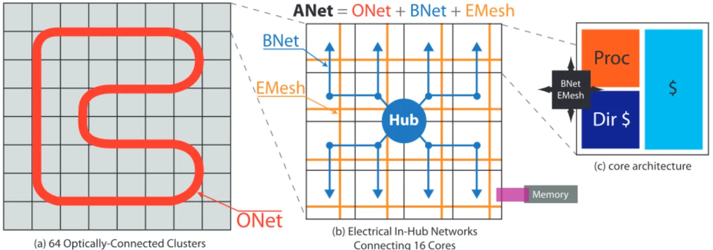
communica-(a) 64 Optically-Connected Clusters (b) Electrical In-Hub NetworksConnecting 16 Cores (c) core architecture
Hub
BNet
ONet
EMesh
Proc
Dir $
$
BNet EMeshANet
=
ONet +
BNet
+
EMesh
Memory
Figure 1: ATAC architecture overview tion to extract high performance from the hardware. Even a simple
function like broadcasting common data to all cores is difficult to perform efficiently. Broadcast and all-to-all communication oper-ations in popular coherence and synchronization protocols present even greater challenges.
The ATAC processor architecture addresses these issues using on-chip optical communications technologies. Optical communi-cations technologies have made tremendous strides toward integrat-ing optoelectronic components with standard CMOS fabrication processes. ATAC leverages these advances to eliminate communi-cation contention using Wavelength Division Multiplexing (WDM). WDM allows a single optical waveguide to simultaneously carry multiple independent signals on different wavelengths. For exam-ple, a single waveguide with the same switching speed as its elec-trical counterpart and with 64 WDM channels would match the bandwidth of a 64-bit electrical bus. Optical waveguides, how-ever, can also transmit data at higher speeds than electrical wires (a function of the index of refraction of the waveguide material for the optical signal; and a function of the RC delays, the dielectric
material (SiO2) surrounding the wires, and the delay of required
repeaters for the electrical signal). This virtually eliminates the need for multiple hops between cores and the resulting contention at large scales. Optical signaling can also use less power (espe-cially compared to long wires) because optical waveguides have relatively low loss and therefore do not require periodic repeaters or high-power drivers.
The ATAC processor is a tiled multicore processor augmented with an optical broadcast network. Each tile is interconnected elec-trically to its neighbors by a mesh network and optically through a global network that is low-latency and contention-free. The optical network consists of a set of optical waveguides that snake through the chip making a continuous loop as shown in Figure 1(a). Optical Hubs transmit data by modulating a laser light source and injecting it into the loop. The signal quickly propagates around the loop and can be received by all of the other Hubs in a single operation. Thus every message on the optical network has the potential to be an ef-ficient global broadcast. Filtering at the receiving Hubs is used to limit the scope of the message for multicast or unicast messages.
ATAC’s optical network is designed to provide the programming benefits of a bus interconnect while mitigating the scalability draw-backs. Like a bus, the optical network supports broadcast and provides uniform latency between network endpoints – two impor-tant properties for programming simplicity. Unlike a bus, it allows multiple senders to communicate simultaneously and without
con-tention and is scalable to thousands of cores. Optical networks in Corona [10] and other works are tailored for point-to-point mes-sages which do not confer these advantages.
This paper introduces ACKwise, a novel directory-based cache coherence protocol that provides high performance and scalability on any large-scale optical interconnection network, such as ATAC’s. Using simulations from Splash2, Parsec and synthetic benchmarks, we show that the ATAC network coupled with ACKwise out-performs a chip consisting of an electrical mesh network of similar area and conventional directory-based cache coherence protocols.
The remainder of this paper is organized as follows. Section 2 gives nanophotonics background, focusing on physical constraints imposed on the ATAC architecture. Section 3 provides an overview of the ATAC architecture, including its processing, communication, and memory mechanisms. Section 4 introduces the ACKwise cache coherence protocol. Section 5 evaluates the ATAC architecture us-ing the ACKwise protocol and provides a preliminary set of results using Splash2, Parsec and synthetic benchmarks focusing on how ATAC enables high performance cache coherence across 64 and 1024 cores. Section 6 follows with a detailed discussion of related work, and Section 7 concludes the paper.
2.
OPTICAL DEVICES BACKGROUND
Advances in electronic-photonic integration have enabled opti-cal interconnect technologies with greater integration, smaller dis-tances, and higher bandwidths [21], [22], [15], [28]. Further, recent research [19] has shown that optical devices can be built using stan-dard CMOS processes, thereby allowing optics to replace global wires and on-chip buses [1].
This section presents a brief overview of these CMOS compati-ble devices and their constraints. The key elements in a nanopho-tonic network such as the one employed by the ATAC chip include: the “optical power supply” light source; waveguides to carry opti-cal signals; filters and modulators to place signals into the waveg-uides; and detectors to receive signals from the waveguides. This section discusses each of these components and describes the com-plete path for transmitting data optically.
In ATAC the light source, or “optical power supply”, is generated by off-chip lasers and coupled into an on-chip waveguide. On-chip light sources exist, but consume large quantities of precious on-chip power and area. The power consumption of an off-on-chip laser is roughly 1.5 W, with 0.2 W of optical power ending up in the on-chip waveguide.
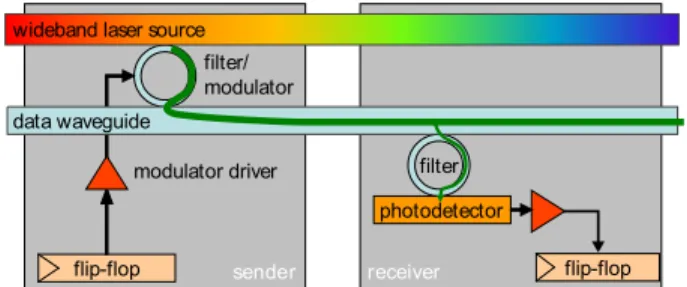
sende receive flip-flop flip-flop filter photodetector filter/ modulator modulator driver data waveguide
wideband laser source
r r
Figure 2: Optical transmission of a single bit
guide and confine light by a combination of a high-refractive-index material on the inside of the waveguide and a low-refractive-index material on the outside (the cladding). Waveguides can be made out of either silicon (Si) or polymer. Due to the fact that Si waveg-uides can be packed onto a chip at much higher densities and that modulators for Si can be made much more compactly, the ATAC design employs Si waveguides. These waveguides can be manu-factured in a standard CMOS process, as both the waveguide and cladding materials are commonly used elsewhere. ATAC requires waveguides with losses of less than 0.3dB/cm and total power ca-pacity of about 10 mW, both of which are achievable with Si.
The optical filter is a ring resonator that couples only a specific wavelength from the power supply waveguide to the data waveg-uide. The exact wavelength, as well as the spacing between wave-lengths, is determined by the ring resonator dimensions and is fixed during manufacturing. Limited tuning can be achieved by chang-ing the rchang-ing’s temperature or by injectchang-ing charge into the rchang-ing. The modulator is an optical device that imprints a digital signal on the light extracted by the filter by varying the absorption in the de-vice. Modulators are used to translate an electrical signal (ampli-fied by the modulator driver) into an optical signal, and can there-fore be thought of as an “optical switch”, placing values onto op-tical waveguides. The modulators are Ge based electro-absorption modulators with integrated filters. The ring resonators are not used for modulation but just for wavelength filtering. It is assumed that athermal design [31] is implemented, so that the rings do not need to be tuned. The modulators used in the ATAC design have char-acteristics that are expected to be reached by designs available in
2012: insertion loss of 1dB; area less than 50 µm2; modulation
rate of 1 Gbps; energy required to switch less than 25 fJ; and power consumption of 25 µW at 1 GHz [14].
At the receiving end of a waveguide, additional components are used to receive the signal and convert it to an electrical signal. An additional optical filter is used to extract light of a particular wave-length from the data waveguide and transfer it to a photodetector. The filter can be designed to extract any fraction of the total sig-nal by adjusting the size of the gap between the waveguide and the filter. The photodetector is an extremely sensitive optical device which absorbs photons and outputs an electrical signal. The pho-todetector proposed for ATAC has a responsivity of greater than 1 Amp/Watt and 3dB bandwidth performance at 1 GHz. It has
an area footprint of less than 20 µm2. Furthermore, the expected
capacitance of the photodetector is less than 1 fF [7]. In current technology nodes, the output of the photodetector would need to be amplified by a power-hungry TIA (transimpedance amplifier) be-fore it could be used to drive a digital circuit. However, starting with the 22nm node, the smaller transistor input capacitances will allow the photodetector to directly drive a digital circuit, greatly reducing power consumption.
Figure 2 puts all of these elements together, showing how one bit
is transmitted from a flip-flop of one core to a flip-flop of another core. In this figure, the core on the left shows the components rel-evant to sending and the core on the right shows the components relevant to receiving; however, in the actual chip all cores would contain both sets of components. From end to end, the process for sending a bit on the ATAC’s optical network is as follows. The flip-flop signals the modulator driver to send either a 0 or a 1. The mod-ulator driver, which consists of a series of inverter stages, drives the modulator’s capacitive load. The modulator couples light at its
pre-tuned wavelength λi from the optical power source and encodes
either a 0 or 1 onto the data waveguide. The optically-encoded data signal traverses the waveguide at approximately one-third the speed of light and is detected by a filter that is also tuned to
wave-length λi. Photons are detected by the photodetector and received
by a flip-flop on the receiver side. Note that Figure 2 shows where a TIA would be needed to amplify the photodetector output, even though it would not be necessary for an ATAC chip since ATAC targets the 16nm technology node.
3.
ARCHITECTURE OVERVIEW
As previously illustrated in Figure 1, the ATAC processor uses a tiled multicore architecture combining the best of current scalable electrical interconnects with cutting-edge on-chip optical commu-nication networks. The ATAC architecture is targeted at 1000-core chips implemented in a 16nm process. However, it can also be scaled down to smaller chips. In this paper we describe and evalu-ate 64- and 1024-core versions. We first review the baseline elec-trical architecture, and then describe how it is augmented with the optical interconnect.
The underlying electrical architecture consists of a 2-D array of processing cores connected by a conventional point-to-point, packet-switched mesh network (called the EMesh) like those seen in other multicore processors [23, 12, 11]. Each core in ATAC contains a single- or dual-issue, in-order RISC pipeline with data and instruction caches (Figure 1(c)). ATAC uses a novel directory-based cache coherence scheme with a portion of the directory in each core (see Section 4).
To this electrical baseline, we add a global optical interconnect— the ANet—based on state-of-the-art optical technology. Whereas the EMesh is ideal for predictable, short-range point-to-point com-munication, the ANet provides low-latency, energy-efficient global and long-distance communication. The key component of the ANet is the all-optical ONet shown in Figure 1(a). In the 1024-core
ATAC architecture (called ANet1024), cores are grouped into 64
“clusters”, each containing 16 cores. Each cluster contains a single ONet endpoint called a Hub. The Hub is responsible for interfac-ing between the optical components of the ONet and the electrical components within a cluster. The ATAC architecture can be scaled down by reducing the number of cores with each cluster. A 64-core
chip (called ANet64) would connect each core directly to a Hub.
In ANet1024, individual cores are connected to the Hub in two
ways: data going from a core to the hub uses the standard EMesh (described above); data going from the Hub to the cores uses the BNet, a small electrical broadcast network (Figure 1(b)). In the 22nm node, the clusters are small enough that a flit can travel from the Hub to all cores in a cluster within one clock cycle. Because the BNet is dedicated to broadcasts, it is essentially a fanout tree and requires no routers, crossbars, or internal buffering. It requires only a small amount of buffering and arbitration at the Hub and receiving buffers at the leaves. We estimate that a BNet requires less than one-eighth the area of a full EMesh of the same bitwidth.
The ANet1024uses a 128-bit wide ONet (128 optical waveguides
128-bit wide BNets. The Hub ar128-bitrates between the two BNets using a static policy: packets sent from clusters with even number IDs on the first BNet and odd number IDs on the second BNet. Together,
the ONet, EMesh and BNet form the complete ANet1024.
3.1
ONet Optical Network
The key to efficient global communication in a large ATAC chip is the optical ONet. The ONet provides a low-latency, contention-free connection between a set of optical endpoints called Hubs. Hubs are interconnected via waveguides that visit every Hub and loop around on themselves to form continuous rings (Figure 1(a)). Each Hub can place data onto the waveguides using an optical mod-ulator and receive data from the other Hubs using optical filters and photodetectors. Because the data waveguides form a loop, a signal sent from any Hub will quickly reach all of the other Hubs. Each Hub’s filters are tuned to extract approximately 1/64th of the signal, allowing the rest to pass on to the downstream Hubs. Thus every transmission on the ONet is actually a fast, efficient broadcast.
The ONet uses wavelength division multiplexing (WDM) to cir-cumvent contention. Each Hub has modulators tuned to a unique wavelength to use when sending and contains filters that allow it to receive signals on all of the other wavelengths. This eliminates the need for arbitration in the optical network. Taken together, these features mean that the ONet is functionally similar to a broadcast bus, but without any bus contention.
WDM is a key differentiator of the ATAC architecture from a per-formance scalability perspective. WDM allows a single waveguide to simultaneously carry bits of many overlapping communications. To contrast, an electrical wire typically carries a single bit. Whereas ATAC may share a single waveguide medium between a large num-ber of simultaneous communication channels, implementing multi-ple simultaneous communication channels in the electrical domain requires additional physical wires. For network operations that are expensive to implement in the electrical domain (such as broad-cast), the ATAC approach greatly improves efficiency.
The broadcast mechanism of the ATAC architecture is another key differentiator. Optical technology provides a way to build fast, efficient broadcast networks whereas electrical mechanisms do not. When using optical components instead of electrical components, signals may travel farther and be tapped into by more receivers be-fore they need be regenerated. With electrical components, regen-eration is accomplished via buffers or sizing-up of transistors for increased drive strength. When these electrical mechanisms are ex-tensively employed, as they would be in a large electrical broadcast network, it leads to high energy consumption and poor scaling.
Besides broadcasts, optical technology also allows efficient long-distance point-to-point communication. Initiating an optical signal (i.e., switching the modulator) requires more energy than switch-ing a short electrical wire. However, once generated, the optical signal can quickly travel anywhere on the chip without the need for repeaters. According to our estimates of future optical tech-nology, the on-chip energy required to send data on the ANet is approximately 300 fJ/bit and the signal could be received by all Hubs within 3 ns. An electrical signal, on the other hand, would re-quire approximately 94 fJ/bit/mm and about 1 ns per hop in a mesh network. Since cores in a 1000-core chip will be a little less than
1 mm2, we estimate that it will be more efficient to send an
elec-trical signal if the destination is less than four hops away and an optical signal otherwise. To avoid wasting power and resources de-livering these unicast messages to all cores, ATAC includes filtering at the receiving Hubs and cores. Packets labeled as intended for a single core are only rebroadcast on the BNet of the cluster
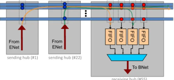
contain-sending hub (#1) sending hub (#22)
FIFO FIFO FIFO FIFO
From ENet To BNet From ENet receiving hub (#55)
Figure 3: Hub-to-hub communication over the ONet ing that core. In addition, the other cores in that cluster will drop the packet immediately, rather than processing it.
The ATAC architecture was carefully designed taking into ac-count the physical limitations and constraints of both the optical (see Section 2) and electronic devices. Based on these constraints, the ONet as described above should scale to at least 64 (and possi-bly as many as 100) Hubs. This limit is based on several factors: 1) the total range of wavelengths over which the optical devices can be tuned divided by the minimum spacing between wavelengths, 2) the total amount of optical power a waveguide can carry divided by the minimum amount that each photodetector needs to receive to reliably register a signal, and 3) the maximum length of a waveg-uide based on the acceptable propagation losses.
These limits can be overcome using multiple waveguides and di-viding the communication channels between them. However, even-tually the area needed for the optical components will become the limiting factor. The ONet’s optical components and photonic in-terconnect can be placed on a separate layer in the CMOS stack, and can therefore overlap the electrical components to which they
connect. However, for a 400 mm2 chip, the entire area would be
consumed by an ONet with approximately 384 Hubs. Since we be-lieve that chips will eventually grow to thousands of cores, some sharing of Hubs will certainly be needed. Therefore, for the pur-poses of this paper, we take the simple approach and assume that the ONet is limited to 64 Hubs.
Sending data using the ONet is shown in more detail in Figure 3. To provide adequate on-chip bandwidth, the ONet uses a bundle of waveguides, each containing 64 wavelengths. Multiple waveg-uides are used to transmit multiple bits of a word simultaneously. As mentioned previously, wavelengths are unique to each sender. This allows the two Hubs shown to send their data simultaneously without interference. The receiving Hub captures both of the val-ues simultaneously into sender-Hub-specific FIFOs. These valval-ues are then propagated to the cores using the BNet. The ONet con-tains 128 waveguides for data, one for backwards flow control, and several for metadata. The metadata waveguides are used to indicate a message type (e.g., memory read, barrier, raw data) or a message tag (for disambiguating multiple messages from the same sender).
3.2
Cache Subsystem
The data caches across all cores on the ATAC chip are kept co-herent using a directory-based coherence protocol called ACKwise described in more detail in Section 4. The directory is distributed evenly across the cores. Furthermore, each core is the “home” for a set of addresses (the allocation policy of addresses to homes is statically defined).
3.3
External Memory Subsystem
When cores need to communicate with external memory, they do so via several on-chip memory controllers. Each cluster has
State G Sharer 1 Sharer 2 … Sharer k
Figure 4: Structure of an ACKwisekdirectory entry
one core replaced by a memory controller. After receiving requests through the ANet, the memory controller communicates with exter-nal DRAM modules through I/O pins. Replies are then sent back to the processing cores through the ANet. Other ATAC chips with different memory bandwidths are possible by varying the number of cores replaced by memory controllers.
The primary task of the memory controller is to translate requests from the processing cores into transactions on a memory I/O bus. The choice of I/O bus technology is independent of the on-chip network architecture since the memory controller is performing a translation. However, to support the large number of memory con-trollers needed for a 1000-core chip, we assume that the connection to memory is optical as well.
A detailed design for an optical memory subsystem is left to fu-ture work. However, we can assume that an optical memory bus would consist of some number of on-chip waveguides that are cou-pled to external fibers, effectively creating optical “pins.” Each op-tical pin could carry up to 64 wavelengths of light at speeds of up to 20 GHz. The actual transmission speed would likely be lim-ited by design trade-offs in the electrical circuits driving the op-tical components. We estimate that opop-tical I/O pins operating at 5 GHz (yielding 40 GB/s of bandwidth) should be practical. Thus each off-chip memory bus can be implemented using a single op-tical pin. This makes it pracop-tical to integrate the large number of memory controllers needed to meet the bandwidth needs of future 1000-core chips.
4.
CACHE COHERENCE PROTOCOL
This section presents ACKwise, a novel cache coherence protocol derived from a MOESI-directory based protocol [26]. Each di-rectory entry in this protocol, as shown in Figure 4 is similar to one used in a limited directory scheme [2] but with a few modi-fications. The 3 fields in each directory entry are as follows: (1) State: This field specifies the state of the cached block(s) asso-ciated with this directory entry (one of the MOESI states); (2) Global(G): This field states whether the number of sharers for the cache block exceeds the capacity of the sharer list. If so, a broadcast is needed to invalidate all the cached blocks correspond-ing to this address when a cache demands exclusive ownership;
(3) Sharer1−Sharerk: These fields represent the sharer list. The
ACKwise protocol which holds the identities of a maximum of k
sharers is denoted as ACKwisek.
When the number of sharers exceeds k, the global(G) bit is set so that any number of sharers beyond this point can be
accommo-dated. Once the global(G) bit is set, the Sharerk field holds the
total number of sharers. The Sharer1−Sharerk−1 fields still hold
the identity of k − 1 distinct sharers.
4.1
Operation of the ACKwise
kProtocol
When a request for a shared copy of a cache block is issued, the directory controller first checks the state of the cache block in the directory cache. (a) If the state is Invalid(I), it forwards the request to the memory controller. The memory controller fetches the cache block from memory and sends it directly to the requester. It also sends an acknowledgement to the directory. The directory changes the state of the cache block to Exclusive(E) and sets the
Sharer1 field to the ID of the requester. (b) If the state is one of
the valid states (i.e., one of MOES), it forwards the request to one of the sharers. The sharer forwards the cache block directly to the
requester and sends an acknowledgement to the directory. Appro-priate state changes happen in the directory according to the rules of the MOESI protocol [26]. The directory controller also tries to add the ID of the requester to the sharer list. This is straightforward if the global(G) bit is clear and the sharer list has vacant spots. If
global(G)bit is clear but the sharer list is full, it sets the global(G)
bit and stores the total number of sharers (in this case, k + 1) in the
Sharerkfield. If the global(G) bit is already set, then it increments
the number of sharers by one.
When a request for an exclusive copy of a cache block is issued, the directory controller first checks the state of the cache block in the directory cache. (a) If the state is Invalid(I), the sequence of ac-tions followed is the same as that above except that the state of the cache block in the directory is set to Modified(M) instead of Exclu-sive(E). (b) If the state is one of the valid states (i.e., one of MOES), then the directory controller performs the following 2 actions: (i) It forwards the request to one of the sharers. (ii) If the global bit is clear, it sends unicast invalidation messages to each core in the sharer list. Else, if the global bit is set, it broadcasts an invalidation message (to all the cores in the system). Now, the sharer which receives the forwarded request sends the cache block directly to the requester, invalidates the block and acknowledges the directory. The other sharers invalidate their cache blocks and acknowledge the directory. The directory controller expects as many
acknowl-edgements as the number of sharers (encoded in the Sharerkfield
if the global(G) bit is set and calculated directly if the global(G) bit is clear). After all the acknowledgements are received, the di-rectory controller sets the state of the cache block to Modified(M),
the global(G) bit to 0 and the Sharer1 field to the ID of the
re-quester. Due to the broadcast capabilities of ATAC as described in Section 3, the sending of broadcast messages can be achieved
easily. In addition, the ACKwisekprotocol requires only as many
unicast acknowledgements as a full-map directory-based protocol. Hence the name ACKwise since the protocol intelligently tracks the number of sharers of a cache block and requires acknowledgements from only the actual sharers on an invalidation broadcast message. Silent evictions are not supported in the ACKwise protocol since the directory should always have an accurate count of the number of sharers of a cache line for correct operation. However, disallowing silent evictions is not found to be detrimental to the performance of the ACKwise protocol because: (1) the additional coherence mes-sages do not lie on the critical path of load or store misses and hence do not directly affect the average memory latency and thereby pro-cessor performance; (2) these messages do not include data and hence contribute only a small percentage to the overall network traffic and thereby do not really affect the network latency.
5.
EVALUATION
The purpose of this section is to demonstrate: (1) The capabil-ities of the ATAC network (ANet) over a pure electrical mesh net-work (EMesh), and (2) The performance advantages of using the
ACKwisekprotocol over the DirkBand DirkNBlimited
directory-based cache coherence protocols [2]. DirkBis a limited directory
based protocol which broadcasts once the capacity of the sharer list is exceeded and collects acknowledgements from all the cores
in the system. ACKwisek on the other hand, intelligently tracks
the number of sharers once the capacity of the sharer list is ex-ceeded and needs acknowledgements from only the actual sharers
of the data on a broadcasted invalidation. DirkNBalways ensures
that the number of sharers of a cache line is less than the capac-ity of the sharer list. k denotes the number of hardware sharers in each of the above protocols. This section evaluates the perfor-mance of Splash2 and Parsec benchmarks as well as synthetic
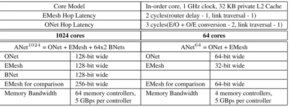
ap-Core Model In-order core, 1 GHz clock, 32 KB private L2 Cache EMesh Hop Latency 2 cycles(router delay - 1, link traversal - 1)
ONet Hop Latency 3 cycles(E/O + O/E conversion - 2, link traversal - 1) 1024 cores 64 cores
ANet1024= ONet + EMesh + 64x2 BNets ANet64= ONet + EMesh ONet 128-bit wide ONet 64-bit wide EMesh 128-bit wide EMesh 32-bit wide BNet 128-bit wide
EMesh for comparison 256-bit wide EMesh for comparison 64-bit wide Memory Bandwidth 64 memory controllers, Memory Bandwidth 4 memory controllers,
5 GBps per controller 5 GBps per controller
Table 1: Target System Architecture Configuration Parameters plications on 64 and 1024 cores using six combinations of on-chip
networks and cache coherence protocols: (a) ANet-ACKwisek, (b)
ANet-DirkB, (c) ANet-DirkNB, (d) EMesh-ACKwisek, (e)
EMesh-DirkBand (f) EMesh-DirkNB. Results demonstrate the advantages
of using ANet over EMesh due to its higher bandwidth, lower la-tency and broadcast capabilities as well as the performance benefits
of the ACKwisekprotocol over the DirkBand DirkNBprotocols.
5.1
Methodology
The Graphite [18] distributed multicore simulator is used for all
evaluations in this section. For the 64 core simulations, the ANet64
network is compared to a 64-bit wide electrical mesh network. For
the 1024 core simulations, the ANet1024network is compared to a
256-bit wide electrical mesh network. The above comparisons are justified because the optical components of the ONet can be placed on a separate layer, thereby making the ONet have only few area requirements for receiver-side electrical buffering and arbitration. In addition, the area of a 128-bit wide BNet is roughly one-eighth the area of a 128-bit wide electrical mesh (see Section 3).
Table 1 summarizes the detailed target architectures. In ANet64,
short unicast messages less than four hops away are sent on the EMesh (due to energy considerations as described in Section 3) while broadcasts and long unicast messages are sent on the ONet.
In ANet1024intra-cluster communication occurs through the EMesh
network while inter-cluster communication is carried out using the EMesh, ONet and BNet networks. Small private L2 cache sizes were assumed due to the small working set sizes of Splash2 bench-marks. All the references to EMesh in the remaining part of the evaluation section refer to the respective 64-core 64-bit wide and 1024-core 256-bit wide pure electrical mesh networks against which
the ANet64and ANet1024networks are compared.
5.2
Parsec and Splash2 Benchmarks
Nine applications from the Splash2 benchmark suite and three applications from the Parsec benchmark suite are simulated on 64 and 1024 cores using the 6 combinations of cache coherence pro-tocols and networks mentioned previously.
5.2.1
64 cores
The configurations ANet-Dir64NBand ANet-Dir64Bare expected
to show the same performance as ANet-ACKwise64since the
direc-tory type of the cache coherence protocol does not play a role when the number of hardware sharers is equal to the number of cores
sim-ulated. Similarly, the performance of EMesh-ACKwise64,
EMesh-Dir64NBand EMesh-Dir64Bare expected to be the same. In the
following discussion, ANet refers to ANet64described in Table 1.
Figure 5 plots the performance of the twelve benchmarks
ob-served when running with the DirkNB cache coherence protocol
on the ANet and EMesh networks. The performance is plotted as a function of the number of hardware sharers (k). Results are
nor-malized to the performance observed when running with
EMesh-Dir2NB. With the DirkNB protocol, ANet is observed to
outper-form EMesh at all values of k and the peroutper-formance difference is
ob-served to decrease with increasing values of k. ANet-Dir2NB
out-performs EMesh-Dir2NB by 30.9% while ANet-Dir64NB
outper-forms EMesh-Dir64NB by 12.8%. The performance of the DirkNB
protocol is also observed to highly sensitive to the number of hard-ware sharers. The performance is extremely poor at low numbers of sharers and gradually improves as the number of sharers is
in-creased. On the ANet network, Dir64NB outperforms Dir2NB by
an average of 2.63x and a maximum of 5.51x (in water-spatial). On
the EMesh network, Dir64NB outperforms Dir2NB by an average
of 3.04x and a maximum of 8.29x (also in water-spatial).
The above results can be understood by observing Figure 8 which plots the cache miss rates of the benchmarks when run with the
DirkNB protocol. The cache miss rates are observed to decrease as
the number of hardware sharers (k) is increased. Hence, the perfor-mance increases with an increase in the value of k. High cache miss rates occur at low values of k due to the presence of a large number of true shared reads in these benchmarks. (A core is said to perform a true shared read when it reads from an address that is cached by at least another core in the system). The true shared reads lead to the occurrence of frequent invalidations because a large number of cores try to simultaneously read globally shared data and evict each others’ cache lines in the process due to the restriction on the num-ber of hardware sharers. The rate of increase of performance with k is directly correlated to the rate of decrease of cache miss rates with k as can be observed from Figures 5 and 8. This explains why benchmarks like water_spatial show a speedup of 8.29x on EMesh while others like lu_non_contiguous show very little speedup (9% on EMesh) when the number of hardware sharers is increased from 2 to 64. The cache miss rates of all benchmarks except canneal decrease with increasing k. Canneal has a very large working set with almost zero temporal locality. Due to this, any cache coher-ence protocol used with canneal is expected to show a constant miss rate given a particular cache size and cache line size.
At low values of k, since the cache miss rates are high, the net-work traffic intensity is also high. The bisection bandwidth of
ANet64 is proportional to N while that of EMesh is proportional
to√N (N being the number of cores). Hence, ANet is more
ca-pable of handling higher network loads than the EMesh network. This explains why the performance difference between ANet and EMesh decreases with an increase in k and proves that ANet out-performs EMesh even with a purely unicast traffic pattern.
Figure 6 shows the performance of seven benchmarks when
us-ing the DirkB protocol on the ANet and EMesh networks. The
results here are also normalized to the performance of
EMesh-Dir2NB. The DirkB protocol shows less performance sensitivity
0 1 2 3 4 5 6 7 8 9 Sp ee du p ov er E Me sh -‐D ir( 2) N B
Dir(k)NB Performance: ANet and EMesh
64 cores k = 2 k = 3 k = 4 k = 8 k = 16 k = 32 k = 64 0 0.2 0.4 0.6 0.8 1 1.2 1.4 1.6 1.8 Sp ee du p ov er E Me sh -‐D ir( 2) N B k = 2 k = 3 k = 4 k = 8 k = 16 k = 32 k = 64Figure 5: Performance of Splash2 and Parsec benchmarks when using the DirkNB protocol on the ANet and EMesh networks.
Results are normalized to the performance of EMesh-Dir2NB. The number of hardware sharers are varied as 2, 3, 4, 8, 16, 32 and
64. The x-axis values take the form benchmark - network. A and E stand for ANet and EMesh networks respectively.
the twelve benchmarks evaluated, Dir64B outperforms Dir2B by
an average of 10.7% and a maximum of 21.3% (in barnes) on the
ANet network. On the EMesh network, Dir64B outperforms Dir2B
by an average of 13.2% and a maximum of 30.7% (also in barnes). The ANet network is observed to outperform the EMesh network at all values of k. On an average, ANet has a speedup of 14.1% over EMesh. The performance difference between ANet and EMesh is observed to slightly drop with increasing values of k. For the five benchmarks not shown in Figure 6, the performance speedup when the number of hardware sharers is increased from 2 to 64 is < 6% for both the ANet and EMesh networks.
A DirkB protocol adversely affects the performance of the
sys-tem when cache lines are widely shared and writes occur frequently to the widely shared cache lines. When a write occurs to a cache line that is shared by more than k cores, the following two types of messages are generated: (a) an invalidation broadcast message (from the sender core to all the cores in the system), and (b) N uni-cast messages (generated as acknowledgements to the invalidate message) from all cores in the system to the sender core (N is
the number of cores). Since ANet64 possesses a specialized
op-tical broadcast network (ONet), the broadcast message is handled efficiently. It does not affect the network load since the ONet net-work is contention-free. However, it does slightly increase the con-tention delay at the receiving core since there needs to be arbitra-tion among the different messages destined for the same core at the receiving network interface. Since EMesh does not possess a spe-cialized broadcast network, a broadcast is realized using N unicast
messages directed from the sender core to all the other cores on the chip. These unicast messages raise the network load of the EMesh network significantly. On the other hand, the N unicast messages generated as acknowledgements raise the network load of both the ANet and EMesh networks. These N unicast messages have to be generated even if much fewer cores have cached the data. The invalidation broadcast message along with the acknowledgement messages account for the increase in performance when the num-ber of hardware sharers is increased from 2 to 64.
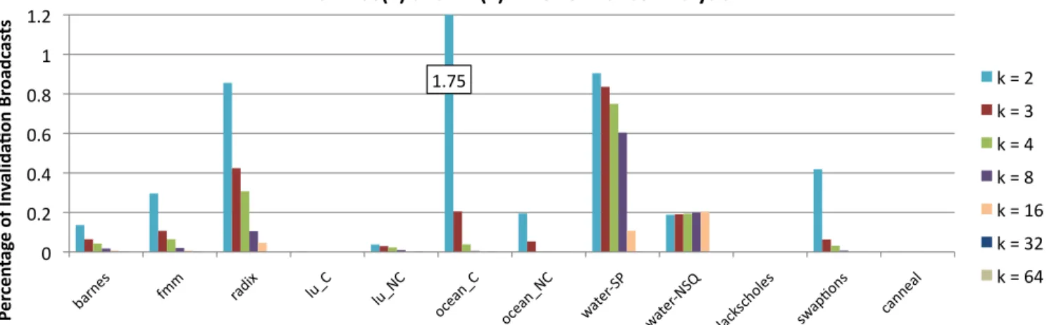
Figure 9 shows the percentage of cache misses that lead to in-validation broadcast messages in the benchmarks evaluated. Al-though it is difficult to quantify the exact dependence of perfor-mance on the amount of broadcast traffic due to other factors such as the burstiness of traffic, working set size, etc, it is nevertheless clear from the explanation above and from Figure 6 that perfor-mance increases steadily with decreasing broadcast traffic (or
in-creasing number of hardware sharers). However, the DirkB
proto-col shows less performance sensitivity to the number of hardware
sharers than the DirkNB protocol. This is because the benchmarks
evaluated exhibit only a small number of true shared writes. (A core is said to perform a true shared write when it writes to an address that is cached by at least another core in the system.) Since the number of true shared writes are small, the invalidation broadcasts and the corresponding acknowledgements do not raise the network contention by a significant amount to adversely affect the over-all system throughput. This fact is obvious from Figure 9 which shows that the percentage of cache misses that turn into
invalida-0 1 2 3 4 5 6 7 8 9 Sp ee du p ov er E Me sh -‐D ir( 2) N B
Dir(k)B Performance: ANet and EMesh
64 cores k = 2 k = 3 k = 4 k = 8 k = 16 k = 32 k = 64Figure 6: Performance of Splash2 and Parsec benchmarks when using the DirkB protocol on the ANet and EMesh networks. Results
are normalized to the performance of EMesh-Dir2NB. The number of hardware sharers are varied as 2, 3, 4, 8, 16, 32 and 64. The
x-axis values take the form benchmark - network. A and E stand for ANet and EMesh networks respectively.
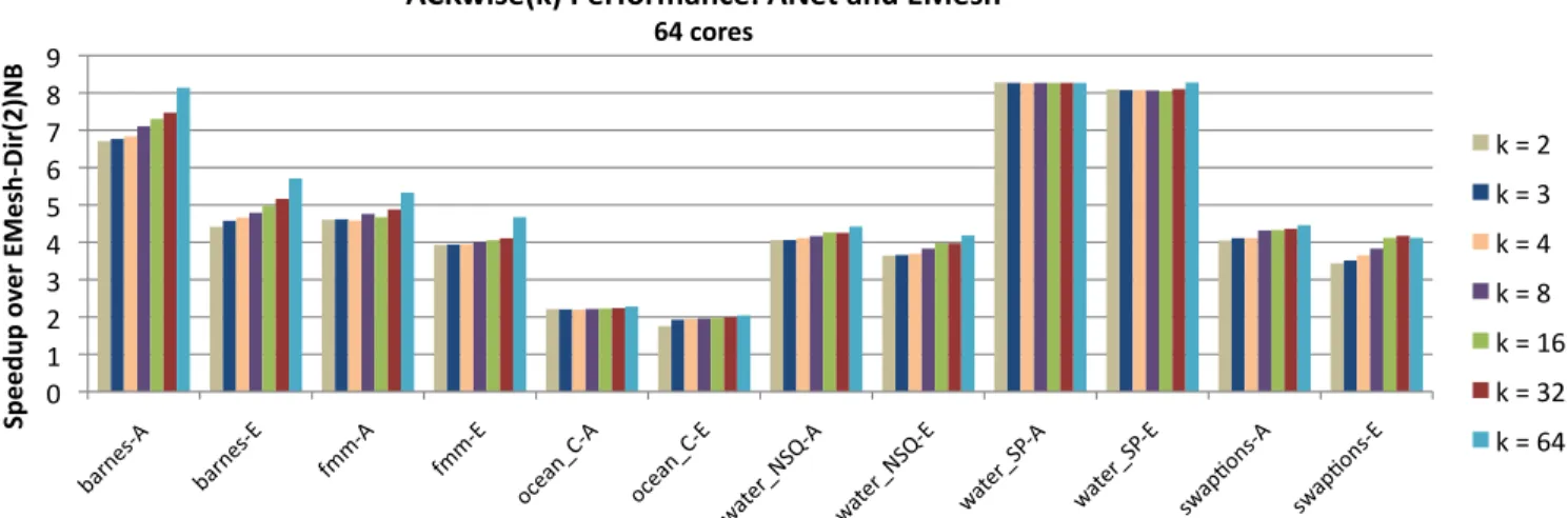
0 1 2 3 4 5 6 7 8 9 Sp ee du p ov er E Me sh -‐D ir( 2) N B
ACKwise(k) Performance: ANet and EMesh
64 cores k = 2 k = 3 k = 4 k = 8 k = 16 k = 32 k = 64Figure 7: Performance of Splash2 and Parsec benchmarks when using the ACKwisekprotocol on the ANet and EMesh networks.
Results are normalized to the performance of EMesh-Dir2NB. The number of hardware sharers are varied as 2, 3, 4, 8, 16, 32 and
64. The x-axis values take the form benchmark - network. A and E stand for ANet and EMesh networks respectively. tion broadcasts is almost always less than 1%. True shared reads,
on the other hand, do not affect the performance of the DirkB
proto-col since the protoproto-col does not place any restriction on the number of cores that can simultaneously cache an address in the read-only state.
Figure 7 shows the performance of the ACKwisek protocol on
the ANet and EMesh networks. The results are again
normal-ized to the performance of EMesh-Dir2NB. The ACKwisek
proto-col shows the least performance sensitivity to the number of hard-ware sharers among the three protocols discussed. On average,
ACKwise64outperforms ACKwise2by 7.9% on the ANet network
and by 11.7% on the EMesh network. Like the previous two proto-cols, the ANet network is observed to outperform the EMesh net-work at all values of k. On average, ANet has a speedup of 14.5% over EMesh. For the six benchmarks that are absent in Figure 7 as
well as for ocean_contiguous, the speedup of ACKwisekwhen the
number of hardware sharers is increased from 2 to 64 is < 3% on ANet and < 4% on EMesh.
Like the DirkB protocol, ACKwisekis not affected by true shared
reads since it allows any number of cores to simultaneously cache an address in the read-only state. The cache miss rates with the
ACKwisekprotocol are observed to be almost independent of the
number of hardware sharers (k). For a true shared write to an
ad-dress that has a sharing degree > k, ACKwisekgenerates the
in-validation broadcast message like the DirkB protocol. The impact
of the invalidation broadcast on the performance of the ANet and
EMesh networks is as described with the DirkB protocol.
How-ever, since ACKwisekintelligently tracks the number of sharers of
a cache line once the capacity of the sharer list is exceeded, it needs acknowledgements from only the actual sharers of the cache line
and not from all the cores in the system as in the DirkB protocol.
In fact, the ACKwisekprotocol only requires as many invalidation
acknowledgements as a full-map directory-based protocol.
For both the ACKwisekand the DirkB protocols, the EMesh
net-work shows a greater performance speedup than the ANet netnet-work when the number of hardware sharers is increased from 2 to 64 since it is not optimized for broadcast traffic. The ANet network, on the other hand, handles both unicast and broadcast traffic more efficiently due to its higher bisection bandwidth and specialized op-tical broadcast network, even at low numbers of hardware sharers.
The above results indicate the presence of a large amount of fre-quently read and sparsely written data in the twelve benchmarks
0 5 10 15 20 25 Ca ch e Mi ss Ra te (%)
Dir(k)NB: Performance Analysis
k = 2 k = 3 k = 4 k = 8 k = 16 k = 32 k = 64
Figure 8: Cache miss rates observed when Splash2 and Parsec benchmarks are run using the DirkNB protocol. The number of
hardware sharers are varied as 2, 3, 4, 8, 16, 32 and 64.
1.75 0 0.2 0.4 0.6 0.8 1 1.2 Pe rc en ta ge o f I nv al id a1 on B ro ad ca st s
ACKwise(k) and Dir(k)B: Performance Analysis
k = 2 k = 3 k = 4 k = 8 k = 16 k = 32 k = 64
Figure 9: Percentage of invalidation broadcasts generated due to memory requests at the directory of a broadcast enabled cache
coherence protocol (ACKwisekor DirkB).
evaluated which is corroborated in [29, 6]. Almost all the bench-marks studied exhibit significant read sharing and little write
shar-ing. Due to this, the DirkNB protocol performs extremely poorly
on both types of networks when compared to the ACKwisekand
DirkB protocols. ACKwisekoutperforms DirkNB by an average
of 69.3% (across all values of k) and a maximum of 2.45x (when
k = 2) on ANet. On EMesh, ACKwisek outperforms DirkNB
by an average of 83.1% and a maximum of 2.73x (when k = 2).
ACKwisekis only found to marginally outperform DirkB, the
rea-son being the low percentage of true shared writes that the
eval-uated benchmarks generate. On average, ACKwisek outperforms
DirkB by 2.1% on ANet by 1.6% on EMesh. In Section 5.3, the
amount of write sharing is varied using a synthetic benchmark and the performance of the cache coherence protocols and networks are evaluated.
5.2.2
1024 Cores
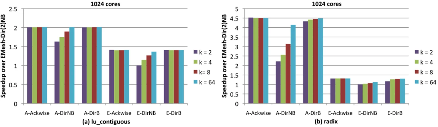
In this section, two applications from the Splash2 benchmark suite, lu_contiguous and radix are simulated on 1024 cores using
the ANet1024and EMesh networks and the 3 cache coherence
pro-tocols described previously. Figure 10 shows the performance re-sults. For radix, ANet outperforms EMesh by an average of 3.3x while for lu_contiguous, ANet outperforms EMesh by an average of 45.7%. The higher speedup of ANet over EMesh for radix is due
to its higher miss rate (6.56% with Ackwise64) when compared to
that of lu_contiguous (0.88% with Ackwise64). Benchmarks with a
high miss rate and thereby a high network load show a greater per-formance benefit when using the ANet network. The perper-formance benefits arise from the lower hop count and greater bisection band-width of the ANet network.
The results with different cache coherence protocols remain the
same as with 64 cores with Ackwisekperforming marginally better
than DirkB and exceedingly better than DirkNB (a maximum of
2.04x with ANet on radix). Also, observe that in the case of radix,
Dir64NB does not have the same performance as Ackwise64. This
is because the cache miss rate for Dir64NB is 7.81% while that
for Ackwise64is 6.56%. Note that with Dir64NB, the number of
hardware sharers, 64 is still less than the number of cores, 1024.
5.3
Synthetic Benchmarks
The Splash2 and Parsec benchmarks are highly structured appli-cations that exhibit extremely good cache behavior as observed in the previous section. They exhibit very high read sharing and lit-tle write sharing which is corroborated in [29, 6]. They are not representative of future multicore workloads that widely share data and exhibit highly unstructured access to them. In this section, we evaluate the performance of a synthetic benchmark that emulates different types of workloads (which exhibit different fractions of read and write sharing) when run with the 6 combinations of cache
0 0.5 1 1.5 2 2.5
A-‐Ackwise A-‐DirNB A-‐DirB E-‐Ackwise E-‐DirNB E-‐DirB
Sp ee du p ov er E Me sh -‐D ir( 2) N B (a) lu_con;guous 1024 cores k = 2 k = 4 k= 8 k = 64 0 0.5 1 1.5 2 2.5 3 3.5 4 4.5 5
A-‐Ackwise A-‐DirNB A-‐DirB E-‐Ackwise E-‐DirNB E-‐DirB
Sp ee du p ov er E Me sh -‐D ir( 2) N B (b) radix 1024 cores k = 2 k = 4 k = 8 k = 64
Figure 10: Performance of the lu_contiguous and radix benchmarks running on 1024 cores with six different combinations of
net-works and cache coherence protocols. The performance is normalized to that observed when using EMesh-Dir2NB. The x-axis values
take the form network - coherence protocol. A and E stand for ANet and EMesh networks respectively.
Instruction Mix:
Non-Memory Instructions 70% Shared Data Access 10% Private Data Access 20% Read-only Fraction of Shared Data {25%, 75%} Private Data per Thread 16 KB Total Shared Data 64 KB (64-core)
1 MB (1024-core) Degree of Application Sharing {1, 2, 4, 8, 16, 32, 64} Instructions Simulated per Thread 1 million (64-core)
100,000 (1024-core)
Table 2: Synthetic Benchmark Characteristics coherence protocols and networks mentioned previously. Experi-ments are done both on 64 and 1024 cores.
The characteristics of the synthetic benchmark used are shown in Table 2. The benchmark is constructed by assigning probabili-ties to instructions and memory access types. Data accessed by the synthetic benchmark is divided into three types: (a) private data, (b) shared data that is only read (read-only shared data) and (c) shared data that is read and written (read-write shared data). Among the instructions that access private data and read-write shared data, the fraction of reads to the fraction of writes is assumed to be 2:1 (be-cause most operations read data from two memory locations, do some computation, and store the result in a third location). The only variables in the synthetic benchmark are the fraction of instructions that access read-only shared data and the degree of sharing of the shared data. For read-only shared data, a sharing-degree d denotes that this data can be read by a total of d sharers and for read-write shared data, degree d denotes that this data can be read/written by a total of d sharers. The amount of private data each core can access is 16 KB and the total amount of shared data is 64 KB and 1 MB for 64-core and 1024-core simulations respectively.
5.3.1
64 Cores
In the following experiments, the network architectures (ANet64
and EMesh) and cache coherence protocols (ACKwisek, DirkBand
DirkNB) studied are as discussed in Table 1. k, the number of
hardware sharers, is fixed at 4. The percentage of instructions that access read-only shared data among those that access shared data is set to either 25% or 75%. The number of application sharers is varied from 1 to 64 in powers of 2.
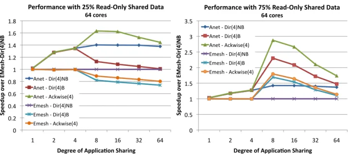
25% Read-Only, 75% Read-Write.
From Figure 11(a), it can be observed that the ACKwise4
proto-col performs best on ANet and the Dir4NB protocol performs best
on EMesh. The ACKwise4 and Dir4B protocols perform poorly
on EMesh. The performance worsens as the degree of applica-tion sharing increases. This is because an increase in the degree of sharing increases the number of broadcast invalidations and a pure electrical mesh performs poorly with a lot of broadcast traffic. The
Dir4NB protocol, on the other hand does not produce any broadcast
traffic. Moreover, the performance penalty of evicting a sharer in order to accommodate another sharer is small for 75% of the data because exclusive requests arrive frequently for cache lines in that address space.
The ANet network on the other hand supports broadcast traffic
efficiently and hence ACKwise4 has the best performance. The
Dir4B protocol still suffers due to the many unicast
acknowledge-ments that have to be sent as a result of a broadcasted invalidation.
The Dir4NB protocol on ANet is found to perform slightly worse
than ACKwise4.
75% Read-Only, 25% Read-Write.
From Figure 11(b), it can be observed that the ACKwise4
pro-tocol performs best on both ANet and EMesh. With 75%
read-only shared data, the Dir4NB protocol performs poorly on both
networks because all sharers of a read-only shared cache line can-not have the data in their private caches at the same time. Hence, the cores accessing read-only shared data keep invalidating each
other frequently. The performance of the Dir4B protocol lies
be-tween that of ACKwise4 and Dir4NB protocol. Even though the
Dir4B protocol achieves the same performance as ACKwise4 on
read-only shared data, it still suffers when there are a sufficient number of broadcast invalidation requests because it has to collect acknowledgements from all the cores for each broadcasted inval-idation. This configuration produces results extremely similar to those produced by the Splash2 and Parsec benchmarks.
5.3.2
1024 Cores
The network architectures ANet1024and EMesh studied are as
discussed in Table 1. In this section we only show results for the synthetic benchmark that has 25% read-only data. The results for the 75% read-only synthetic benchmark are very similar to those shown in Section 5.3.1.
Figure 12 shows that the ACKwise4 protocol coupled with the
ANet network provides the best results. The Dir4B protocol
per-forms extremely poorly on ANet due to its lack of network band-width for the large number of unicast acknowledgements generated by the protocol. This fact is corroborated by the extremely large
0 0.2 0.4 0.6 0.8 1 1.2 1.4 1.6 1.8 1 2 4 8 16 32 64 Sp ee du p ov er E Me sh -‐D ir( 4) N B
Degree of Applica<on Sharing
Performance with 25% Read-‐Only Shared Data 64 cores Anet -‐ Dir(4)NB Anet -‐ Dir(4)B Anet -‐ Ackwise(4) Emesh -‐ Dir(4)NB Emesh -‐ Dir(4)B Emesh -‐ Ackwise(4) 0 0.5 1 1.5 2 2.5 3 3.5 1 2 4 8 16 32 64 Sp ee du p ov er E Me sh -‐D ir( 4) N B
Degree of Applica<on Sharing
Performance with 75% Read-‐Only Shared Data 64 cores Anet -‐ Dir(4)NB Anet -‐ Dir(4)B Anet -‐ Ackwise(4) Emesh -‐ Dir(4)NB Emesh -‐ Dir(4)B Emesh -‐ Ackwise(4)
Figure 11: Performance of the synthetic benchmark running on 64 cores with six different combinations of networks and cache
coherence protocols. The performance is normalized to that of EMesh-Dir4NB.
0 0.2 0.4 0.6 0.8 1 1.2 1.4 1.6 1.8 2 1 2 4 8 16 32 64 Sp ee du p ov er E Me sh -‐D ir( 4) N B
Degree of Applica<on Sharing
Performance with 25% Read-‐Only Shared Data 1024 cores
Anet -‐ Dir(4)NB Anet -‐ Dir(4)B Anet -‐ Ackwise(4) Emesh -‐ Dir(4)NB
Figure 12: Performance of the synthetic benchmark running on 1024 cores with 4 different combinations of networks and cache coherence protocols. The performance is normalized to
that of EMesh-Dir4NB. ACKwise4 and Dir4B protocols
per-form poorly on a pure electrical mesh with this synthetic bench-mark as discussed in Section 5.3.1.
queueing delays observed at the sending Hub with the Dir4B
pro-tocol. Overall, ANet-ACKwise4outperforms the best cache
coher-ence protocol on EMesh (Dir4NB in this case) by an average of
61%. ACKwise4 and Dir4B protocols perform poorly on a pure
electrical mesh with this synthetic benchmark due to the reasons outlined in Section 5.3.1.
From the experiments conducted, it can be concluded that the
DirkB protocol performs well on benchmarks that have widely shared
data which is frequently read and sparsely written. The DirkNB
protocol performs well when the widely shared data is frequently
written. ACKwisekperforms well on both the above types of
bench-marks given the presence of a network with specialized broadcast
support. This paper has built and evaluated such a network using nanophotonic technology.
6.
RELATED WORK
CMOS-compatible nanophotonic devices are an emerging tech-nology. Therefore there have only been a few architectures pro-posed that use them for on-chip communication: Corona [10], the optical cache-coherence bus of Kirman et al [25], and the switched optical NoC of Shacham et al [4].
The Corona architecture primarily differs from ATAC in the way that it assigns communication channels. While Corona assigns a physical channel to each receiver and uses WDM to send multiple bits of a dataword simultaneously, ATAC assigns a physical channel to each sender and uses WDM to carry multiple channels in each waveguide, eliminating contention and the need for arbitration.
Kirman et al [25] design a cache-coherent hierarchical optoelec-tronic bus, consisting of a top-level optical broadcast bus which feeds small electrical networks connecting groups of cores. The de-sign of their network is similar to ATAC but is limited to snooping cache coherence traffic whereas ATAC is composed of a network supporting a general communication mechanism and a coherence protocol (i.e, ACKwise) designed to scale to hundreds of cores.
Shacham et al [4] propose a novel hybrid architecture in which they combine a photonic mesh network with electronic control pack-ets. Their scheme is somewhat limited by the propagation of elec-trical signals since they use an electronic control network to setup photonic switches in advance of the optical signal transmission. It only becomes efficient when a very large optical payload follows the electrical packet. ATAC, on the other hand, leverages the effi-ciencies of optical transmission for even a single word packet.
Pan et al. [27] proposed Firefly, a hybrid electrical-optical net-work architecture. Similar to ATAC, Firefly breaks the chip into clusters of cores interconnected by electrical links. Clusters com-municate via a single-writer multiple-reader optical network. Un-like ATAC, Firefly’s photonic links use an optical crossbar which must be configured by a handshake between the sender and re-ceiver. Firefly partitions its crossbar into multiple smaller logical crossbars to eliminate the need for global arbitration.
Batten et al. [5] take a different approach and use integrated pho-tonics to build a high-performance network that connects cores di-rectly to external DRAM. However, their design does not allow for optical core-to-core communication. An ATAC processor could leverage their design to connect its memory controllers to DRAM. Previous techniques for reducing cache coherence directory stor-age space include using hierarchical directories [30], coarse vec-tors [3], sparse directories [3], chained directories [8], and main-taining limited directories with broadcasting capabilities [2] or soft-ware support [9]. The ACKwise protocol, on the other hand, aug-ments a limited directory based protocol by tracking the number of sharers once the capacity of the sharer list is exceeded. It also borrows the strategy of maintaining a clean owner for reducing the offchip miss rate from cooperative caching [13]. Recent proposals for a cache organization combining the low hit latency of a private L2 cache and the low miss rate of a shared L2 cache [13, 24] are orthogonal to ACKwise and could be used along it.
7.
CONCLUSION
The recent advances of optical technology have certainly inspired confidence in computer architects that optics may very well con-tinue to make its way into smaller and smaller packages; just as optical interconnect has moved from connecting cities to connect-ing data centers, it seems likely that it will soon connect chips and on-chip components.
Overall, this paper presented a novel manycore architecture that scales to 1000 cores by embracing new technology offered by re-cent advances in nanophotonics. This paper also introduced ACK-wise, a novel directory-based cache coherence protocol that takes advantage of the special properties of the ATAC network to achieve high performance. From 64-core and 1024-core evaluations with Splash2, Parsec and synthetic benchmarks, it is observed that the
ACKwiseprotocol on ANet outperforms all other combinations of
networks and cache coherence protocols. On 1024-core
evalua-tions, ACKwise protocol on ANet1024outperforms the best
conven-tional cache coherence protocol on an electrical mesh network by 2.5x with Splash2 benchmarks and by 61% with synthetic bench-marks.
Acknowledgement
This work was partially funded by the National Science Foundation under Grant No. 0811724.
8.
REFERENCES
[1] The International Technology Roadmap for Semiconductors (ITRS) Technology Working Groups, 2008.
[2] A. Agarwal et al. An evaluation of directory schemes for cache coherence. In ISCA, 1988.
[3] A. Gupta et al. Reducing Memory and Traffic Requirements for Scalable Directory-Based Cache Coherence Schemes. In ICPP, 1990.
[4] A. Shacham et al. Photonic NoC for DMA Communications in Chip Multiprocessors. In Hot Interconnects, Aug 2007. [5] C. Batten et al. Building manycore processor-to-dram
networks with monolithic silicon photonics. In Hot Interconnects, pages 21–30, Aug 2008.
[6] C. Bienia et al. The PARSEC Benchmark Suite:
Characterization and Architectural Implications. In PACT, 2008.
[7] D. Ahn et al. High performance, waveguide integrated Ge photodetectors. In Optics Express 15, 3916, 2007.
[8] D. Chaiken et al. Directory-Based Cache Coherence in Large-Scale Multiprocessors. In IEEE Computer, Vol 23, p 49-58, June 1990.
[9] D. Chaiken et al. Limitless Directories: A scalable cache coherence scheme. In ASPLOS, 1991.
[10] D. Vantrease et al. Corona: System Implications of Emerging Nanophotonic Technology. In ISCA, 2008.
[11] D. Wentzlaff et al. On-chip interconnection architecture of the Tile Processor. IEEE Micro, 27(5):15–31, 2007. [12] Intel Corporation. Intel’s Teraflops Research Chip.
http://techresearch.intel.com/articles/Tera-Scale/1449.htm. [13] J. Chang et al. Cooperative Caching for Chip
Multiprocessors. In ISCA, 2006.
[14] J. F. Liu et al. Waveguide-integrated, ultra-low energy GeSi electro-absorption modulators. In Nature Photonics 2, 433, 2008.
[15] J. Michel et al. Advances in Fully CMOS Integrated Photonic Circuits. In Proc. of the International Society for Optical Engineering (SPIE) 6477, p64770P-1-11, 2007. [16] J. Psota et al. ATAC: All-to-All Computing Using On-Chip
Optical Interconnects. In BARC, 1/2007.
[17] J. Psota et al. Improving performance and programmability with on-chip optical networks. In ISCAS, 2010.
[18] J.Miller et al. Graphite: A Distributed Parallel Simulator for Multicores. 2009.
[19] R. Kirchain and L. Kimerling. A roadmap for nanophotonics. In Nature Photonics, 1 (6): 303-305, 2007.
[20] M. Kistler, M. Perrone, and F. Petrini. Cell multiprocessor communication network: Built for speed. IEEE Micro, 26(3):10–23, May-June 2006.
[21] J. F. Liu and J. Michel. High Performance Ge Devices for Electronic-Photonic Integrated Circuits. In ECS
Transactions, Vol 16, p 575-582, 2008.
[22] M. Beals et al. Process flow innovations for photonic device integration in CMOS. In Proc. of the International Society for Optical Engineering (SPIE) 6898, 689804, 2008. [23] M. Taylor et al. Evaluation of the Raw Microprocessor: An
Exposed-Wire-Delay Architecture for ILP and Streams. In ISCA, 2004.
[24] M. Zhang et al. Victim Replication: Maximizing Capacity while Hiding Wire Delay in Tiled Chip Multiprocessors. In ISCA, 2005.
[25] N. Kirman et al. Leveraging Optical Technology in Future Bus-based Chip Multiprocessors. In MICRO, 2006. [26] P. Sweazey et al. A Class of Compatible Cache Consistency
Protocols and their Support by the IEEE Futurebus. In ISCA, 1986.
[27] Y. Pan, P. Kumar, J. Kim, G. Memik, Y. Zhang, and A. N. Choudhary. Firefly: illuminating future network-on-chip with nanophotonics. In ISCA, pages 429–440, 2009. [28] C. Schow. Optical Interconnects in Next-Generation
High-Performance Computers. OIDA 2008 Integration Forum, 2008.
[29] S.Woo et al. The SPLASH-2 Programs: Characterization and Methodological Considerations. 1995.
[30] Y. Maa et al. Two economical directory schemes for large-scale cache coherent multiprocessors. In ACM SIGARCH Computer Arch News, Vol 19, Sept 1991. [31] W. N. Ye, J. Michel, and L. C. Kimerling. Athermal
high-index-contrast waveguide design. IEEE Photonics Technology Letters, 20(11):885–887, 2008.