Vertical Beam Polarization at MAMI
B. S. Schlimmea,∗, P. Achenbacha, K. Aulenbachera, S. Baunacka, D. Bendera, J. Beriˇciˇcb, D. Bosnarc, L. Corread, M. Dehna, M. O. Distlera, A. Essera, H. Fonvieilled, I. Friˇsˇci´cc,1, B. Gutheila, P. Herrmanna, M. Hoeka, S. Kegela, Y. Kohla, T. Kolarb, H.-J. Kreidela, F. Maasa, H. Merkela, M. Mihoviloviˇca, J. M¨ullera, U. M¨ullera, F. Nilliusa,
A. Nucka, J. Pochodzallaa, M. Schotha, F. Schulza, C. Sfientia, S. ˇSircae,b, B. Sprucka, S. ˇStajnerb, M. Thiela, V. Tioukinea, A. Tyukina, A. Webera
aInstitut f¨ur Kernphysik, Johannes Gutenberg-Universit¨at Mainz, D-55099 Mainz, Germany bJoˇzef Stefan Institute, SI-1000 Ljubljana, Slovenia
cDepartment of Physics, University of Zagreb, HR-10002 Zagreb, Croatia dClermont Universit´e, Universit´e Blaise Pascal, F-63000 Clermont-Ferrand, France
eDepartment of Physics, University of Ljubljana, SI-1000 Ljubljana, Slovenia
Abstract
For the first time a vertically polarized electron beam has been used for physics experiments at MAMI in the energy range between 180 and 855 MeV. The beam-normal single-spin asymmetry An, which is a direct probe of higher-order photon exchange beyond the first Born approximation, has been measured in the reaction12C(~e, e0)12C. Vertical polarization orientation was necessary to measure this asymmetry with the existing experimental setup. In this paper we describe the procedure to orient the electron polarization vector vertically, and the concept of determining both its magnitude and orientation with the available setup. A sophisticated method has been developed to overcome the lack of a polarimeter setup sensitive to the vertical polarization component.
Keywords: Electron accelerator, Vertical polarization, Wien filter, Compton polarimeter, Mott polarimeter, Møller polarimeter
1. Introduction
Electron scattering is an excellent tool to study the structure of nucleons and atomic nuclei. In addition to conventional observables like unpolarized scattering cross sections, polarization observables allow novel ac-cess to relevant quantities. In particular, the use of longitudinally polarized electron beams turns out to be very beneficial, and dedicated experiments have been performed at various places. At the Mainz Microtron (MAMI) electron accelerator [1–3], for instance, the electric to magnetic form factor ratios were measured for the proton as well as for the neutron (see [4, 5] and references therein). Moreover, parity-violating (PV) single-spin asymmetries in elastic electron scat-tering were measured to investigate the distribution of
∗Corresponding author.
Email address: [email protected] (B. S. Schlimme)
URL: www.kph.uni-mainz.de (B. S. Schlimme) 1Present address: MIT-LNS, Cambridge MA, 02139, USA
strange quarks within the nucleon [6]. In these PV ex-periments, possible small transverse beam polarization components can lead to significant background through contributions from the beam-normal single-spin asym-metry An. Therefore, the measurement of Anis manda-tory in order to constrain the systematic error. Anitself provides an interesting challenge for theoretical predic-tions, because this observable is a direct probe of multi-photon exchange processes.
A recent measurement of An in elastic scattering off 208Pb revealed a significant disagreement between the data and the prediction [7]. The sources of the disagree-ment are presently not understood and motivate more measurements for target nuclei in the intermediate mass range. In this context, An of carbon has been recently measured at MAMI by using the spectrometer setup of the A1 collaboration [8].
To observe An, the beam polarization vector must have a component normal to the scattering plane, which is spanned by the incident and scattered electron mo-menta. Because the A1 spectrometers accept horizon-tally scattered electrons, the beam polarization must be
set vertical for maximum sensitivity.
Although MAMI does not provide vertical beam po-larization in conventional operation, it was possible to use the existing setup – with minor modifications – to run, for the first time, a high energy vertically polarized beam over several weeks. The direction of the polar-ization was controlled by a combination of two beam line instruments, a Wien filter spin rotator and a dou-ble solenoid. However, an accurate determination of the vertical polarization component was challenging, since a polarimeter sensitive to this polarization component was not available. Hence, we investigated a method to deduce the vertical polarization component from a de-termination of the total beam polarization and the resid-ual horizontal polarization components.
The total beam polarization was measured by using a Møller polarimeter with the beam polarization oriented longitudinally in the experimental hall. After rotation of the polarization vector in the vertical direction, the same polarimeter was used to measure the residual lon-gitudinal polarization component, which should vanish for perfect vertical polarization alignment. The trans-verse horizontal component could be evaluated by mea-suring again with the Møller polarimeter, but at a di ffer-ent beam energy.
Besides dedicated measurements to estimate the con-tribution from false asymmetries to the Møller po-larimeter results, we have also performed polarization measurements with Mott and Compton polarimeters, which are located close to the electron source. A careful comparison provides a powerful test of our understand-ing of systematic effects.
The paper is organized as follows. We briefly review the operating principle of MAMI and its polarized elec-tron source in Sec. 2. In Sections 3 and 4 the precession of the polarization vector in the bending fields of the ac-celerator as well as in the fields of the Wien filter and the double solenoid is described. The results from the alignment procedure at the beginning of the experiment are shown in Sec. 5. Supplementary polarimeter data dedicated to systematic error estimates of the individ-ual polarimeter measurements are evaluated in Sec. 6. Finally, the data from different measurements are com-bined in Sec. 7 and the long-term stability of the polar-ization alignment is considered in Sec. 8. A summary follows in Sec. 9.
2. The polarized electron source at MAMI
The normal-conducting continuous-wave electron ac-celerator MAMI consists of a cascade of three race-track microtrons followed by a harmonic double-sided
microtron. The source of polarized electrons [9, 10] provides longitudinally polarized electrons. They are produced by using a strained GaAs/GaAsP superlattice photocathode illuminated with circularly polarized laser light. The helicity of the electron beam is selected by setting the high voltage polarity of a Pockels cell. Ded-icated tests have been performed to unambiguously de-termine the absolute sign of the helicity at the source by examining the asymmetries of Mott and Møller po-larimeter measurements. By insertion of a λ/2 plate be-tween the laser system and the photocathode, the polar-ization orientation of the electron beam can be reversed. This allows a test of the understanding of systematic ef-fects [11]. The measurements presented in the follow-ing have been taken without the λ/2 plate befollow-ing inserted unless specified otherwise.
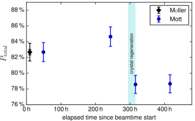
The total beam polarization was measured with a Møller polarimeter (see [12–14] and references therein) at the beginning of the beamtime. The measurements were performed at a beam energy of 855 MeV, be-cause systematic errors related to detector acceptances and signal amplitudes are minimal for this energy. The electron polarization vector was aligned longitudinally (compare Sec. 3) in the spectrometer hall to maximize the sensitivity. The result is P = 82.7% ± 0.3%(stat) ± 1.1%(syst). To monitor the beam polarization through-out the beamtime, we performed several measurements with a Mott polarimeter [15, 16] for transverse horizon-tal alignment of the polarization. The absolute scale of the Mott polarimeter measurements was not calibrated before the experiment, therefore we rescaled the results by a factor 1.018 to match the first Mott polarimeter re-sult with the Møller polarimeter rere-sult. The rere-sults are shown in Fig. 1.
3. Rotation of the polarization vector in the horizon-tal plane
The electron polarization vector precesses on the way through the accelerator to the experimental hall in the fields of the accelerator’s bending magnets. The pre-cession in an electromagnetic field due to Larmor and Thomas precession is described by the Thomas-BMT equation [17]. For the special case of vertical magnetic fields in the recirculating dipoles, only the horizontal components precess with a frequency ω= (1 + aeγ)ωc, where γ is the Lorentz factor and ωcthe cyclotron fre-quency [18]. Due to the anomalous magnetic moment aeof the electron, the polarization precesses faster than the momentum. Therefore the horizontal polarization orientation at the experiment substantially depends on the energy of the extracted beam.
0 h 100 h 200 h 300 h 400 h elapsed time since beamtime start 76 % 78 % 80 % 82 % 84 % 86 % 88 % Ptotal cr ystal regeneration Møller Mott
Figure 1: Measurement of the total beam polarization. The absolute value was measured with the Møller polarimeter. The Mott polarime-ter was used to monitor the usual long-polarime-term increase of the polariza-tion, and the drop of the polarization after a necessary regenerating procedure applied to the source crystal.
The polarization vector can be rotated in the horizon-tal plane by using a Wien filter [18], which is situated in the injection beam line. For conventional polarized experiments, the Wien filter is used to rotate the polar-ization vector so that it is aligned longitudinally in the experimental hall to maximize the sensitivity of experi-mental observables. The rotation angles of the polariza-tion vector through the accelerator have been simulated for standard MAMI energies in [19]. In addition, the rotation angles have been determined for relevant beam energies by measuring the longitudinal beam polariza-tion in the spectrometer hall as a funcpolariza-tion of different rotation angles of the Wien filter. Fitting these results with a cosine function yields the rotation angle of the polarization vector. The achieved accuracy is on the or-der of 2◦. The rotation angles for the beam energies 570 MeV (the beam energy used during the An exper-iment) and 600 MeV (additional Møller measurements were performed at this energy) were determined to be 55◦and 189◦, respectively.
4. Rotation of the polarization vector into the verti-cal direction
The beam polarization vector can be rotated around the beam line axis by applying a solenoidal magnetic field aligned with the beam line axis. Hence, in the ideal case, one can first use the Wien filter to rotate the po-larization vector to a transverse horizontal orientation, then apply a solenoidal field of appropriate strength to rotate it to the vertical direction. We have used a double solenoid which is located shortly behind the Wien fil-ter, see Fig. 2. It consists of two 46 mm long solenoids
Figure 2: Illustration of the steps to align the electron beam polariza-tion vector vertically. The beam is initially emitted with longitudinal polarization. A Wien filter is used to rotate the polarization vector by 90◦in the horizontal plane. Subsequently a solenoidal field rotates the vector into the vertical direction.
(25 mm coils) with an aperture of 30 mm. We have op-erated the two solenoids with the same polarity and with the same current to produce one continuous solenoidal field. The rotation angle of the polarization vector is then proportional to the integral of the longitudinal mag-netic field.
Usually the magnets are operated in such a way that the fields are of opposite orientation and equal in strength, and serve as focusing elements with a focal length of approximately 24 cm inversely proportional to the integral of the squared longitudinal magnetic field. The polarity swap as well as a variation of the solenoid currents changes the focal length. Either the restoration of the original focal length could have been achieved with asymmetric currents in the double solenoid [20], or the effect could have been compensated by tuning of neighboring double solenoids. In practice, none of these methods was necessary. Specifically, during scans of the current in a limited range to optimize the double-solenoid setpoint, the change in focal length was small enough that the phase space of the beam still matched the acceptance of the injector linear accelerator. 4.1. Depolarization effects
Fringe fields and inhomogeneities of the Wien filter and the solenoidal field could, in principle, result in a depolarization of the beam when electrons experience different fields due to the finite phase space volume of the beam.
However, to guarantee the same beam quality for ev-ery beamtime the same optimization procedure is per-formed routinely and results in a well centered beam in every single focusing element. For the small emit-tance of the MAMI beam at these locations of less than 1 π mm mrad and due to the fact that most fringe fields are very similar at the element entrance and exit, the ef-fect is nevertheless negligible and it is not measurable with the MAMI polarimeters.
Depolarization further along the beam line is also negligible: in Refs. [19–21], depolarization effects for
a horizontally polarized beam were evaluated and they were found to be very small. For a vertical beam po-larization alignment, the effects are even smaller due to the small horizontal magnetic field components that the beam experiences. The vertical component is therefore conserved.
In particular, since the depolarization effects are neg-ligible, the vertical polarization component can be de-duced from a determination of the total beam tion “minus” the measured residual horizontal polariza-tion components.
4.2. Consequences of misadjustments of the parameters When the parameters of the Wien filter and the dou-ble solenoid are optimally adjusted, the polarization vector points in the vertical direction directly after the solenoids. Since there are no significant horizontal mag-netic field components and depolarization effects, the beam polarization vector will remain vertically aligned throughout the transfer to the experimental hall with the same polarization degree.
A misadjustment of the parameters however results in significant residual polarization components in the horizontal plane behind the solenoids, thus a reduced vertical beam polarization component. Moreover, the horizontal components can give rise to false asymmetry contributions to experimental observables.
If the rotation angle of the Wien filter is slightly smaller than 90◦, a small longitudinal polarization com-ponent remains. In the solenoidal field, that comcom-ponent is not changed. Due to subsequent polarization vec-tor precession in the acceleravec-tor, that component will be rotated horizontally by+55◦ relative to the momen-tum direction, for the beam energy of the Anexperiment of 570 MeV (compare Sec. 3). For a Wien filter angle slightly larger than 90◦, the corresponding polarization component points in the opposite direction in the exper-imental hall.
In case the field strength of the solenoids is slightly too small or too high to rotate the transverse horizon-tal component into the vertical direction, some polar-ization component remains in the transverse horizontal direction behind the solenoids and ends up in the spec-trometer hall, with an additional relative rotation angle of+55◦again.
Optimization of the Wien filter and double solenoid parameters is performed by considering measurements of the horizontal polarization components as described in detail in the next section.
-7 % -6 % -5 % -4 % -3 % -2 % -1 % 0 % 1 % 2 % 3 % 4 % 5 % 6 % 7 % Pz -7 % -6 % -5 % -4 % -3 % -2 % -1 % 0 % 1 % 2 % 3 % 4 % 5 % 6 % 7 % Px PILAC z PILAC x Pz P600 MeV z
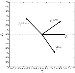
Figure 3: Overview of the polarization components that can be de-termined with the individual polarimeters. The Møller polarimeter is sensitive to Pz. With the Compton (Mott) polarimeter, the longitu-dinal (transverse horizontal) component can be measured behind the ILAC. Due to the precession in the accelerator, this component ends up rotated by+55◦ in the spectrometer hall, the corresponding axis is depicted as PILAC
z (PILACx ). The component along the axis labeled as P600 MeV
z is measured with the Møller polarimeter, when the beam energy is temporarily set to 600 MeV.
5. Vertical alignment procedure
The vertical polarization alignment can accurately be accomplished by minimization of the horizontal polar-ization components. These can be measured at two dif-ferent locations: close to the source with a Compton [22, 23] and a Mott polarimeter and in the experimental hall by using the Møller polarimeter.
The Compton and Mott polarimeters are positioned behind the injector linear accelerator (ILAC), where the 3.5 MeV electrons have already passed the Wien filter and the double solenoid. They are sensitive to the lon-gitudinal and the transverse horizontal components, re-spectively. The Compton polarimeter is therefore well-suited to optimize the rotation angle of the Wien filter. With the Mott polarimeter, the applied field strength of the solenoids can be optimized. Due to the polarization precession in the accelerator, these components are re-lated to the components in the experimental hall by a rotation, see Fig. 3.
Let us denote the transverse horizontal, the vertical, and the longitudinal polarization components in the ex-perimental hall by Px, Py, and Pz, respectively. Pzcan be measured directly with the Møller polarimeter. A possibility for inferring Pxat the experiment is to
tem-0.805 A 0.810 A 0.815 A 0.820 A 0.825 A 0.830 A solenoid current -2.0 % -1.5 % -1.0 % -0.5 % 0.0 % 0.5 % 1.0 % 1.5 % 2.0 % P ILA C x linear fit: P = m· (x − x0) m = (−146 ± 4) %/A x0= (0.8171± 0.0002) A 0.8171 A Mott
Mott, after Wien filter optimization
Figure 4: Measurement of the transverse horizontal polarization com-ponent with the Mott polarimeter in order to optimize the applied solenoid current (circles). Hereafter, a current of 0.817 A for the solenoids was used during optimization of the rotation angle of the Wien filter. With the optimized Wien filter angle, the triangular data points were measured. Only statistical errors are shown.
porarily change the final beam energy so that the rota-tion angle of the polarizarota-tion vector through the acceler-ator is changed accordingly (compare Sec. 3). We used a beam energy of 600 MeV, which is one of the standard energies of MAMI that can be selected by repositioning the beam extraction magnet [24]. In this case the rel-ative rotation angle is ≈ 189◦(see Sec. 3), so the dif-ference to the angle at 570 MeV is approximately 134◦. This polarization component is labeled as P600 MeV
z in
Fig. 3.
For the purpose of the Anexperiment we performed the optimization with Mott and Møller polarimeter mea-surements at the beginning of the experiment and we used the Compton polarimeter for consistency check during the beamtime (Sec. 7).
We first performed the polarization measurements with the Mott polarimeter for different settings of the solenoidal field, with the Wien filter set to the nominal rotation angle of 90◦, see Fig. 4. We chose a current of 0.817 A, for which the magnitude of the transverse horizontal polarization component behind the ILAC was minimal.
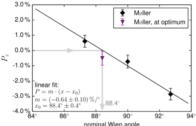
To minimize the second horizontal polarization com-ponent, we performed Møller measurements for di ffer-ent nominal Wien filter angles. The Møller polarime-ter is sensitive to a linear combination of the horizontal components behind the linear accelerator. Given that one of these components has been already minimized by using Mott polarimeter measurements, the second component can be subsequently examined by using the Møller polarimeter. The results are shown in Fig. 5. We found 88.4◦as the optimum value for the nominal rota-tion angle of the Wien filter. With this new Wien filter
84◦ 86◦ 88◦ 90◦ 92◦ 94◦
nominal Wien angle -4.0 % -3.0 % -2.0 % -1.0 % 0.0 % 1.0 % 2.0 % 3.0 % Pz linear fit: P = m· (x − x0) m = (−0.64 ± 0.10) %/◦ x0= 88.4◦± 0.4◦ 88.4 ◦ Møller Møller, at optimum
Figure 5: Measurement of the longitudinal beam polarization compo-nent in the spectrometer hall with the Møller polarimeter (570 MeV beam energy) as a function of the nominal rotation angle of the Wien filter. According to the result of a linear fit on the diamond-shaped data points, a nominal Wien angle of 88.4◦was chosen for the ver-tical polarization measurements. The triangular data point at the fit optimum was gathered directly afterwards. Only statistical errors are shown.
setting, another measurement was performed with the Mott polarimeter (triangular data points in Fig. 4). Due to the good agreement with the previous data points, these settings were used as final values for the beam-normal single-spin asymmetry measurements through-out the beamtime.
6. Systematic errors in the polarimeter measure-ments
The sensitivity of horizontal component measure-ments to a misalignment of the polarization vector is high, at the same time systematic effects can have a sig-nificant influence and deserve special attention.
Uncertainties related to factors entering the polariza-tion determinapolariza-tion like analyzing powers of the reac-tions, absolute target/absorber polarizations, unpolar-ized background, or necessary extrapolations to vanish-ing target thicknesses usually dominate the systematic errors. However, these are negligible when small polar-ization components are measured, because the relative uncertainties of these sources do not change, but the ab-solute uncertainties become small compared to the sta-tistical precision.
In contrast, false asymmetries do not scale with the size of the measured polarization components and be-come dominant when the “true” polarization compo-nents are small. Examples are an inaccurate helicity-dependent luminosity determination used for normal-ization of the raw polarimeter count rates, a slight misalignment of the polarimeter setup, contributions
from another analyzing power component of the scat-tering process utilized for the polarimetry, or a helicity-dependent beam position on the polarimeter target re-sulting in an additional false asymmetry of the count rates.
To get a handle on the systematics, we took data ded-icated to a direct estimate of false asymmetries. Addi-tionally, we compared the data from the different po-larimeters, which have different systematics.
To estimate false asymmetries one needs to perform precise asymmetry measurements of known asymme-tries. One might use for instance an unpolarized beam, an unpolarized absorber (Compton polarimeter), or an unpolarized target (Møller polarimeter).
6.1. False asymmetry estimate of Møller polarimeter measurements
Performing measurements with the Møller polarime-ter with an unpolarized target can be used to estimate false asymmetries, since the expected asymmetry is zero. Depolarizing the standard iron foil might be hard to achieve with the desired accuracy and raises the prob-lem that the target magnetic field is finally turned off, thus slightly changing the trajectories of the electrons. Therefore, we used a copper foil instead. The beam po-larization was oriented vertically during these measure-ments. Since copper is diamagnetic, vanishing asym-metries are expected. The size of false asymasym-metries can then be estimated from the deviation of the mea-surement from zero. Meamea-surements were performed for both relevant beam energies (570 MeV and 600 MeV), and for both λ/2 plate states. The results are shown in Fig. 6. For better comparison, we converted the ob-served asymmetries to apparent polarization values that would be extracted if these asymmetries were measured with the commonly used ferromagnetic target (i.e., we multiplied the observed asymmetries by a factor of ≈ 16, which corresponds to a division by the experimental analyzing power and the effective target electron polar-ization of the iron target). The averaged result of the data for 570 MeV with the λ/2 plate out significantly differs from a zero measurement, which is a clear indi-cation for false asymmetries. Furthermore, it is incom-patible with the result of the data for the same beam energy, but with the λ/2 plate inserted: A two-sample t-test for the null hypothesis that these two data sam-ples originate from the populations with equal means (assuming that they have identical variances) gives a p-value of 0.0013. This strongly indicates that the two population means are not equal. It is more likely that the means are equal in magnitude but have a different sign (p= 0.73). This is an indication that the dominant
part of the false asymmetries is related to beam prop-erties (like helicity-dependent beam positions or aber-rations) rather than to polarimeter issues. However, the deviation from zero is quite small (e.g., 0.42 % abso-lute for the λ/2 plate out data set, which corresponds to an instrumental asymmetry of 0.026 %), and the re-sult for 600 MeV is even compatible with zero. Based on these results, we use the deviations from the zero-asymmetry measurements and their precisions (individ-ually for both λ/2 plate states and beam energies) for a false asymmetry correction and its corresponding sys-tematic error.
6.2. False asymmetry estimate of Mott polarimeter measurements
To estimate false asymmetry contributions to the Mott polarimeter measurements, auxiliary measure-ments have been performed with longitudinally polar-ized electrons at the Mott target. Since the Mott po-larimeter is not sensitive to the longitudinal polarization component, such measurements should result in a van-ishing asymmetry.
Longitudinally polarized electrons are guided di-rectly to the Mott polarimeter when the Wien filter and the solenoids are not used to rotate the polarization. In a strict sense, the polarization orientation is, even in this case, not exactly longitudinal at the Mott target. An α-magnet at the very beginning of the electron beam line bends the 100 keV beam by 270◦ and results in a polarization vector rotation of approximately 0.37◦. Therefore there is a small polarization component in the vertical direction, to which the Mott polarimeter is not sensitive. However, two dipole magnets in the ILAC beam line that are used to bend the beam by 30◦to the Mott polarimeter setup, also cause a slight rotation of the beam polarization in the horizontal plane by 0.27◦ relative to the beam direction. The expected polariza-tion component measurable by the Mott polarimeter is then approximately 0.005 · Ptotal.
We measured a residual polarization of −0.41% ± 0.07% (0.39% ± 0.07%) for the λ/2 plate not inserted (inserted), whereas the expectation due to the dipole bending is 0.39% (−0.39%). We have repeated such measurements in a following beam test, the results were similar. To investigate the source of this deviation, we performed additional systematic tests. After all, the ori-gin of the inconsistency remains unclear. The present estimate for the systematic uncertainty is 0.8% absolute (this value matches the reported deviation). Clarifying this issue thus reducing the magnitude of the total sys-tematic error associated with the polarization measure-ment is beyond the scope of this paper, but thorough
Mean: (0.42± 0.16)% −−−−−−−−−−−−− χ2/dof: 28.13/24 Mean: (−0.35 ± 0.17)% −−−−−−−−−−−−− χ2/dof: 14.50/22 Mean: (0.01± 0.15)% −−−−−−−−−−−−− χ2/dof: 30.00/28 Mean: (0.16± 0.14)% −−−−−−−−−−−−− χ2/dof: 25.35/33 0 20 40 60 80 100 number of measurement -4.0 % -2.0 % 0.0 % 2.0 % 4.0 % extr acted longitudinal polar ization 570MeV data set: (1) 570 MeV (2) 600 MeV (3) 600 MeV (4) λ/2plate out λ/2plate in
Figure 6: Results of Møller measurements on a copper foil. The results are used to estimate the contribution of false asymmetries. Data sets 1 and 2 have been taken at a beam energy of 570 MeV, 3 and 4 at 600 MeV.
measurements will be performed in the near future to understand the deviation.
7. Determination of the polarization orientation In order to reconstruct Pxand Pzand to draw a quan-titative conclusion about the polarization orientation, different types of polarization measurements are per-formed and combined.
7.1. Measurements with optimized settings
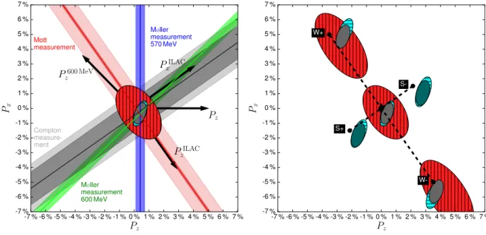
The results for the optimized Wien filter and dou-ble solenoid configurations are depicted in Fig. 7 (left). The Møller polarimeter measurements performed at the beam energy of the An experiment (570 MeV) are sen-sitive to Pz. The measurement result is represented as a line perpendicular to the Pz axis with corresponding error bands. Here, the correction mentioned in Sec. 6.1 has been applied. The results of the Compton and Mott polarimeter measurements as well as the one de-duced from the Møller measurement at a beam energy of 600 MeV are displayed similarly. The inner and outer bands correspond to the statistical and the statistical and systematic errors added in quadrature, respectively. For the Møller measurements, the two bands are hardly dis-tinguishable since the statistical uncertainty is consider-ably larger than the estimated systematic error.
To estimate Pz and Px simultaneously from the dif-ferent polarimeter measurements, we used a maximum-likelihood fit with inputs the measured results and the polarization vector precession angles through the accel-erator. Errors considered in the fitting procedure are the quadratically added statistical and systematic uncertain-ties of the individual measurements. An additional un-certainty enters through the imperfect knowledge of the
polarization vector rotation angles through the acceler-ator. The influence has been checked by varying these angles in the limits of their uncertainties and was found to be negligible.
The result of a fit considering only the Compton and the Mott polarimeter measurements is represented by the vertically hatched ellipse (the 1σ error ellipse cor-responding to the estimated covariance matrix). Fitting the two Møller polarimeter results yields the horizon-tally hatched (blue) ellipse. Despite the different errors, the fit results are very similar. Finally, the result of a fit considering all available polarimeter measurements is shown as the solid ellipse in the figure. The results for Pz, Px, and the covariance matrix C are
(Pz, Px) = (0.39 %, −0.35 %), C = " (0.28 %)2 +(0.24 %)2 +(0.24 %)2 (0.48 %)2 # .
With a total polarization of approximately 79 % at the end of the beamtime, this corresponds to an angle mis-alignment of merely 0.38◦. Therefore, the degree of ver-tical polarization differs only marginally from the total degree of polarization ((Ptotal− Py)/Ptotal= 2 · 10−5). 7.2. Variation of the Wien filter and solenoid settings
We also tested our underlying assumption about how the Wien filter and the solenoidal fields rotate the po-larization orientation. In Fig. 7 (right), the same el-lipses as in the left panel are shown. In addition, the fit results for measurements with changed settings of the Wien filter and the solenoids are drawn. Either the nom-inal Wien filter angle (optimized value: 88.4◦) was var-ied by ±4.3◦, or the current of the solenoids (optimized
-7 % -6 % -5 % -4 % -3 % -2 % -1 % 0 % 1 % 2 % 3 % 4 % 5 % 6 % 7 % Pz -7 % -6 % -5 % -4 % -3 % -2 % -1 % 0 % 1 % 2 % 3 % 4 % 5 % 6 % 7 % Px PILAC z PILAC x Pz P600 MeV z Compton measure-ment Mott measurement Møller measurement 570 MeV Møller measurement 600 MeV -7 % -6 % -5 % -4 % -3 % -2 % -1 % 0 % 1 % 2 % 3 % 4 % 5 % 6 % 7 % Pz -7 % -6 % -5 % -4 % -3 % -2 % -1 % 0 % 1 % 2 % 3 % 4 % 5 % 6 % 7 % Px S-S+ W-W+
Figure 7: Left: Reconstructed horizontal beam polarization components for the optimized Wien filter and solenoid settings. The main component of the polarization points in the y-direction for these settings. The result of a maximum likelihood fit when combining all available polarimeter data is shown as solid ellipse. Consideration of only the Mott and Compton result gives the vertically hatched, combination of the two Møller measurements the horizontally hatched ellipse. Right: Fit results for polarimeter data with slightly changed Wien filter and solenoid settings: The circles with labels S+ (S−) correspond to the expectation when the solenoid current is increased (lowered) by 2 %, as it was done for these measurements. The circles with labels W+ (W−) show the expectations when the rotation angle of the Wien filter is enlarged (reduced) by 5 %.
value: 0.817 A) was changed by ±0.017 A. Comp-ton polarimeter measurements were not performed for the latter settings. The individual results approxi-mately coincide with the expectations (circles labeled by S+, S−, W+, W−).
8. Stability during the beamtime
To check the stability of the polarization alignment on the three-week time scale of the experiment, sev-eral measurements with the Mott polarimeter and the Møller polarimeter at 570 MeV beam energy have been performed throughout the beamtime, see Fig. 8. The agreement between the individual Mott measurements is very good. There is a systematic difference between data collected with and without the λ/2 plate inserted. A small detune of the double solenoid current would cause exactly such an effect. The magnitude of the sys-tematic errors associated with these measurements, as outlined in Sec. 6.2, hampers a verification of such an assumption.
There is a larger spread of data values for the Møller polarimeter measurements. However, these data do not indicate variations of the residual horizontal polariza-tion components above the 1 % level. The
correspond-0 h 100 h 200 h 300 h 400 h
elapsed time since beamtime start -2 % -1 % 0 % 1 % 2 % P ILA C x (Mott) Pz (M øller) cr ystal regeneration
Møller, λ/2 plate out Møller, λ/2 plate in Mott, λ/2 plate out Mott, λ/2 plate in
Figure 8: Measurements of residual polarization components during the beamtime with the Mott polarimeter and the Møller polarimeter at 570 MeV beam energy. Only statistical errors are shown.
ing uncertainties for the analysis of the An experiment are sufficiently small compared to the achieved statisti-cal precision [8].
9. Summary
The Anexperiment of the A1 collaboration was ded-icated to the measurement of the beam-normal single-spin asymmetry in elastic scattering from12C. For this asymmetry measurement, the beam polarization was ro-tated from an initial longitudinal to a vertical orienta-tion. A Wien filter spin rotator (located in the injector linear accelerator beam line) has been used to first ro-tate the polarization into the transverse horizontal plane. Afterwards the polarization was rotated into the vertical direction by means of a solenoidal field of appropriate strength.
In order to measure the total beam polarization, to achieve a good vertical beam polarization alignment and to provide an estimate of remaining horizontal beam po-larization components, numerous polarimeter data have been collected. The absolute beam polarization (around 80 % throughout the beamtime) was determined with a Møller polarimeter by using the most favourable beam energy for that measurement. The variation of the po-larization degree with time was measured with a Mott polarimeter.
To optimize the solenoid current and the Wien fil-ter angle, polarization measurements with the Mott and the Møller polarimeter served as benchmark by pro-viding results for the horizontal polarization compo-nents to be minimized. Dedicated tests have been performed to confirm the expectation for the effect of the Wien filter and solenoid settings on the polariza-tion orientapolariza-tion. To allow a quantitative estimate of residual horizontal polarization components, not only the results from the Mott polarimeter and the Møller polarimeter at the beam energy of the An experiment have been performed, but these were supplemented by Møller polarimeter measurements at a slightly di ffer-ent beam energy and by Compton polarimeter measure-ments. Auxiliary polarimeter measurements have been performed to estimate the contribution of false asym-metries, which are the dominant error sources when measuring small polarization components. Combining these measurements yields horizontal polarization com-ponents, which are indeed close to zero, with uncertain-ties on the 1 %-level. Related uncertainuncertain-ties in the ex-traction of the beam-normal single-spin asymmetry are reasonably small. The newly developed method for de-termining the beam polarization components by using combined measurements of three different polarimeters
will allow future precision studies with polarized beam at MAMI.
Acknowledgement
This work was supported in part by the Deutsche Forschungsgemeinschaft with the Collaborative Re-search Center 1044, the PRISMA (Precision Physics, Fundamental Interactions and Structure of Matter) Clus-ter of Excellence, BMBF Verbundforschung within project 05H12UM6 ”Spin Optimierung”, and the Fed-eral State of Rhineland-Palatinate.
References References
[1] H. Herminghaus, A. Feder, K. H. Kaiser, W. Manz, H. Von Der Schmitt, The Design of a Cascaded 800 MeV Normal Con-ducting CW Racetrack Microtron, Nucl. Instrum. Meth. 138 (1976) 1–12. doi:10.1016/0029-554X(76)90145-2. [2] K. H. Kaiser, et al., The 1.5 GeV harmonic double-sided
mi-crotron at Mainz University, Nucl. Instrum. Meth. A593 (2008) 159–170. doi:10.1016/j.nima.2008.05.018.
[3] M. Dehn, K. Aulenbacher, R. Heine, H. J. Kreidel, U. Ludwig-Mertin, A. Jankowiak, The MAMI C accelerator: The beauty of normal conducting multi-turn recirculators, Eur. Phys. J. ST 198 (2011) 19–47. doi:10.1140/epjst/e2011-01481-4. [4] T. Pospischil, et al., Measurement of GEp/GMpvia polarization
transfer at Q2= 0.4 GeV/c2, Eur. Phys. J. A12 (2001) 125–127. doi:10.1007/s100500170046.
[5] B. S. Schlimme, et al., Measurement of the neutron elec-tric to magnetic form factor ratio at Q2 = 1.58 GeV2 using the reaction3He(~e, e~ 0n)pp, Phys. Rev. Lett. 111 (13) (2013) 132504. arXiv:1307.7361, doi:10.1103/PhysRevLett. 111.132504.
[6] S. Baunack, et al., Measurement of Strange Quark Contributions to the Vector Form Factors of the Proton at Q2= 0.22 (GeV/c)2, Phys. Rev. Lett. 102 (2009) 151803. arXiv:0903.2733, doi: 10.1103/PhysRevLett.102.151803.
[7] S. Abrahamyan, et al., New Measurements of the Transverse Beam Asymmetry for Elastic Electron Scattering from Selected Nuclei, Phys. Rev. Lett. 109 (2012) 192501. arXiv:1208. 6164, doi:10.1103/PhysRevLett.109.192501.
[8] A. Esser, H. Merkel, C. Sfienti, M. Thiel, et al., Measurement of the Beam-Normal Single-Spin Asymmetry for Elastic Scat-tering from Carbon at various Q2, to be published.
[9] K. Aulenbacher, et al., The MAMI source of polarized electrons, Nucl. Instrum. Meth. A391 (1997) 498–506. doi:10.1016/ S0168-9002(97)00528-7.
[10] K. Aulenbacher, Polarized beams for electron accelerators, Eur. Phys. J. ST 198 (2011) 361–380. doi:10.1140/epjst/ e2011-01499-6.
[11] F. E. Maas, et al., Measurement of strange quark contributions to the nucleon’s form-factors at Q2 = 0.230 (GeV/c)2, Phys. Rev. Lett. 93 (2004) 022002. arXiv:nucl-ex/0401019, doi: 10.1103/PhysRevLett.93.022002.
[12] P. Bartsch, Aufbau eines Møller-Polarimeters f¨ur die Drei-Spektrometer-Anlage und Messung der Helizit¨atsasymmetrie in der Reaktion p(e, e0p)π0im Bereich der∆-Resonanz, Ph.D. the-sis, Mainz U., Inst. Kernphys. (2001).
[13] B. S. Schlimme, Messung des elektrischen Neutron-Formfaktors in der Reaktion 3He(~e, e~ 0n)pp bei Q2 = 1.58 (GeV/c)2, Ph.D. thesis, Mainz U., Inst. Kernphys. (2012).
[14] A. Tyukin, Entwicklung, Vorbereitung und Durchf¨uhrung eines Parit¨atsverletzung-Experiments an der A1 Spektrometer An-lage, Master’s thesis, Mainz U., Inst. Kernphys. (2015). [15] V. Tioukine, K. Aulenbacher, E. Riehn, A Mott polarimeter
operating at MeV electron beam energies, Rev. Sci. Instrum. 82 (3). doi:10.1063/1.3556593.
[16] V. Tioukine, K. Aulenbacher, Polarimetry at MAMI, AIP Conf. Proc. 1563 (2013) 276–279. doi:10.1063/1.4829428. [17] V. Bargmann, L. Michel, V. L. Telegdi, Precession of the
po-larization of particles moving in a homogeneous electromag-netic field, Phys. Rev. Lett. 2 (1959) 435–436, [,92(1959)]. doi:10.1103/PhysRevLett.2.435.
[18] V. Tioukine, K. Aulenbacher, Operation of the MAMI accelera-tor with a Wien filter based spin rotation system, Nucl. Instrum. Meth. A568 (2006) 537–542. doi:10.1016/j.nima.2006. 08.022.
[19] M. Steigerwald, Aufbau einer Quelle polarisierter Elektronen am Injektorlinac und Untersuchungen zur Spindynamik im MAMI, Ph.D. thesis, Johannes Gutenberg-Universitt Mainz, Fachbereich Physik (1998).
[20] K. H. Steffens, H. G. Andresen, J. Blume-Werry, F. Klein, K. Aulenbacher, E. Reichert, A Spin rotator for producing a lon-gitudinally polarized electron beam with MAMI, Nucl. Instrum. Meth. A325 (1993) 378–383. doi:10.1016/0168-9002(93) 90383-S.
[21] C. Nachtigall, et al., The new polarized beam injection at MAMI, in: Particle accelerator. Proceedings, 6th European con-ference, EPAC’98, Stockholm, Sweden, June 22-26, 1998. Vol. 1-3, 1998, pp. 1430–1432.
[22] F. Nillius, K. Aulenbacher, Vector polarimetry at MaMi: Measurements of tensor correlation coefficients in e-bremsstrahlungs processes, J. Phys. Conf. Ser. 298 (2011) 012024. doi:10.1088/1742-6596/298/1/012024. [23] F. Nillius, A vector polarimeter at MAMI, PoS PSTP2015
(2016) 031.
[24] M. Dehn, K. Aulenbacher, H. J. Kreidel, F. Nillius, B. S. Schlimme, V. Tioukine, Recent Challenges for the 1.5 GeV MAMI-C Accelerator at JGU Mainz, in: Proceedings, 7th Inter-national Particle Accelerator Conference (IPAC 2016), 2016, p. THPOY026. doi:10.18429/JACoW-IPAC2016-THPOY026.