Laser and Particle Beams (1993), vol. 11, no. 2, pp. 391-414 391 Printed in the United States of America
Heavy-ion accelerators for inertial confinement fusion
By CARLO RUBBIACERN, Geneva, Switzerland
(Received 13 March 1992; accepted 15 May 1992)
Two concepts have been applied to the classical problem of accelerators for the ignition of indirectly driven inertial fusion. The first is the use of non-Liouvillian stacking based on photoionisation of a singly charged ion beam. A special FEL appears the most suited device to generate the appropriate light beam intensity at the required wavelength. The sec-ond is based on the use of a large number of (>1000) beamlets —or "beam straws" —all focussed by an appropriate magnetic structure and concentrated on the same spot on the pellet. The use of a large number of beams —each with a relatively low-current density-elegantly circumvents the problems of space charge, making use of the non-Liouvillian nature of the stopping power of the material of the pellet. The present conceptual design is based on a low-current «/> = 50 mA) heavy-ion beam accelerated with a standard LIN AC structure and accumulated in a stack of rings with the help of photoionisation. Beams are then extracted simultaneously from all the rings and further subdivided with the help of a switchyard of alternate paths separating and synchronising the many bunches from each ring before they hit the pellet. Single beam straws carry a reasonable number of ions: Beams and technology are directly relatable to the ones presently employed, for instance, at the CERN-PS. Space-charge-dominated conditions arise only during the last few turns before extraction and in the beam transport channel to the reaction chamber. In a practical exam-ple, we aim at a peak power of 500 TW delivered to the pellet for a duration of 10-15 ns. High-energy (10 GeV) beam straws of Ba doubly ionised ions are concentrated on several (four) focal spots of a radius of about 1 mm. The power density deposited on these tiny cylindrical absorbers inside a hermetic "hohlraum" is about 2.5 x 10¹⁶ w/g. These condi-tions are believed to be optimal for X-ray conversion, i.e., with an estimated conversion efficiency of about 90%.
1. Introduction
With the exception of thermonuclear explosions, high-power lasers have been so far the almost unique tool for bringing matter to high temperatures and densities. A remarkable amount of work has been carried out in this field that has permitted to highlight an exceed-ingly exciting field of physics rich of applications. Most important, but not the only ones, are the contributions to the energy problem through the possibility of inertially confined fusion. But, one should not forget other possible fields of extraordinary interest. The pos-sibility of compressing matter with extreme pressures paves the way to a number of other subjects. I simply mention here as other possibilities (1) X-ray lasers, (2) fission of micro-chips of compressed plutonium, and (3) extremely strong and confining magnetic fields. As a representative of the particle physics community, I have devoted many years to the realization of ever more ambitious accelerators. I take this opportunity to elaborate on the possible contributions of particle accelerators as drivers to bring matter to such extreme conditions.
The idea to make use of heavy ions to heat matter is an old idea dating back to the mid-1960s. But, the tremendous progress in particle accelerators in recent years, which has per-mitted the realization of beam-beam colliders of extraordinary performances, has important fallouts also in this field. There is today an enormous amount of new developments and expertise in the field of elementary particle physics accelerators that has been accumulated, for instance, at CERN. There is no doubt that this could lead to important fallouts in other domains, including inertial confinement.
Energy transfer between a high-energy beam and matter occurs through the well-known classic ionisation process, originally discussed by Bohr and perfected by Bethe, Fermi, and many others already in the 1930s and 1940s. To enhance the process, the well-known prop-erty on the Z2 dependence of the specific energy loss must be exploited. This is a remark-able property in the sense that, for instance, a 10-GeV bismuth ion can lose all its energy in a material thickness of less than 0.1 g/cm2. As recently shown by the Darmstadt group [Arnold & Meyer-ter-Vehn (1987), for effects of range shortening, see Hofmann et al. (1988)], "hot" absorbers further enhance such a property by a factor that can be as much as two or three.
An accelerated beam of high-energy heavy ions could be used to produce extremely hot filaments that in turn could emit intense radiation in the 200 to 500-eV temperature range. Heating matter with beams, considered as a great inconvenience in particle accelerators, can therefore become an extremely powerful research tool with the help of dedicated machines. The first pioneering step in this field is now possible by the operation of the dedicated accelerator complex SIS/ESR in Darmstadt as discussed at the conference by Rudolph Bock (1993).
Matter at high temperature and density becomes radiation dominated. For instance, the radiation of a 500-eV Stefan-Boltzmann black radiator has a flux of 1016 W/cm and exer-cises an ablative pressure of the order of 108 bars. This radiation in turn becomes a most powerful tool, for instance, to ensure the implosion of small pellets, the so-called indirect drive.
I try to look at the future and delineate a number of conceptual progresses that could further extend the already important possibilities of the SIS/ESR programme, one step closer to the ultimate goals of practical applications, for instance, in the field of energy production.
2. Non-Liouvillian stacking techniques
A far-reaching, novel feature of modern accelerators and storage rings is related to the introduction of methods of circumventing the so-called Liouville theorem. However, most of these methods, like stochastic and electron cooling, do not extrapolate to the needs of the present application for which one deals with lO'VlO16 (singly) ionised heavy ions. Closest to our application is the so-called negative ion injection invented by Budker and now almost universally used in high-energy proton machines. A thin stripping foil is used to convert H~ ions into protons (figure la). The accumulation rate and corresponding phase compression are only limited by the scattering in the foil. This method does not work to stack partially ionised ions, and added selectivity must be introduced to avoid further ionisations after initial accumulation. Because de facto the ionisation is due to "photons"— Fourier transformed from the Coulomb field of the stripper atoms as seen by the moving beam —one could think to extend the concept to heavy ions with the help of a "smart foil" made of an intense and monochromatic beam of UV light (Rubbia 1989) (figure lb). While ionisation from single to double is large, further ionisations of doubly ionised stored ions is either forbidden or strongly suppressed. Typically, single- to double-ionisation
cross-sec-Heavy-ion accelerators for inertia! confinement fusion H "-source am LINAC 393 Stripper foil lon+ lon+
D-LINAC CO o c
FIGURE 1. (a) H injection, following Budker. (b) Injection of heavy ions by photoionisation.
tions for heaviest ions (Bi) are of the order of « 10 n cm. The corresponding light wave-length is in the region of 50-100 nm, below the triple-ionisation threshold. Narrow peaks with an exceedingly large double-ionisation cross-section of resonant nature (about two orders of magnitude larger than the one of the standard outer-shell electrons) have been reported in the case of Ba (figure 2) (Lyon et al. 1988). This enhancement is due to photo-ionisation of inner electrons. Such a large cross-section greatly simplifies the design of the light source,t reducing the requirements of the photon flux to perform the ionisation.
In practice (Rubbia 1989), stacking by photoionisation can be induced along a straight section of the storage ring for the doubly ionised particles, which we assume for simplic-ity to be a matched FODO quadrupole lattice. Injection occurs when the singly ionised beam from the LINAC collides head on with an intense and monochromatic UV light beam. The most appropriate device to produce such a light appears to be a free electron laser (FEL) (Rubbia 1989). Bending magnets at the beginning and end are used to separate the orbit of the singly ionised beam of the LINAC from the equilibrium orbit of the stored beam because magnetic rigidities differ by a factor two. There is a difference in the parameters of the FODO channel between the singly and doubly charged beams and both beams must be separately matched outside the common straight section.
If a parallel optical beam of uniform intensity is matched to the ion beam, the light power needed for an ionisation efficiency r; is
1
"ton "per 2 tan — 1 + sin —
2 \ 2
where eo is the invariant beam emittance, c is the speed of light, e is the elementary charge,
Vy it the photon energy in V, aion is the peak photo ionisation cross-section for Ba, «per is
10'
u
21.10 21.20 21.30 21.10
Photon energy (eV)
21.50 21.60
FIGURE 2. Resonant nature of ionization of singly ionized Ba atoms. Prominent resonances are marked from a to 5 (Rubbia 1989).
the number of complete FODO periods over which collisions occur, and fi+ is the phase advance/period for the singly ionised ions in the channel; n+ is related to the phase advance n++ for the doubly ionised ions from which the structure is tuned:
f l M
/x+ = 2 arcsin - sin ——
For <rion « 2 x 10~15 cm2 = 2 x 10~19 m2, Vy = 22 V, and /x++ = 60°, we find n+ = 28.9°,
namely, n+ ~ fi++/2. Setting for the other parameters /iper = 2, »j = 0.90, and eo = TT X 10~6
mrad, we find Py = 29.28 kW. Note that in the case of nonresonant ions the light
inten-sity required is considerably larger.
In the case of a matched light beam, Py is independent of the length of the periods. In
principle, a large number of periods can be used, with the ultimate limitation due to dif-fraction. Because of the difference in the betatron functions between singly and doubly ion-ised ions, emittance is not conserved through the ionisation process even though the momentum transfer due to the ionisation process is negligible. In practical conditions, a blow-up of some 20-30% has to be accounted for.
In the case of Ba, resonance peaks are narrow (figure 2). This implies that both the pho-ton energy and ion speed must be defined with sufficient precision not to exceed the width of the resonance. While in the case of the FEL this appears as easily attainable and directly related to the stability of the electron energy, special care has to be exercised with the ion beam because the Doppler effect shifts the photon energy in the laboratory A:lab with
respect to the one in the collision frame a kcm by an amount given by AK,
7 ( 1 + 0 ) Ka
= 0 Ap
Heavy-ion accelerators for inertial confinement fusion 395 For T= 5 GeV, y(\ + /3) = 1.281 and AkQm/kcm = 0.213 Ap/p. Peaks 0 and 7 (see figure2) have a width Akcm = 0.025 eV, sufficient to include the Doppler broadening AA:cm = 0.0045
due to a typical momentum spread Ap/p = 10~3.
The requirements on the light source indicate that the FEL must be driven by an elec-tron LINAC. The general applicability of such a device to our case has been discussed (Rub-bia 1989). Subsequently, it has been pointed out by Bonifacio et al. (1990) that the required wavelength, namely, \i o n « 80 nm, can be best produced with a two-stage device in which
light is first amplified at 3Xion followed by a tripler, single-pass stage (figure 3a). This
arrangement in particular permits to use an electron beam (figure 3b) whose properties are less stringent than the ones of a single pass. A fundamental condition for the operation of an FEL is related to the coherence of the source, which in turn can be expressed in terms of the emittance ee,e of the electron beam, the so-called Pellegrini condition, ee|e <
Xphoton-Bonifacio et al. (1990) have shown that with the help of a tripler stage this condition can be somewhat relaxed.
The first stage at 240 nm can be either an amplifier driven by an excimer laser (Bonifa-cio et al. 1990) or alternatively operated as an oscillator (Barbini et al. 1990). There are strong reasons in favour of the latter solution, namely, (1) difficulty of synchronizing an excimer laser and the bunch structure of the LINAC; (2) existence of reasonably efficient mirrors for wavelengths in the region of 240 nm; (3) simplicity of the device because the electron bunch is driving the whole device. A complete design for the laser has been given elsewhere (Barbini et al. 1990), to which we refer for details. Parameters from Barbini et al. (1990) are listed in tables la-lc. One needs a peak bunch (B = 0.1) current of about 200 A at 250 MeV with the invariant emittance of 1.7 x 10~5 rad/m, which is within the state of the art of special photocathodes. Such an FEL will deliver a 1-MW peak after 14.0 m of undulator and will saturate at 69 MW after about 21 m. Because the light power
Single Pass FEL Tripler
Excimer laser
resonance at X = 240 nm (a)
resonance at X = 80 nm
Oscillator FEL Single Pass FEL
e- beam uv-light
resonance at X = 240 nm resonance at X = 80 nm (b)
FIGURE 3. (a) Optical laser-driven scheme for the FEL. A common electron beam traverses undu-lators UM1 and UM2. The third harmonic light generated by UM1 is amplified by UM2. (see Bonifa-cio et al. 1990). (b) Oscillator tripler scheme. A common electron beam traverses undulators UM1 and UM2. Optical cavity UM1 with mirrors lets third harmonic light exit into UM2, where it is am-plified. For details see, tables l a - l c and Barbini et al. (1990).
TABLE 1. Tenative parameters of FEL (a) Electron beam
Energy Peak current E* (inv) zy (inv) °e (b) Oscillator FEL Fundamental wavelength Harmonic wavelength Undulator K Period length Periods number U.N. length X sext. term ysext. term e F(6) Cavity length Gaussian mode waist Laser mode cross-section Cavity losses
Homogeneous gain coefficient Inhomogeneous gain correction Effective gain
Net gain
Allowed peak power Third harmonic power (c) Single-pass FEL Undulator K Period length .Afsext. term Y sext. term Fundamental wavelength F{E)
e-beam transverse size e-beam cross-section P Saturation power Saturation length 1-MW length 215 MeV 200 A 17 mm/mrad 17 mm/mrad 0.2% 240 nm 80 nm 1 4.25 cm 35 1.49 cm 1 1 0.25 0.19 5.07 m 0.24 mm 0.181 mm2 10.20% 53% 0.88 47% 37-27% 1 MW 1 kW 0.7 1.9 cm 1 1 80 nm 0.14 0.22 mm 0.04 mm2 1.6 x 10⁻³ 68.7 MW 21 m 14.33 m Data are from Barbini et al. (1990).
required by photoionisation is considerably smaller, one can reduce correspondingly the fraction of LINAC buckets that are filled. For instance, to produce an "average" power of 69 kW, largely sufficient for the case of Ba, the average LINAC current needs to be about 20 mA. The lasing efficiency of such a device is typically p = 1.5 x 10~3 and an energy recovery for the beam after the undulator is advisable.
Photoionisation stacking has a number of interesting features worth pointing out: (1) It is possible to select only a fraction of the transverse-phase space of the incoming beam with the help of a photon beam of small(er) cross-section; (2) time modulation of the pho-ton beam can be "copied" onto the stored beam; (3) the presence of a sharp variation of the cross-section — like, for instance, in the case of Ba on the falling edge of the resonance—
Heavy-ion accelerators for inertial confinement fusion 397 permits to accumulate selectively particles of a momentum spread narrower than the one of the incoming beam. To fully exploit these features, a multiple traversal scheme of the beam to be stored (rather than single pass) is preferable to avoid the partial utilisation of the incoming particles.
3. The beam straws approach
A second concept that considerably simplifies the design of an accelerator complex for fusion is the use of a large number (> 1000) of beamlets — or beam straws — all focussed by an appropriate magnetic structure and concentrated on the same spot on the pellet. The use of a large number of ordinary beams all converging on the same spot elegantly circum-vents the problems of space charge and exploits the non-Liouvillian nature of the stopping power of the material of the pellet.
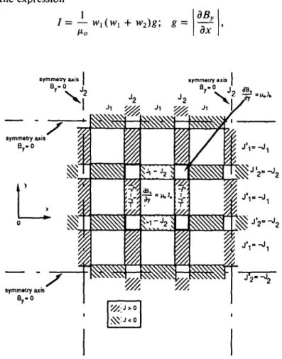
Such a large subdivision permits to maintain the ultimate current on target of each of the beamlets rather low; hence, space charge effects are manageable with small emittances (<10~5 rad/m). Bunches have a number of particles for which a largely proven and reli-able beam manipulation technology exists (CERN-PS). To handle the unprecedented num-ber of beam straws, we need appropriate devices. The key element in the design is the idea of a magnetic focussing lattice, namely, a repetitive (elementary) electrode configuration generating an exact magnetic quadrupole field with a major fraction of the volume free for the passage of beams (figure 4). The current /in the conductors to produce a gradient g is given by the expression
= — wl(w1 Ho w2)g; g = dBy
17
symmetry axis B.-Or
v
symmetry axis symmetry axis B,-0i
I
i
I
symmetry axis \wwII
'/>
where wx is the side of the squared aperture and w2 is the thickness of each of the
conduc-tors (of width w,). The typical gradient g = 20.0 T/m with w, - 5.0 cm, w2= 1.0 cm is
reached with / = 4.77 x 10⁴ A, a reasonable value (the current density is 97.3 A/mm2). The conceptual design of a lattice lens with 256 channels is given in figure 5. Conductors are made of five separately insulated superconducting strands, each carrying about 10 kA. The maximum magnetic field at the conductors is low, i.e., =0.5 T. The gradient required is relatively modest and could be produced as well with the help of permanent magnets. The geometry of the conductors is simple and a large number of beam straws appear prac-ticable in a 2-D matrix-like geometry. However, in contrast to ordinary lenses, the field is determined by the shape and position of currents rather than of the iron yoke, a tech-nique normally used in superconducting accelerators.
To create the large number of beam straws starting from a continuous beam of a stor-age ring, we must split the extracted beams with many bunches into a large number of short beams, each with one bunch before they converge simultaneously onto the pellet. An effi-cient technique is possible in which one can split 2k bunches in k subsequent steps. A
Nitrogen shield Cryostat external vessel
Iron joke (cold) superconducting current elements Return and distribution Helium Separately insulated superconductor strands Detail of current lattice structure
Heavy-ion accelerators for inertia/ confinement fusion 399 "matrix" approach is followed in which the beam from the injector is accumulated (with photoionisation) in a set of N stacked rings, each containing M = 2* bunches. The extrac-tion of the beams from the stacked rings is done in parallel. Bunches of each beam are then divided into two equal half-size strings; the procedure is eventually repeated k times, lead-ing to a total S = N x M beam straws on the pellet. Typically, we assume N = 64 and M = 16, leading to k = 4 and a total of 5 = 1024 beam straws.
Deflectors must be simple, cheap, and reliable because one needs many hundreds of them. Electrostatic deflection seems most appropriate because of the simplicity of construction and because for slow particles it becomes competitive with magnetic deflection. The idea is that of discharging with the help of a thyratron or a spark gap —half-way through the passage of the beam —an initially (and slowly) charged electrostatic deflector. While the first part of the beam is deflected to the longer detour, the latter part continues unperturbed. It may be necessary to modify the relative orientations of a bundle of beam straws, for instance, to focus an initially parallel bundle on the target/pellet or for other operations like separation, merging, and the like. These functions can be achieved by inserting the appropriate current sheets between the straws. If this focussing device is located before the final focus, the subsequent quadrupoles must have a longitudinal geometry tapered in a conical shape to point toward the target. One exploits again the fact that traversing an infi-nite current sheet in the z-x plane of thickness A* with a current density J flowing along the ^-direction there is a change of magnetic induction ABy = /xoJAx. A cellular structure
can be constructed with current sheets of thickness vv2 such that in each beam window of
width w, there is a uniform field of intensity and orientation appropriate to bend the incoming (parallel) straws on a focal point (figure 6). In the overlapping areas, the cur-rent density must be correspondingly doubled. The structure must be biased to have a zero field at the centre with the help of two pairs of external coils with a total current equal to the one in the cellular structure but flowing in the opposite direction. An iron "mirror" is needed as previously to simulate the infinite lattice. Most of the lines of force are making
Arrows indicate B -field directions and
strengths
approximate circles around the centre and the requirements on the mirrors are modest because they absorb mainly "local" field lines.
The current density in the conductors for a device of length L to produce a focal length / is given by the expression
fL
0-3Mo w2 fL
For typical values po/q = 31.4GeV/c,/= 10 m, L = 2 m, w, = 0.05 m, and vv2 = 0.01 m,
we find ABy = 0.314 T and J = 23.14 A/mm2. Like in the case of the quadrupole lattice,
we can use either superconductivity or pulsed conductors. At the edges of the lens, the field is large. For S - 256 and a square geometry, conductors must be arranged in a matrix of
16 x 16 elements and the peak field will be 8 x 0.314 T = 2.51 T.
At the limit of a large number of cells, inner conductors generate an approximately uni-form current density. Within this approximation, the lens has the focussing properties of a "plasma lens" or a "lithium lens," where the linear rise of the field inside a (round) con-ductor is exploited. The cellular structure permits the passage of the particles and ensures that the field within each aperture is constant. There is no "local" focussing on individual beam straws.
In other applications, it may be useful to introduce cylindrical lenses, for instance, to change the relative geometry of straws in one plane. Such lenses can be easily constructed suppressing the relevant half of the conductors. In this case, the iron mirror must convey the return flux from many magnet gaps and must be therefore of larger dimensions.
Along this path, the complexity of the beam transport increases progressively, up to the reaction chamber where beam straws are brought in through a triplet of quadrupole lat-tices and a large number of narrow "windows" converging toward the pellet. An appro-priate field configuration also transforms the geometry of parallel straws into an overall convergence to the focal point —ensuring precise focussing on the same point of the pel-let. In the high-repetition rate case of a practical power station, additional magnetic bend-ing is needed to separate out and absorb with the help of appropriate "beam dumps" the large radiation flux escaping from the combustion chamber through the paths of the beam straws.
4. Space charge limitations
Limitations due to space charge effects are determinant in defining the parameters of the scheme and can be used to define a narrow feasibility window within the delineated gen-eral scenario. Of the many different known types of instabilities that may plague a strong focussing storage and transport system, it turns out that the most relevant to our applica-tion are those associated with the transverse moapplica-tion. Longitudinal effects can be in gen-eral controlled during the short duration of the storage (Hofmann 1984).
One can consider three main critical areas. The first is related to the high current stored in the beams of the storage rings during and particularly at the end of the stacking pro-cess. Limitations of this type occur usually in cyclic accelerators and have been well stud-ied at CERN and elsewhere. The second critical situation occurs at the last phase of bunch compression, just before beams are directed toward the pellet. Because relatively few turns in the rings and the long-beam transport are involved, the instabilities relevant here are the ones occurring in a single pass through a long-beam transport section. There is a consid-erable amount of theoretical work and some experimental work on the subject. However, our understanding of this regime is far less complete than the one in the case of cyclic
accel-Heavy-ion accelerators for inertial confinement fusion 401 erators. Finally, while throughout the beam-transport beam straws can be easily maintained shielded from each other inside the reaction chamber they must converge in "free space." According to a first, qualitative estimate, long-range forces between bunches near the final focus do not seem to be significant, at least as long as the spacing between straws is kept larger than a few beam radii.
All previous considerations apply to beams travelling in high vacuum. In the reaction chamber of a practical energy-generating device operated at high rate, vacuum conditions are necessarily degraded by the previous explosions. The presence of (ionised) residual gas introduces new forces on the beam that must be studied.
The successful ignition of the pellet depends on the properties of the beams converging on it and therefore they are to be set first. Subsequently, the choices for the preceding manipulations should be made in such a way as to meet the requirements of the last com-pression and beam transport.
Let us consider the transverse stability of a single beamlet out of the S beam straws trav-elling toward the target. The maximum current through a beam transport section consist-ing of evenly spaced quadrupoles has been originally considered by Maschke (1976) and Reiser (1978) and further perfected by Hofmann et al. (1983). Experiments have shown that these limits are conservative. If one denotes with fxo the phase advance of betatron
oscil-lation per focussing period in absence of space charge effects, standard theory in absence of the space charge effects ensures stability of particle motion for no < 180°. In the
pres-ence of strong space charge effects, one must require fio < 90° to avoid significant
insta-bilities and even better maintain /io < 60° to avoid a pronounced instability of the
third-order mode. If fourth- and higher-order instabilities must be avoided as well, the con-dition IX/LIO > 0.4 has to be imposed, where /* is the phase advance of betatron oscillation
per focussing period in presence of space charge, i.e. for p > 24° if no = 60°. The
maxi-mum number of ions per unit of length that can then be transported in a FODO channel is proportional to the emittance 7restraw of the beam and is given by (Hofmann et al. 1983):
^%^ = - L 0 V*"
2Q'e
straw; r
o=£rp, (1) where q and A are relative to the ion beam, rp is the classic proton radius, K = ±B'/Bpis the external focussing constant, and Q' = 1 is tabulated in Hofmann et al. (1983). The total number of ions per unit of length incident on the pellet is given by
dN,nl N,c
d/ /3CAT'
where /3c is the ion speed, 7Vtot = E/eT is the total number of ions incident on the filament
during the (uniform) pulse of duration AT, E is the total energy incident on the filament, and e7"it the kinetic energy of the ions. The corresponding quantities for each beam straw are
_ E d7Vstraw 1 E
We make use of expression (1) limiting the current in the transport channel and of the expressions above giving the number of particles to determine the (minimal) emittance of each of the beam straws:
£slraw =
The emittance in turn is related to the spot radius (r) and beam angular divergence <0> in the reactor chamber, estraw = <r><0>. The beam optics inside the reactor chamber is
totally determined by j3* = (r)/(d), the beta function at the collision point, because
with z the longitudinal coordinate (focal point at z — 0). Combining formula (2) with the formula of emittance, we arrive at the following expression giving the space-charge-lim-ited, minimal spot size <r> at the focus (equal to the radius of the radiator):
S03y3cQ'KU2eT AT'
Note that <r> oc 1/Vs", which evidences the non-Liouvillian nature of the energy losses in the absorber and underlines the advantage of keeping the number of straws S as large as possible. The quantity filol = SQstraw = STT(6)2 (where <0> = </->//3*) is particularly
inter-esting because it represents the total solid angle occupied by the straws. Note that fitot oc
1//3* and is independent of 5. Once the nature and kinetic energy of the ions is chosen, space charge conditions and the required value of E/AT determine uniquely the product:
r = a
tot/(33y3cQ'KW2eT AT'
An approximate fit in the interval of 1 GeV < T< 10 GeV with K = 0.267 and Q' = 1 gives the following approximate expressions:
[ E 1
T = 1.181 10~2 — (TW) [r(GeV)]-2-53 Ba
f E 1
T = 1.449 10"2 — (TW) [T"(GeV)]-252 Bi,
with a modest difference between Ba and Bi nuclei. We can, for instance, set the values of fltot and S and derive |3* and <r>:
In the case of N identical focal points, each with S straw beams focussed to the spot, the above relations hold also for the global energy NE on the pellet, the total number of straws NS, and the correspondingly increased solid angle W0lot.
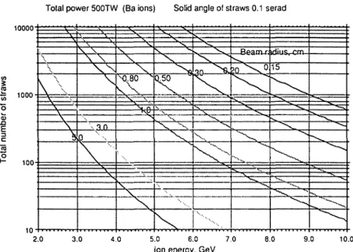
In figure 7, we display the relation between NS and the ion energy for a number of beam focal radii, having set the beam power and duration NE/AT = 500 TW and the total solid angle subtended by the beams as seen from the pellet NUlox = 0.1 sterad. Two
possibili-ties emerge for a reasonable number of straws, NS, of the order of few times 103. In one alternative, the beam spots are focussed down to about 1 to 2-mm radius, corresponding to the "high-energy option" for beams of either Ba or Bi in the 7 to 10-GeV range. At this energy, the range of ions is considerable and a relatively thick absorber is necessary. These are the appropriate conditions for filamentary radiators (Murakami et al. 1990). The sec-ond alternative—more suited for the direct heating of the radiating shell of the hohlraum — corresponds to a focal spot >5-mm radius and is implemented best with low-energy beams with the shortest possible range, i.e., in the region 4-5 GeV. Both alternatives will be briefly reviewed in the next paragraphs.
Heavy-ion accelerators for inertial confinement fusion
Total power 500TW (Ba ions) Solid angle of straws 0.1 serad
403 10000" CO
I
~ 1000-er of
3 C 2 > - 1 0 0 -« - *: . , , . • . • % \W
\
1
—A, X I N ^ \ \ \ \ - ^ \ 3 n \ -^ —^^-— ,:•:. ^ 3L -,....
•\ - V •'••'>\j 30 ^^-^_S^. 1 —Beaow- ^dius—cnv. 15 ^ L__ ^^^^ 1 ^ ^ . . 2.0 3.0 4.0 5.0 6.0 7.0Ion energy, GeV
8.0 9.0 10.0
FIGURE 7. Energy dependence for Ba ions and 500-TW power of the number of beam straws for dif-ferent focal radii as a consequence of space charge limitations in the final focus line.
Within our parameterisation, the value of the betatron function at the focal point /3* is independent of the spot size and is a function only of the main parameters of the scheme — N, S, E/AT, and Qto, — and of the ion kinetic energy and atomic number.
Expe-rience with accelerators and colliders has shown that values of |3* > 5 cm are possible with standard quadrupole focussing and the beam parameters of the kind are presently under consideration. The dependence of the specific energy deposition on the value of /3* is evi-denced in figure 8. One can see that energy depositions well in excess of 1017 W/g are pos-sible in the present scheme.
5. Target issues
Detailed considerations on the physics of the imploding pellet are clearly outside the scope of the article. However, some reference to the underlying phenomenology must be made when seeking an overall optimisation of the main parameters. In the indirect-drive method, intense and highly collimated particle beams are used to produce soft X rays with a bright-ness temperature in excess of 200 eV. These X rays in turn drive the implosion of the pellet that causes the compression and the ignition of the fuel.
To define the radiator configuration and the corresponding parameters for the acceler-ator driver, it is necessary to have a first-order description of the basic physical process of heated matter. The thermal emission from ion-heated matter has been analytically mod-elled in Murakami et al. (1990) starting from numerical simulations. Although approximate, this approach can be effectively used to establish useful criteria for the accelerator design. To ensure the successful implosion of the pellet, the driving forces on the capsule must be extraordinarily uniform because of the emergence of Raleigh-Taylor instabilities. Note that these considerations are independent of the method used to implode the capsule and
io
I10
c en V) c TO 10 16 17 16 1S Nstraws =1024 T 1 • — • s ! — 3 — i otal e -• » -• •""I"-^ « «i
rgy a 5 i = 7.5MJ Nradiators == 4 t""°-i 11 — — { — Ulll k, .01Beta value at target, meters
FIGURE 8. Dependence of the specific energy deposition in cold Al as a function of the value of the /3* at focus for Bi and Ba ion beams.
hold both for laser- and ion-driven implosions and can be associated with a variety of effects, for instance, the finite number of beams on direct-drive ICF, with the hohlraum geometry in X-ray-driven fusion, and with pointing and synchronisation errors.
In a possible geometry, a number of separate filamentary radiators are located symmet-rically inside the hohlraum and are heated by beams accurately aimed at them (Murakami et al. 1990). the radiation heats the cavity, which becomes filled with rather uniform radi-ation density due to multiple radiative exchanges.
The distribution and the number A^rad of such radiators is determined by the necessity
of a uniform illumination of the imploding pellet. The configuration of the hohlraum must meet these margins. A comprehensive discussion of the radiation symmetrisation is given in McCrory and Verdon (1989) and Atzeni (1990, 1991a, 1991b). It appears (Murakami & Nishihara 1986; Caruso 1989; Murakami & Meyer-ter-Vehn 1991a) that a single radiator geometry (Nrad = 1) is excluded, that Nrad = 2 is somewhat marginal, and > 2 radiators
symmetrically located in a spherical cavity configuration are recommended. Therefore, we assume the case of four filamentary radiators (Nrad = 4). The corresponding parameters of the final focus according to the previous space charge considerations are listed in table 2.
TABLE 2. Final focus parameters for Ba ions (Nrad = 4)
Accelerated ions Kinetic energy Total energy deposit Pulse duration Total number of ions Number of radiators Number of straws/radiator Number ions/straw Total solid angle of straws Number of straws/radiator Beta at focus,
Beam emittance, true Beam emittance, inv
Ba++ T E A T Mo, Nni S " s t r a w fito.
s
p*
e £o lOGeV 7.5 MJ 15 ns 4.69 1015 4 256 4.58 1012 0.1 rad 256 0.20 m 4.91 7r ftm/rad 1.59 7r ftm/radHeavy-ion accelerators for inertial confinement fusion 405 The possibility of NTBd > 4 is not outside the resources of the scheme and may be
eventu-ally implemented.
Once the radius of the radiator and the energy and nature of the ions are defined, choice of the longitudinal dimensions /rad of the radiator determines the density of the target
needed to stop the beam. The stopping power for a relatively low-Z absorber (Al) is about twice the one of a heavy target (Au). It has been shown that the range of ions in a highly heated absorber (plasma) is considerably shortened (Arnold & Meyer-ter-Vehn 1987), the effect amounting to a factor two already for a few eV temperature. However, the radiator is quickly disintegrated by the beam and the density may be considerably reduced during the heating process. A beam stopper is therefore necessary at the end of the radiator to avoid the early fraction of the beam hitting the pellet: such an additional heating may indeed be harmful to the symmetry of the driving forces.
The heating process of a single cylindrical absorber hit by a number of beam straws can be studied making use of the model described in Murakami et al. (1990), which is in good agreement with the radiation hydrodynamic code MULTI (Ramis et al. 1988). We consid-ered three different target materials: low Z (plastic), medium Z (Al), and high Z (Au). Again, a number of parameters are assigned and calculations are performed taking the beam energy as a variable: Afrad = 4, N^E/AT = 500 TW, 7VradS = 1024, Qtot = 0.1 sterad, and
/rad = 4 mm. The relevant parameter, plotted in figure 9 is the conversion efficiency of the
incoming beam into radiation. The radius of the target is set equal to the radius of the beam and the target density is adjusted to the range for cold matter. The radiation efficiency is small at low energies because of the considerable radial dimensions of the target. Energies in excess of 8 GeV are necessary for an efficient conversion and Au is significantly less effi-cient than medium- and low-Z targets. This is due to the smaller stopping power and the higher opacity, which implies a larger core temperature for a given surface temperature. Parameters for 10 GeV are listed in table 3a for Ba and table 3b for Bi. Due to the beam losses, the target is heated rapidly (heating time) to a regime temperature in excess of 200 eV. Because of the target opacity, the centre of the rod is considerably hotter. This effect is particularly striking for a high-Z target. From the accelerator point of view, there is lit-tle or no difference in using either Ba or Bi nuclei because the radiative process at these power densities is efficient (Murakami et al. 1990).
1.00 0.90 0.80 5" 0.70 M 0.60 ~V 2 0-50 CO
1
0M I" 0.30 X 0.20 0.10 0.00 i i i//
//
//f/\
7/
! A
i ; 1 i WasTii
3.0 4.0 5.0 6.0 7.0Ion kinetic Energy, GeV
8.0 9.0 10.0
FIGURE 9. Efficiency in energy transfer to X rays as a function of the ion beam energy for Ba ions. For details, see text.
TABLE 3 Performance of filamentary radiators for ions according to the approximate model of Murakami et al. (1990)
Target Ba Range (g/cm2) Density (g/cm3) Mass (mg) Power density x 10~16 (W/g) Temp. surf. (eV)
Temp, centre (eV) Heating time (ns) Rad. time (ns) Rad. efficiency Bi Range (g/cm2) Density (g/cm3) Mass (mg) Power density x 10~16 (W/g) Temp. surf. (eV)
Temp, centre (eV) Heating time (ns) Rad. time (ns) Rad. efficiency Plastic 0.14 0.35 5.53 2.26 223.45 319.67 1.79 13.21 0.87 0.05 0.13 2.56 4.88 450.08 458.15 1.28 13.72 0.91 Al 0.14 0.35 5.53 2.26 216.59 310.66 1.56 13.44 0.89 0.05 0.13 2.56 4.88 211.99 256.96 0.57 14.43 0.96 Au 0.26 0.64 10.10 1.24 215.95 547.55 4.28 10.72 0.74 0.10 0.26 5.15 2.43 210.74 459.63 1.65 13.35 0.90
The typical radiation flux inside the cavity due to the filamentary radiators is of order Sa = 1014 W/cm2 and is absorbed by a thin surface layer of the hohlraum shell and
trans-ported deeper into the material by diffusion. The depth of such a strongly heated layer has been approximately parameterised in Murakami and Meyer-ter-Vehn (1991b). The amount of material ablated is exemplified for a solid-gold shell and typical conditions of 500-TW pulse and a 5-mm radius spherical hohlraum. One finds that both the amount of heated material (130 mg after 10 ns) and the depth of ablation (41.5 mg/cm2) are considerable. It should be, however, noted that the primary requirement of the hohlraum is of being opti-cally thick and this can be already achieved with smaller thickness because the optical absorption length at 300 eV for solid gold is about 2.0 mg/cm2. The total ablation of the shell is acceptable at the price of some radiation leakage as long as it remains optically thick (<20 mg/cm2).
It may be worthwhile exploring whether alternative configurations within the previous considerations on space charge limitations of the accelerator complex may also be capa-ble of producing the required effective conversion of the beam energy into an intense burst of soft X rays. If the kinetic energy of the ion beams is reduced to a few GeV, the range of the particles becomes comparable to the thickness of the radiation-ablated shell. Fur-ther—due to space charge effects—the beam cross-section at the focal point must be con-siderably increased and becomes comparable to the outer size of the shell. In these conditions, the approach of a number of "hot filaments" can no longer be used and it is preferable to choose the alternative configuration in which the beam heats the wall of the cavity directly, bypassing the intermediate phase of the filamentary radiators. To ensure uniform heating, the shell must be illuminated by a relatively large number of independent beams, a necessity in the case of low-energy drivers. This scheme differs from direct drive because additional uniformisation is introduced by the reemission and absorption of the radiation inside the hohlraum.
Heavy-ion accelerators for inertial confinement fusion 407 The parameters of the beams are evidently different. As already pointed out, the primary requirement of the hohlraum is to be optically thick, and this can be achieved at least with high-Z materials with smaller thickness because the optical absorption length at 300 eV for solid gold is about 2.0 mg/cm2. The beam range needs to be not larger than the thickness of material ablated by the X rays (typically 40 mg/cm2 after 15 ns) or eventually thinner because total ablation of the shell may be acceptable as long as it remains optically thick (<20 mg/cm2). Ranges on the region of 20-40 mg/cm2 correspond for (hot) heavy-Z mate-rials to kinetic ion energies in the region of a few GeV. Fortunately, the beam radius must be considerably larger to invest the whole hohlraum (>5 mm). The beam emittance and the number of straws required by the space charge limitations for 500-TW peak power deliv-ered onto a pellet of 5-mm radius within a total subtended solid angle of the reaction cham-ber covered by beams of Qtot = 0.1 sterad can be deduced from the previous analysis.
These parameters can be satisfied with a reasonable number of straws, S = 2048, and an acceptable emittance e = 20 TT X 10~6 rad/m for T= 5 GeV and Bi. In the case of Ba ions, the option S = 2048 corresponds to slightly different parameters, T= 4.55 GeV and e = 19.5 IT X 10~6 rad/m. The number of straws S is an extremely steep function of energy and varies as l/fitot. Ranges are, of course, different depending on the types of ions.
Taking gold for the cavity and carbon for the capsule ablator, under optimum condi-tions the implosion velocity of >3 X 107 cm/s is reached with temperature of the cavity walls of about 250 eV. A first order of magnitude estimate can be set by the internal energy needed to reach such a temperature, E-m. The internal energy Eint is an appropriate
inte-gral over the temperature converter of Me(T), where e(T), the specific internal energy, is parameterised as e(T) = egT11. These power law expressions are crude approximations of the actual equation of state. Inserting these definitions, for a heating time th the
depo-sition power per unit of mass is
e(T ) e T?
p _ <-\' is) _ co* is
th th
Taking e(T) = 2.2 x 10³ T1 6 (eV) (J/g), which is given in Murakami et al. (1990) for gold, T = 250 eV, th = 3 ns, we find P = 5 x 10¹⁵ W/g, which gives the order of magnitude of P to be provided by the beams.
After the converter has heated to its working temperature at the inner wall, additional energy must be provided by the beams to compensate both for radiation and hydrodynamic expansions. In the present conditions of optically thick absorber (TC » 1), the temperature
is not uniform and the inner temperature Tis is higher than the one at the surface 7OS. This
is due to a diffusive transport toward the surface, where the energy is radiated away. Fol-lowing the case of the plane photosphere (Murakami et al. 1990), the temperature profile has the form
T/ _ \ T- /1 i 3_\l/4 / (r) = los(l + 2T> >
where the optical thickness T is running from the outer surface inward. The radiation flux to the outside of the hohlraum is Sou, = 2oToS, where the factor 2 takes into account the
fact that photons are originated on the average somewhat deeper than the surface. Results are as follows: (1) After 11.4 ns, the outer temperature is 200 eV while the interior of the hohlraum is at 482 eV; (2) at the end of the pulse, after 15.0 ns the outer temperature has risen to 250 eV while the hohlraum is at 577 eV. It would seem that this method is capable of higher temperatures. There is no equilibrium situation, and the pressure at the pellet rises with time. The effects on implosion must be investigated and in general it must be stressed at this stage that more work is clearly necessary before fully assessing the potentialities of a diffused radiator geometry.
6. Practical scheme
Now that the parameters of the final focus have been narrowed down, we can consider the requirements on the storage rings that supply the ions (table 4). We neglect at this stage phase space blow-up and particle losses in these manipulations, which consist simply of a longitudinal bunch compression followed by extraction and transfers. No bunch coales-cence is used and therefore both the number of bunches and the total number of particles/ bunch are conserved.
The total number of rings nTmgs is related to the number of bunches h that can be stored in each ring because S = hnTings. The number of straws S, the beam transverse emittance e, and the number of ions in each straw Nstraw are largely determined by the required
prop-erties of the final focus and the space charge limitations in the final transport section and are considered at this point as fixed. The total number of ions that can be stored in each ring and hence the number of straws (bunches) that can be constructed from each ring is determined by the stability limit in the transverse plane due to the maximum incoherent tune shift (Laslett) at the much more "relaxed" bunching during storage and stacking:
1 B . „ _q^ r0 h
where B is the bunching factor and AQ the largest allowed tune shift. One can relate this condition to the one of the final focus following equation (1), which can be rewritten as
TABLE 4. Tentative parameters of the storage rings Type of lattice
Kinetic energy for B a+ + Momentum po/q
Bending field atp0, Bo
Magnetic curvature radius, r Number of periods
Phase advance, ^ Tune
Periods with bending Length of period, L
Length of magnets (magnetic) Length of lenses (magnetic) Empty cells
Quadrupole gradient Beta functions
max, 6max min, bmin
Nominal beam emittance, s Beam radius m a x , ^ a x min, rmin Circumference Number of bunches Bunching factor, B
Total number of particles for AQ < 0.5 Particles/bunch
Average stored current </> Revolution time for B a+ + Time distance between bunches
FODO lOGeV 31.4GeV/c 1.8 T 47.23 m 40 60° =6.6 32 12.5 m 4.46 m 0.90 m 8(4 x 2) 20.0 T/m 21.38 m 7.28 m 4.91 7T urn 1.02 cm 0.60 cm 500 m 16 TT/4 7.57 1013 4.73 1012 5.55 A 4.36 us 272 ns
Heavy-ion accelerators for inertial confinement fusion 409
N — — R2-v3K1/2n'F /
1 'straw — . P I *» <t£ '•straw'straw >
"To
where /straw is the effective length of the beam straw at the pellet. Combining the two
equa-tions, we find a simple expression giving the total straw length at the final focus that each ring can supply:
16TTB AQ
'straw" - ~~j£T7T
~~X7-Note the purely "geometric" nature of the expression above, which is independent of the nature, energy, and transverse emittance of the ion beam. This is due to the fact that both limitations have a common physical origin.
Setting as values K = 0.25 m~2, Q' = 1, B = 1/2, and AQ = 0.5, the largest value for the PS booster, we find /straw/i = 25.12 m (note that /straw = /3CAT and for the typical
val-ues (3 = 0.3, AT = 10~8, giving /straw = 0.9 m). These general considerations suggest that
if ft has to be the largest possible number of the form 2* with k integer then h = 16 and therefore nrings = S/h = S/16. Hence, the number of beams splitting that are optimal to the scheme is rather rigidly determined by space charge considerations.
The general layout of the accelerator complex is shown in figure 10. Parameters given in table 5 are for four filamentary radiators heated by Ba beams at 10 GeV. The duration of the storage of the beam in the rings is limited to few tens of milliseconds because of the presence of inelastic charge exchange intrabeam collisions, which lead to a significant loss rate of the stored ions. In practice, the storage time is close to the accumulation time dur-ing which the current is risdur-ing linearly in all rdur-ings as a function of time to the peak value, which is of the order of a few amperes.
The most conservative and safest way to accelerate the ion beam from the source to the final energy is a classical LINAC. The current of singly ionised ions from a LINAC can be typically of the order of 50-100 mA with an invariant emittance of about 1.0 x 10~6 irrad/m. Other techniques like a recirculating (induction) accelerator are possible but require a significant amount of development although they may eventually lead to some cost sav-ings. For an average current </>, the filling time is given by
TABLE 5. Main parameters of the FODO final beam transport channels Type of lattice
Nominal momentum po/q Length of period, L Free length between lenses Length of lenses (magnetic) Quadrupole gradient
Phase advance, no space charge, no Phase advance, full space charge, n Beta functions @ n = 60° (no space charge)
max, |3max
min, /3min
Beta functions @ \i = 24° (full space charge)
m a x , j3m a x
m i n , j3m i n
Admittance, true, aslraw
Radial aperture (j3 = /3m a x; n = 24°, « = e) FODO 31.4GeV/c 12.5 m 4.46 m 0.90 m 20.00 T/m 60° 24° 21.38 m 7.28 m 32.13 m 20.80 m 20.00ir* fim/rad 24.90 mm
I—•— • 0 3 2 turn s Heli x (up ) Ejec t 50 0 meter s 100 0 phot o -ionizatio n injectio n s.s . Kicke r Kicke r 3 2 turn s Heli x (down ) FIGUR E 10 . Genera l layout . Kicke r 150 0
Heavy-ion accelerators for inert ial confinement fusion 411 E
'nn —
where E is the total delivered energy, T is the ion kinetic energy in eV, and 77 is the stack-ing efficiency. Settstack-ing E = 7.5 MJ, T= 1010 V, 77 = 0.9, and </> = 50 mA, we find trM = 16.6 ms.
The beam from the LINAC is stacked in a relatively large number of storage rings. The optics of each ring is taken to be a simple FODO lattice with bending magnets inserted between quadrupoles. There are constraints on the lattice coming from the necessity of transporting high currents during the last phase of accumulation. The optics of these rings cannot be excessively sophisticated because the defocussing effects of the space charges introduced large detuning effects and major changes of the betatron functions during the stacking. Fortunately, the momentum spread is relatively small and chromatic corrections can be neglected to a greater extent. The beam circulates for a short time and resonance effects should not have time to develop. Hence, higher-order corrections may also be neglected. This is an important point that must be verified by more extensive computer sim-ulations.
For simplicity and to avoid matching problems in the presence of massive space charge effects, we assume that the whole complex from the injection in the ring to the final focus onto the pellet is a repetition of the same FODO lattice with the space between quadru-poles used for bending magnets, RF cavities, kickers, etc. A critical parameter in the pres-ence of high space charge effects (Hofmann et al. 1983) is filling factor <p, namely, the fraction of the lattice occupied by focussing elements. The highest stability is reached with continuous focussing (<p — 1) because it has been shown that even in the presence of strong space charge forces a large class of solutions are stable (Kapichinskij & Vladimirskij 1959; Davison & Krall 1970; Gluckstern et al. 1970). For a typical value <p = 1/5, the "figure of merit" that measures the maximum transportable beam current or power for a given emit-tance and quadrupole pole tip field is lower than the ideal case <p = 1 by approximately a factor of 2 (Hofmann et al. 1983).
Each ring is made of a FODO lattice with <p = 1/5 and bending magnets inserted between equally spaced quadrupole lenses. Two periods in each of the four equally spaced super-periods are left empty for extraction, RF, etc. To maintain compatibility with the beam transport to the targets, the phase advance is n — 60°.
As already pointed out, there is need for a large number of such rings to be filled in series from the LINAC and emptied in parallel toward the reaction chamber. The most reason-able geometry, following the example of the PS booster, is the one of a series of stacked rings, sharing the main elements of the magnetic structure. Because the number of rings is larger, the structure needs to be more compact and many rings could be stacked vertically. Injection from the LINAC must be performed for a large number of rings. A set of sep-arate injections for each ring will be complicated and costly. In order to perform it in a continuous way, it is proposed to adopt a scheme in which the trajectory of particles through two stacks of rings is organized as a double helix (figure 11). Of course, while recircula-tion of the beam during storage occurs through all the rings, beam extracrecircula-tion is performed from all rings simultaneously.
In practice, we propose to arrange the elements of the ring stack in a progressively ris-ing succession in such a way that in a full turn the beam has risen exactly by one unit of spacing between rings, leading to an open helical trajectory with ends at the top and bot-tom of the stack. Two such counterrotating helixes are then interconnected by two long, straight sections —one at the top and other at the bottom —continuing the standard FODO structure. In one of such straight sections, injection by photoionisation is performed, with
Descending Helical Ring structure M/2 turns Ascending Helical Ring structure M/2 turns
Singly Ionized Ions from Injector
Beam Dump for LINAC beam Photo-ionization
Injection Ion* => I o n "
Photo beam from FEL ionizer
FIGURE 11. Stacked ring geometry and possible photoionisation arrangement. The rings are filled in series and transferred to the target in parallel.
the singly ionized beam travelling through the same quadrupoles as the stored beam and bending magnets separating the trajectories at the ends. This method appears feasible, although it requires an additional effort in reducing the alignment errors with respect to the case of separate rings (Mohl 1991). If further investigations were to show that this is not acceptable, one can always revert to the classic geometry of many rings and indepen-dent injection. Then, an intermediate ring is used to accumulate ions and one-turn trans-fer is used to fill rings in succession.
RF cavities are located in the long, straight sections and are shared among all (or at least a group of) the rings of the stack. The RF is used to maintain the beam bunched during the stacking process with a relatively low bunching factor to be able to accumulate the larg-est possible number of ions around the circumference. Shortly before extraction, the RF voltage is increased and appropriate RF manipulations permit compressing the bunches to the required length. This process must occur quickly enough not to cause beam losses due to crossing of betatron resonances. Extraction from all the rings is then performed simul-taneously as a one-turn extraction in one or several channels and requires a full aperture set of kickers with rise time faster than the bunch spacing.
The parameters of the beam transport are listed in table 5 and the geometry of the split-ting procedure for the bunch trains is shown in figure 11. Separation of the beams is pro-vided by a deflector, which performs a transition halfway during the passage of the beam to splice the bunch train. The two alternate paths are arranged in such a way as to bring into identical timing the two halves of the bunch train. With this technique, one can sepa-rate out and synchronize 2k bunches in k subsequent steps. Our numerical example assumes M- 64 and therefore k = 5. The difference between the two paths, initially equal to half the circumference of the storage rings, is progressively reduced as powers of two at each step.
The final focus onto the pellet is the densest part of the beam straw geometry. The gen-eral layout is reminiscent of the low-/? crossing in a high-energy collider. There is large lat-itude in the choice of the focal strength at the focus and the relatively modest momentum spread of the beams (Ap/p ~ 1-2 x 10~3) allows a modest effort in chromatic corrections.
Heavy-ion accelerators for inertial confinement fusion 413 The range of ions in the absorber is short («: a few millimetres), there is in general little or no "focal depth" effect, and full convergence on the pellet could be ensured even from large angles. However —as already pointed out —the beam optics inside the reactor cham-ber is totally determined by j3* = <r>/<0>, the beta function at the collision point. A smaller value of j8* for a fixed focal radius will also imply a larger beam at the edge of the chamber, which in turn increases the dimensions of the beam access portholes. In practice, the fraction of the solid angle covered by the windows is about two to three times fitot and
the amount of radiant energy escaping the chamber is not negligible. It is therefore impor-tant that both the heat and the radiation are contained. This can be achieved with the help of an s-shaped magnetic deflection and appropriate beam dumps. Even 1% of the total energy may amount to as much as 10-20 MW for a large-scale power station.
In view of these problems, the use of superconducting magnets may be difficult and the possibility of using either pulsed lenses or permanent magnets should be examined.
7. Summary of conclusions
There are a number of novel techniques developed in HEP that may be beneficial to heavy-ion-induced confinement applications. Non-Liouvillian stacking appears feasible for Bi (HIBALL) and favourable for Ba. It requires the practical development of an FEL now only on paper. A bold extension of the multiple-ring technique of the PS booster to ion stacking and = 1000 beam straws would permit to design rings with individual beams in the domain of operation, which has been well tested experimentally, e.g., at CERN. Existing and proven techniques allow to reach parameters that meet likely conditions for indirectly driven ignition, e.g., E = 5-10 MJ, r = 10-15 ns, W > 1016 W/g. For the filamentary approach of Murakami and Meyer-ter-Vehn, it is possible to achieve adequate energy depo-sitions with four radiators and Ba ions with kinetic energies of 8-10 GeV in a compact ring configuration fed by a standard LINAC (50 mA). A promising alternative that, however, needs further study is the direct heating of the walls of the hohlraum with low-energy (=5 GeV) ion beams. It would appear that a more efficient and hotter capsule can be made with an even smaller accelerator configuration.
Although the dedicated accelerator complex SIS/ESR in Darmstadt has only just started operation, time has come to start preparing for the next step.
Acknowledgments
The author extends the warmest thanks to the many people who contributed to the devel-opments of the concepts contained in the present article. In particular, he mentions Stefano Atzeni, Albert Hofmann, Ingo Hofmann, Kurt Hiibner, Dieter Mohl, Mario Puglisi, Peter Sievers, Albin Wrulich, Bruno Zotter, and J. Meyer-ter-Vehn.
REFERENCES
ARNOLD, R.C. & MEYER-TER-VEHN, J. (1987) Rep. Progr. Phys. 50, 559.
ATZENI, S. \990 Europhys. Lett. 11, 639.
ATZENI, S. 1991a Laser and Particle Beams 9, 233-245. ATZENI, S. 1991b Particle Accel, (in press).
BARBINI, R. et al. 1990 ENEA Report RT/INN/90/35, ENEA, Frascati. BOCK, R. 1993 Laser and Particle Beams 11, (in press).
BONIFACIO, R. et al. 1990 Sezione di Milano preprint (unpublished).
CARUSO, A. 1989 In Inertial Confinement Fusion, A. Caruso and E. Sindoni, eds. (Compositori-SIF, Bologna), p. 139.
DAVISON, R.C. & KRALL, N.A. 1970 Phys. Fluids 13, 1543.
GLUCKSTERN, R.L. etal. Proceedings of the 1970 National Accelerator Lab. Linear Accelerator Conf. (FNAL), Vol. 2, p. 823.
HOFMANN, D.H.H. et al. 1988 Z. Phys. A 330, 339. HOFMANN, I. et al. 1983 Particle Accel. 13, 145.
HOFMANN, 1. 1984 In Proceedings of the 1984 INS-International Symposium on Heavy Ion
Acceler-ators and Their Application to Inertial Fusion, p. 238.
KAPICHINSKIJ, l.M. & VLADIMIRSKIJ, V.V. 1959 In Proceedings of the 1959 International Conference
on High Energy Accelerators, (CERN), p. 274.
LYON, L. et al. 1988 J. Phys. B. Atom. Mol. Phys. 196, 4737.
MASCHKE, A.W. 1976 unpublished.
MCCRORY, R.L. & VERDON, C.P. 1989 In Inertial Confinement Fusion, A. Caruso and E. Sindoni, eds. (Compositori-SIF, Bologna), p. 183.
MOHL, D. 1991 Transverse space-charge effects in heavy ion storage ring(s) for inertial confinement fusion, preliminary draft (CERN, Geneva).
MURAKAMI, M. & MEYER-TER-VEHN, J. 1991a Nucl. Fusion (in press).
MURAKAMI, M. & MEYER-TER-VEHN, J. 1991b Max-Planck-Institute fur QuantenOptik preprint.
MURAKAMI, M. & NISHIHARA, K. 1986 Jpn. J. Appl. Phys. 25, 242.
MURAKAMI, M. et al. 1990 J. X-Ray Sci. Tech. 2, 127. RAMIS, R. et al. 1988 Comp. Phys. Comm. 49, 475. REISER, M. 1978 Particle Accel. 8, 167.