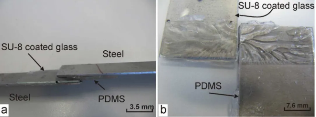
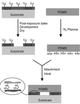
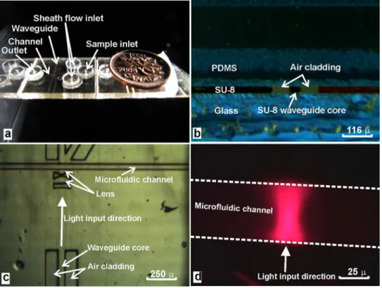
Sealing SU-8 microfluidic channels using PDMS
Texte intégral
Figure


Documents relatifs
Consequently, we decided to add TEMPO in order to make the PDMS crosslinking kinetics compatible with the melting temperature of PA12 (T=180°C) and with the
Whereas the reaction between tBAP and silane monomers BP3DM2Si occured in good yields, and further polymerization led to peroxide grafted silicone polymers, grafting of the
Chapter II will investigate the grafting of well-defined boron-containing compounds on silica surfaces in order to provide a molecular understanding of the
Its protection ability against impuri- ties could also be proven by the successful analysis of numerous serum samples (some hundred) during the course of
From these studies, we conclude that the presence of ordered clusters in the sample matrix for the test molecule used in this study, has a marked influence on the
Figure 3 shows the measured electrical
Therefore, the analyzed period of 1965–1991 of increas- ing geomagnetic activity should result in negative NmF2 and positive hmF2 trends, as our previous analysis has shown
28 Letzten Endes stellt sich die Frage, wie man sich zum Stocken des Gedichts in der Rezeption – und also auch auf der Ebene der Wissenschaft, der Sekundärliteratur – verhalten
